GreenMirror: A Visualization and Animation Framework
for State-Transition Models
Bachelor assignment
K.M. El Assal (s1097539)
University of Twente
P.O. Box 217, 7500AE Enschede, the Netherlands
[email protected]
Exam committee:
prof.dr.ir. A. Rensink
dr. H.K. Hemmes
repository:
https://github.com/iisys-/GreenMirror
August 13, 2015
Abstract
Contents
1 Introduction 4
1.1 Background . . . 4
1.2 Glossary . . . 4
1.3 Stakeholders. . . 5
1.4 Project denition . . . 6
2 The ferryman 9 3 Features 13 3.1 Client and server . . . 13
3.2 Nodes and relations . . . 13
3.3 Node placement. . . 14
3.4 Commands . . . 15
3.5 Log. . . 17
3.6 The GridBuilder class. . . 18
4 Design and implementation 19 4.1 Package structure. . . 19
4.2 General work-ow . . . 20
4.3 Detailed work-ow . . . 20
4.4 Interface design . . . 22
4.5 Implemented design patterns . . . 24
4.6 Internal representation of visual node properties . . . 27
4.7 Internal representation of states and state-transitions. . . 27
4.8 Interchange formats . . . 28
5 Validation 29 6 Discussion 33 A Service extension instructions 35 A.1 ModelInitializer . . . 35
A.2 TraceSelector . . . 35
A.4 FxPropertyWrapper . . . 35
A.5 Placement. . . 36
A.6 Command . . . 36
A.7 CommandHandler . . . 36
A.8 CommandLineOptionHandler . . . 36
A.9 Log. . . 37
1 Introduction
This report describes the GreenMirror framework: a tool for visualizing and animating state-transition models. The current section contains background information needed to understand this project and the rest of the report. Section2gives an example of the usage of the GreenMirror application. The example model is the ferryman puzzle and shows how one can switch from a state space generation tool to the GreenMirror tool. The features of the application and their usage are described in section3, which is particularly useful for the end-users of GreenMirror. Section4follows with a description about how the design and implementation of the GreenMirror framework look like and is useful for future developers and also in part for tool owners. Validation of the system is described in section 5 and this report concludes with section6 discussing the developed system and providing suggestions for future improvements. This report has been written for anyone who wants to use the GreenMirror tool, which is why the current structure has been chosen: rst can be seen why the system has been developed, then what the possibilities of the system are and nally how the system is developed and how the project was dened.
1.1 Background
State-transition models describe the discrete dynamic behaviour of a system or process. Such a model denes how the state of a system changes as the result of a trigger, and following its set of model rules. In the eld of computer science, these models are used for system verication and analysis. Verication and analysis are done, for example, to conrm and prove a process can not enter a deadlock state. One way of analysing a state-transition model is by analysing its state space, which a state space generation tool such as GROOVE [10] can generate.
State spaces can become huge, complex and dicult to analyse. The research group Formal Methods and Tools1 of the University of Twente has set out to develop a framework based on
the Java programming language and the JavaFX library that enables researchers to analyse state-transition models using a dierent approach. The idea is to visualize the system state and animate the state-transitions of a user-specied state-transition model with the goal of gaining a better understanding of the model and its aws.
The rst step in the development of this framework has been made by Alex Aalbertsberg [1]. This report describes how his framework has been redesigned and how it has implemented more extensive features. The current version has been named GreenMirror. Although the project is far from complete, hopefully these contributions will eventually lead to better state-transition model research.
1.2 Glossary
Some terms in this report can be ambiguous or unclear in their meaning. For that reason, the following glossary is provided which will make their meaning denitive.
The application This refers to the GreenMirror application as used by the user to reach the goal as intended by the developer. It is a compiled version of the source code that is the GreenMirror framework.
The framework This refers to the application in development and specically its source code. GreenMirror The name of this project. It does not have a profound meaning, it is chosen to
FX This refers to the visual appearance linked to a GreenMirror node (which can, but does not per se equal the corresponding JavaFX node).
JavaFX The visualization library of the Java programming language. JavaFX node A visual node of JavaFX. See "node".
JavaFX transition The animation of a JavaFX node property from one value to another. A JavaFX transition is always meant when talking about an animation in a JavaFX context. The (researched/user-dened) model The model that the user wants to visualize and
re-search using the GreenMirror application.
(GreenMirror) node The term "node" is used for two types of nodes: for a node in the model: a GreenMirror node; and a node of JavaFX. When speaking simply of a node, a GreenMirror node is intended. In any other case, the words "JavaFX node" will be used. It is also possible both a GreenMirror and its corresponding JavaFX node are meant. In that case, it will be clear from the context. It shall be made clear explicitly if other types of nodes are meant anywhere in this report.
State The state of a user-dened model.
State-transition A transition from one state of the user-dened model to another. In the visualizer, this can contain multiple JavaFX transitions.
State-transition model A model that describes how a system transitions from one state to another.
Trace A sequence of state-transitions.
User The user is the researcher that uses the framework to visualize certain models (see sec-tion1.3).
Visualizer The component of the GreenMirror application that actually visualizes the states and the state-transitions.
1.3 Stakeholders
It is assumed that any stakeholder knows what he is doing when interacting with the system in the sense that the stakeholder knows about the context and the tools he is using. There are three ways of interaction, so the groups of stakeholders are divided as such.
The user The end-user, or "user" for short, is the stakeholder that uses the application for its main purpose: visualizing models. The "user" can also be renamed "the visualization builder", but in this report the term "user" will be retained. The user is expected to have a basic understanding of programming in general and specically of the Java language. The user can also be one who only sees the visualization, but does not build it, in which case he can be renamed "the visualization viewer". This type of user will be considered the same as the "end-user" and will be taken into account by making the user interface of the visualization as straightforward as possible.
The developer The GreenMirror framework is intended to be extended and otherwise improved over time. The developers that will do so are also seen as a relatively small group of stakeholders. To extend and improve the framework developers will need an in-depth understanding of the framework, contrary to tool owners who only need to understand the interface between their tool and the framework. Hence, large part of this report is written for developers.
1.4 Project denition
The main goal of this project is to make it possible for researchers to visually analyse the temporal behaviour of state-transition models. These models are already dened and might have already been visualized and analysed in a dierent way. Several requirements and use cases have been dened that mark the scope of this project. Furthermore, three test cases have been chosen that GreenMirror must be able to visualize. The ultimate goal for a nal version of this tool is to be able to create and alter state-transition models from a visualizer or other kind of graphical user interface. This means that not only should the tool turn a model into visualizations, but also it should also, eventually, be able to turn visualizations into a model. This unfortunately lies beyond the scope of this project.
The requirements of this project have been divided into architectural, functional and perfor-mance requirements and are listed in table1. The architectural requirements are dened for the framework, so they are also inherent to the application. The developer is the main stakeholder concerning the architectural requirements, since he has most to gain from a well-dened soft-ware system. The tool owner is also an important stakeholder, but mostly in the extensibility requirement. The architectural requirements are fairly general and vague, but are important and have to be stated nevertheless. All functional requirements relate to the application, see-ing as the application contains functionality and the framework does not. Therefore, the user is the main stakeholder in these requirements. In general, the application has to be exible. The user is assumed to be a researcher, which implies that the user wants to have as much freedom as possible in deciding what the application does, how it works and what it gives as output. This notion is the basis for all functional requirements. The performance requirements also relate to the application and primarily concern the smooth and uninterrupted execution of visualizations. All requirements are formulated, sorted (in groups of the requirement type) and prioritized according to the MoSCoW method.
Table 1: project GreenMirror requirements
Architectural requirements
Req. 1 The framework must be easily extensible.Future research might require new functionalities, so a developer or tool owner must be able to extend easily instead of heavily modify the source code. Fayad & Schmidt [3] call these extensibility points "hot spots".
Use case 1: as a developer (or tool owner), I want to be able to extend the framework with as less source code alterations as possible.
Functional requirements
Req. 3 The application must become aware of the researched model and how tovisualize it. This process is divided into several parts, although it still treated as one require-ment.
The application must become aware of the initial nodes and relations the researched model is composed of.
The application must become aware of how these initial nodes and relations should be visualized.
The application must become aware of how state-transitions should be vi-sualized.
Use case 2: as a user, I want to choose how the application becomes aware of my model.
Use case 3: as a user, I want to choose the source the application retrieves my model from.
Req. 4 The application must become aware of the trace.
Use case 4: as a user, I want to choose the source that the application retrieves my trace from.
Req. 5 The application must generate visualizations of the user's model pro-gressing through the state-transitions on the trace. Additionally, the following sub-requirements are dened:
Req. 6: the application must visualize simple geometric shapes, such as rectangles and circles.
Req. 7: the application must visualize text nodes. Req. 8: the application must visualize images.
Req. 9: the application must visualize simple animations, such as node movement and creation.
Req. 10: the application must visualize the placement of nodes with respect to other nodes, without receiving coordinates from the user.
Use case 5: as a user, I want to view the visualizations that the application generated from my model.
Req. 11 The application should provide a detailed log about all relevant events.This helps in debugging, in improving the application and in analysing the re-searched model.
Use case 6: as a user, I want to view a detailed log.
Req. 12 The application should be able to browse back and forth between thevisualized states, while consistently seeing the proper visualization and without errors or reduced performance. This way the user doesn't have to rerun the complete application on each examination of the model.
Performance requirements
Req. 13 The application should transition from state to state without noticeabledelay caused by memory or processing problems. This requirement only applies to the point in time where the model has been completely loaded into GreenMirror.
Req. 14 The application should not crash or terminate otherwise while transitioningfrom state to state. This requirement only applies to the point in time where the model has been successfully loaded into GreenMirror and all model logic has been deemed valid and without errors.
The rst test case is the ferryman puzzle as discussed in section2. The second test case is the well-known game ConnectFour. The third is the Dining Philosophers problem (Dijkstra [2]), which is often used to illustrate concurrency problems such as shared resources and deadlock scenarios. The problem scenario consists of a certain amount of forks and an equal amount of philosophers that sit around a table. Each philosopher has a plate of spaghetti in front of him and each pair of philosophers has a fork between them. The goal is to come up with a fair way for each philosopher to eat and not die of starvation. The following constraints are in place.
1. Philosophers do only one of three things: think, be hungry or eat. They do not communi-cate with each other.
2. A philosopher needs two forks to eat and can only use the two forks on his immediate sides. 3. When a philosopher is thinking, he does not have forks and does not do anything at all. 4. When a philosopher gets hungry, he tries to obtain the two forks on his sides and will wait
for their availability. He will not put down his rst fork before he gets to eat. 5. After a philosopher is done eating, he releases the two forks.
2 The ferryman
The following is an example of a simple state-transition model sometimes used to illustrate the concept of state-transition models [6]. First, the model conguration is shown in the state space generation tool GROOVE. Then the same model is shown in a conguration that can be interpreted by GreenMirror. Finally, the result from the GreenMirror visualization is shown. This demonstrates the basic features, how GreenMirror can be used and how simple its usage can be.
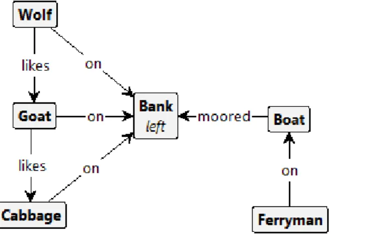
The ferryman puzzle consists of four active objects: the wolf, the goat, the cabbage and the ferryman. In the initial state of the system, the rst three objects are on the left bank of a river. The ferryman is moored to the same bank with his ferry. The goal is to transport the wolf, the goat and the cabbage to the right bank of the river without the wolf eating the goat or the goat eating the cabbage. The following rules apply.
1. The ferryman can only bring one passenger at a time.
2. If the wolf and the goat are together on either side of the river without the ferryman present, the wolf eats the goat.
3. If the goat and the cabbage are together on either side of the river without the ferryman present, the goat eats the cabbage.
GROOVE uses grammars to describe the rules of a model. The grammar describing the initial state of the ferryman model is seen in gure 1. Wolf, Goat and Cabbage are subtypes of the Cargo type. The grammars for the nal states are omitted here because they are less relevant than those shown in gures1 and2.
Figure 1: GROOVE grammar of the initial state of the ferryman model
The state space generated from this model is seen in gure 3. This state space contains 35 states and 70 transitions and is excellent for analysing state-transitions needed to get to a specic state. However, if one wants to visualize and animate the state-transitions that result in a specic state, these space generations tools don't have much to oer. GreenMirror can visualize this relatively easy.
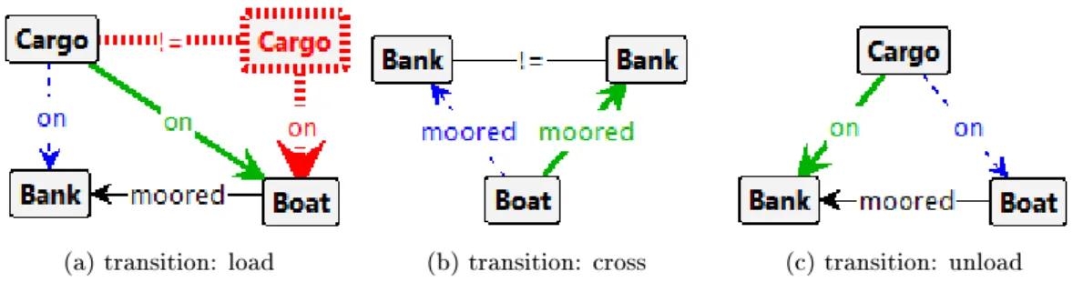
(a) transition: load (b) transition: cross (c) transition: unload
Figure 2: GROOVE grammars for state-transitions of the ferryman model. The Cargo and Bank nodes are types: they indicate any cargo or river bank, respectively, that is selected with the state-transition. After the state-transition is complete, edges with a dashed blue line are removed and those with a solid green line are created. The red node and edge means: "if Boat has no other Cargo on it."
Figure 3: GROOVE generated state space of the ferryman model, using the breadth-rst explo-ration strategy and nal states acceptor, visualized using the compact tree layout and spanning tree lter. The blocks are the unique states and the labelled lines between them are the state-transitions. Note: because of the size of the image, the states and state-transitions are practically unreadable. This does not make the image any less relevant: it's an illustration of how a state space can become unclear easily and how it can be used to for analysis.
duration of 1000 milliseconds. On lines 3 to 46, the initial state is dened: the background, the ferry, the wolf, the goat and the cabbage nodes and all relations between them are created. These lines are roughly equivalent to gure 1, with additional visualization information. Lines 49 to 58 are equivalent to gure2a. A clear dierence lies in the conditional that the ferry can not already hold a cargo node: GROOVE simply does not explore the states resulting from that state-transition, whereas GreenMirror gives an exception and aborts when this state-transition is erroneously encountered on a trace. Lines 61 to 68 and 71 to 80 are equivalent to respectively gures 2band2c.
Listing 1: example Groovy code for the ferryman model
1 i n i t i a l i z e (500 , 300 , 1000) ; 2
3 addNodes (
4 // Background .
5 new Node ("bank : l e f t ")
6 . s e t ( f x (" r e c t a n g l e ") . s e t S i z e (150 , 300) . s e t P o s i t i o n ( 0 , 0)
7 . s e t F i l l (" l i n e a r−g r a d i e n t ( to r i g h t , darkgreen 0%, l i m e g r e e n 92.5% , #00F0F0 100%)") ) ,
8 new Node (" r i v e r ")
9 . s e t ( f x (" r e c t a n g l e ") . s e t S i z e (200 , 300) . s e t P o s i t i o n (150 , 0)
10 . s e t F i l l (" l i n e a r−g r a d i e n t ( to r i g h t , #00F0F0 0%, #00 DEDE 50%, #00F0F0 100%)") ) ,
11 new Node ("bank : r i g h t ")
12 . s e t ( fx (" r e c t a n g l e ") . s e t S i z e (150 , 300) . s e t P o s i t i o n (350 , 0)
13 . s e t F i l l (" l i n e a r−g r a d i e n t ( to l e f t , darkgreen 0%, l i m e g r ee n 92.5% , #00F0F0 100%)") ) ,
14 // Ferry .
16 . s e t ( fx (" image ") . setImageFromFile (" t e s t c a s e s /img/ boat . png") 17 . setFitWidth (100) . s e t P r e s e r v e R a t i o (t r u e) ) , 18 // Cargo .
19 new Node (" cargo : goat ")
20 . s e t ( fx (" image ") . setImageFromFile (" t e s t c a s e s /img/ goat . png") 21 . setFitWidth ( 5 0 ) . s e t P r e s e r v e R a t i o (t r u e) ) , 22 new Node (" cargo : wolf ")
23 . s e t ( fx (" image ") . setImageFromFile (" t e s t c a s e s /img/ wolf . png") 24 . setFitWidth ( 5 0 ) . s e t P r e s e r v e R a t i o (t r u e) ) , 25 new Node (" cargo : cabb")
26 . s e t ( fx (" image ") . setImageFromFile (" t e s t c a s e s /img/ cabbage . png") 27 . setFitWidth ( 5 0 ) . s e t P r e s e r v e R a t i o (t r u e) ) , 28 ) ;
29
30 // R e l a t i o n s .
31 R e l a t i o n onRelation = new R e l a t i o n ("on") . setNodeB ( node ("bank : l e f t ") ) 32 . setPlacement ( Placement .RANDOM) ; 33 addRelations (
34 new R e l a t i o n ( ) . setNodeA ( node (" f e r r y ") ) 35 . setName ("moored_to")
36 . setNodeB ( node ("bank : l e f t ") ) . setPlacement ( Placement .EDGE_RIGHT) , 37 onRelation . c l o n e ( ) . setNodeA ( node (" cargo : goat ") ) ,
38 onRelation . c l o n e ( ) . setNodeA ( node (" cargo : wolf ") ) , 39 onRelation . c l o n e ( ) . setNodeA ( node (" cargo : cabb") ) , 40 new R e l a t i o n ( ) . setNodeA ( node (" cargo : wolf ") ) 41 . setName (" l i k e s ")
42 . setNodeB ( node (" cargo : goat ") ) , 43 new R e l a t i o n ( ) . setNodeA ( node (" cargo : goat ") ) 44 . setName (" l i k e s ")
45 . setNodeB ( node (" cargo : cabb") ) 46 ) ;
47
48 // T r a n s i t i o n : load .
49 addTransition ("load_ ( goat | wolf | cabb ) ", { S t r i n g cargo −>
50 i f ( node (" f e r r y ") . getRelatedNodes (−1 , "on") . ofType (" cargo ") . s i z e ( ) > 0) {
51 f a i l ("The f e r r y can only hold one cargo o b j e c t . ") ; 52 }
53 switchPlacementRelation (
54 new R e l a t i o n ("on") . setNodeA ( node (" cargo : " + cargo ) ) 55 . setNodeB ( node (" f e r r y ") )
56 . setPlacement ( Placement .RANDOM) . s e t R i g i d (t r u e) 57 ) ;
58 }) ; 59
60 // T r a n s i t i o n : c r o s s . 61 addTransition (" c r o s s ", { 62 switchPlacementRelation (
63 node (" f e r r y ") . g e t R e l a t i o n ( 1 , "moored_to") 64 . c l o n e ( )
65 . setNextNodeB ( nodes ( ) . ofType ("bank") )
66 . setNextPlacement ( Placement .EDGE_RIGHT, Placement .EDGE_LEFT) 67 ) ;
68 }) ; 69
70 // T r a n s i t i o n : unload . 71 addTransition (" unload ", {
72 f o r ( Node cargo : node (" f e r r y ") . getRelatedNodes (−1 , "on") . ofType (" cargo ") ) {
73 switchPlacementRelation (
74 new R e l a t i o n ( ) . setNodeA ( cargo ) 75 . setName ("on")
76 . setNodeB ( node (" f e r r y ") . getRelatedNode ( 1 , "moored_to") ) 77 . setPlacement ( Placement .RANDOM)
78 ) ; 79 } 80 }) ;
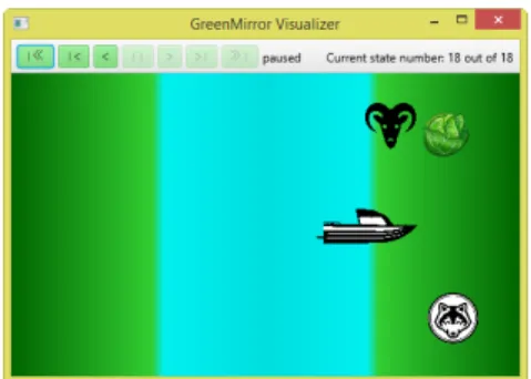
the ferryman puzzle. In gure3, it is the path starting from the initial state, shown left in the gure, and ending in the state, shown in the bottom right corner of the gure. All other nal states are unsuccessful solutions where either the goat or the cabbage gets eaten, or states that transition back into one of the displayed unique states. The trace is shown in listing 2.
Listing 2: example trace for the ferryman model
1 load_goat 2 c r o s s 3 unload 4 c r o s s 5 load_wolf 6 c r o s s 7 unload 8 load_goat 9 c r o s s 10 unload 11 load_cabb 12 c r o s s 13 unload 14 c r o s s 15 load_goat 16 c r o s s 17 unload
Figure 4: a screenshot of the by Green-Mirror visualized nal state of the fer-ryman model as dened in listings 1 and2
3 Features
Knowledge of the features of GreenMirror is imperative when using the application. The two parts GreenMirror is composed of and their usage is rst described in section 3.1. The way a model is interpreted is then elaborated upon in section3.2, followed by a description of an integral part of the visualizations in section 3.3: node placement. Further possibilities are presented by discussing all currently available commands in section3.4. Sections3.5 and 3.6briey expand upon two auxiliary functionalities: the log and the GridBuilderclass, respectively.
3.1 Client and server
The GreenMirror application is divided into two distinct components: the client and the server. The client interprets the user's model and translates it into commands. The server performs the actual visualization on the basis of these commands. Due to this decoupling, the frame-work is more maintainable and extensible and can thus be easily linked to other components or component versions.
Both components have to be executed using command line options. For the client to run, it needs a server to be available. To start the server, only one option has to be provided: the port. Use, for example, the option−−port=81 to run the server on port 81. The−−verbose option can be added to enable verbose output to the log and −−help to show all available command line options.
The client has three required options: −−host,−−modeland−−trace. If a GreenMirror server is running local on port 81, the rst option would look like −−host=127.0.0.1:81. To initialize a model using a Groovy script (which is currently the only supported model initializer), use −− model=groovyscript:<groovyle>and to select a trace using the le selector (which is currently the only supported trace selector), use−−trace=le:<tracele>. <∗le>should, of course, be replaced with the corresponding le names. Similar to the server,−−verboseand−−helpcan also be used with the client. For more details, see sections4.2to4.4.
3.2 Nodes and relations
Tools such as GROOVE [10] use nodes and edges to dene their model. This terminology can not simply be copied, because the denition and usage of an edge is slightly dierent than the equivalent entity used in GreenMirror. GreenMirror uses nodes and directional relations to dene the model. State-transitions consist of adding and removing nodes, altering the appearance of nodes and changing relations between nodes.
Node properties include a type, a name, labels and an appearance wrapper, all of which are optional. When the node is added to the model, it receives an internal identication number; "ID" for short. The user does not have to interact with this ID in any way. Nodes also store their relations with other nodes.
Each GreenMirror node that has a visual appearance needs to store and track the properties of its FX. This is internally done using implementations of the abstractFxWrapperclass. The FX type can only be dened once for every GreenMirror node. The currently supported FX types are:
• rectangle;
• circle; • text; and
• image (with a local or remote source).
Per FX type, certain properties can be set only initially and some can also be set or changed after the node's FX initialization. Due to the nature of GreenMirror, all properties of the latter type must be animatable. The opacity property, for example, is animatable by default by the JavaFX library. The width of a rectangle, on the other hand, is not animatable by default. GreenMirror includes animation support for some properties such as width so these properties can be changed during state-transitions. GreenMirror also supports the animation of some discrete properties, such as the text property of the text FX type. This is done by using a fast fade-out on the JavaFX node, changing the property and then using a fast fade-in. Support for additional FX types and FX type properties can be easily added to the framework. See section4.6and appendicesA.3andA.4.
3.3 Node placement
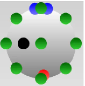
Placements are an important aspect of the visualization of nodes and their relations. They provide a level of abstraction and let the user worry rather about the model than about the actual coordinates of nodes on the visualizer. Placement relations between nodes indicate that one node of the relation, node A, is placed in a specic respect to the other node of the relation, node B. There are currently several extensions of the abstractPlacementclass implemented which are described below and are illustrated in gure 5. Every instance of Placement also has an optional position relative to the placement. For example: if a node A has an edge top placement with relative position (0, −20)on node B, node A is placed 20 pixels above (and centred on) the edge of node B.
Corner*Placement A placement on any of the corners of a JavaFX node: top left, top right, bottom right or bottom left.
Edge*Placement A centred placement on any of the edges of a JavaFX node: top, right, bottom or left.
MiddlePlacement A placement in the exact middle of a JavaFX node.
EdgePlacement A placement on the edge of a JavaFX node, according to a specied angle. An angle of zero degrees is the equivalent an edge top placement, and an angle of 90 degrees (positive) is the equivalent of an edge right placement.
CustomPlacement A placement where only the relative position data is used to determine the coordinates. The relative position data is relative to the coordinates calculated for the MiddlePlacement.
coordinates aren't recalculated every time node B moves (in the case of a rigid placement relation).
NoPlacement The default for a relation.
Figure 5: an example available placements on a circle FX node. The green circles have a corner* (or at least, what would have been the corner), edge* or middle placement, the blue ones an edge placement with -10 and 10 degrees, the black one a custom placement with relative position (−10, 0)and the red one a random placement.
3.4 Commands
In the current version of GreenMirror, communication between the client and the server is one way: all supported commands are meant to be sent from the client to the server. With the information in this section and section 4.8, one can develop a completely new client or server that can work with the current version of GreenMirror. For a better overview, the commands have been divided into tables 2 and 3: the rst is about commands relating to the visualizer and the handling of state-transitions, the second is about changes in the model. In the tables, the command name is in the upper left corner, the parameters, their type and their description on the right and the command description underneath those. This section is meant to give an overview of the currently available commands used within GreenMirror: it is not as detailed as the JavaDoc documentation that is available on the repository of this project.
Table 2: commands pertaining to the visualizer and the handling of state-transitions
Initialization width integer
The width of the visualizer window.
height integer
The height of the visualizer window.
defaultAnimationDuration double
The default time animations will take to complete.
rotateRigidlyRelatedNodesRigidly boolean
Whether the "A" node of a rigid relation should rotate rigidly when the "B" node is rotated.
SetAnimationDuration duration double The duration of all following animations, in milliseconds.
This sets the duration of all atomic animations. For example: if the animation duration is set to 1000 milliseconds and ve animations will be played sequentially, the total animation duration is 5000 milliseconds.
Flush delay double
The delay that is added after the previous animation, in milliseconds.
By default, all animations resulting from one state-transition are played parallel to each other. This command creates a new queue: the set of parallel animations created after this command are played after the set of previously created animations. Optionally, a delay can be added between the previous and upcoming set of animations. Also see section4.7.
EndTransition
This command signals the server that the state-transition has ended.
StartVisualization
The command that tells the server that the visualizations may start. The current version of this server handles this by transitioning to the rst state.
ExitVisualizer
This command communicates to the server that the visualizer should exit. In this version of GreenMirror, the client sends this command if a fatal error is encountered in the user's model.
Table 3: commands pertaining to the user's model
AddNode id integer
The unique, internal ID of the GreenMirror node.
identifier string
The identier of the GreenMirror node: the user-dened type and name.
This signals that a node has been added to the user's model. The visualizer doesn't have to do anything yet: the FX is yet to be dened at this point.
AddRelation name string
The name of the relation.
nodeA integer
The internal ID of node A.
nodeB integer
The internal ID of node B.
placement string
rigid boolean Whether the relation is rigid or not.
tempFX FxWrapper
The temporary FX of node A.
This indicates that a relation has been added between a node "A" and a node "B". If placement is set, the server should handle this. The same goes for tempFX.
RemoveNode id integer
The internal node ID.
This commands signals that a GreenMirror node has been removed from the user's model. Consequently, all relations have also been removed.
RemoveRelation id string
The unique ID of the relation.
nodeA integer
The internal ID of node A.
This commands signals that a relation has been removed. The server should also handle restoring the FX of node A in the case a temporary FX was set.
SetNodeFX id integer
The internal ID of the GreenMirror node.
fx FxWrapper
The FX values.
This commands communicates with what properties and values the FX of a node should be set. The fx parameter can include all properties that can be set, initially or otherwise (see section3.2).
ChangeNodeFX id integer
The internal ID of the GreenMirror node.
fx FxWrapper
The new FX values.
This commands indicates that the FX of a GreenMirror node has been changed. The fx parameter can include only animatable properties (see section 3.2).
3.5 Log
gure6). As was briey mentioned in section3.1, a verbose option can be enabled which results in the log being lled with more raw data.
Figure 6: an instance of WindowLoggerright after the server has been executed
3.6 The GridBuilder class
Figure 7: the result of the GridBuilder example code of listing3
GreenMirror has an auxiliary GridBuilder class created to take away the tedious work of building a grid of nodes. It supports properties such as the amount of cells, the cell width and height, cell spacing, cell colour, borders, a background colour and the type and name prex for every GreenMirror node it creates. It builds the grid by creating one GreenMirror node per cell and one for the background, all of which have the rectangle FX type. Listing3 shows an example of how short the code is to create a TicTacToe grid, in contrast to dening every single GreenMirror node, not to mention the tedious work of getting their exact positioning right. Doing the same without the GridBuilder class takes roughly 30 lines of sloppy code. The result of listing 3 is visible in gure7.
Listing 3: example code the user can use to build a grid of nodes
1 new GridBuilder (" ticTacToeGrid : c e l l _ ") 2 . setCellCount ( 3 , 3)
3 . s e t C e l l S i z e (50 , 50)
4 . s e t C e l l F i l l (" l i n e a r−g r a d i e n t ( to bottom , #FFF, #DDD) ")
5 . s e t C e l l S p a c i n g ( 5 )
6 . s e t B o r d e r S i z e ( 5 ) // top , r i g h t , bottom and l e f t 7 . s e t B a c k g r o u n d F i l l (" black ")
4 Design and implementation
This section gives more detailed information about the design of GreenMirror and some details of its implementation. GreenMirror is written with version 8 of the Java Runtime Environment and developed under Eclipse Luna. It highly depends on the integrated JavaFX library and uses JUnit [7] for testing, JOpt Simple [5] for handling the command line options (see section 4.3), Groovy [4] (see section 4.4) for its JSON implementation and scripting capabilities and the Eclipse JDT annotation package for usingNonNullannotations. GreenMirror is composed of 114 classes in 12 packages, which sums up to a total of 7429 lines of code.
4.1 Package structure
GreenMirror's package structure is fairly self-evident. Still, a short explanation per package is in place. Details about how to extend certain subpackages are available in appendix A. Corresponding class diagrams depicting all relations between the classes are unfortunately too large to be a useful addition to this report, although they are available on the repository.
greenmirror is the main package containing classes shared by the client and server. greenmirror.client contains all classes that pertain solely to the client.
greenmirror.client.modelinitializers contains all implemented model initializers that can be used by the client. See section4.4.
greenmirror.client.traceselectors contains all implemented trace selectors that can be used by the client. See section4.4.
greenmirror.commandlineoptionhandlers contains all command line option handlers, both for the client and the server. The @ClientSideand @ServerSide annotations indicate where they are used. See section4.3.
greenmirror.commands contains all commands that are sent from the client to the server and vice versa. It also contains all handlers that interpret and handle received commands. The handlers have @ClientSide and @ServerSide annotations to indicate where their respective commands are received.
greenmirror.fxpropertywrappers contains all implemented wrappers for FX properties. See section4.6.
greenmirror.fxwrappers contains all implemented FX wrappers. See sections 3.2and4.6. greenmirror.placements contains all implemented placements. See section3.3.
greenmirror.server contains all classes that pertain solely to the server.
greenmirror.server.playbackstates contains the playback states of the visualizer. See sec-tion4.5.
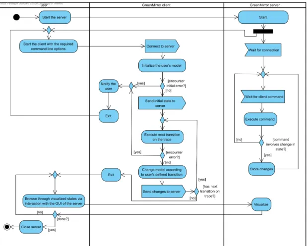
Figure 8: simplied activity diagram of the general work-ow
4.2 General work-ow
The general work-ow of a typical execution of the application is illustrated in the simplied activity diagram of gure8. This is meant to be fairly general: the exact work-ow depends on the used model initializers, the used trace selector and the user's model. In the current version, the visualization can only start when the whole model has been interpreted by the client and has been sent to the server. This behaviour is meant to ensure top performance while transitioning through the states, but can be easily modied.
4.3 Detailed work-ow
The rst thing that occurs when operating the application is starting up the client or server and parsing the command line options. GreenMirror uses the JOpt Simple library [5] to parse command line options in the same way options can be used with executables of *nix operating systems. Available command line options implement the CommandLineOptionHandler interface. This contains everything needed to handle options: option and argument specication, processing order, argument validation and option processing. See gure15(appendixB) for the (simplied) sequence of these events. From the diagram can be seen that the options are all validated before they are processed. This prevents partial processing without having all required and valid options (for example: initializing the model without a valid server address).
should be explicitly stated. The complete set of the application's functions work as a direct consequence of the processing of these options. For example: the handler for the−−hostoption handles establishing the connection to the server and the handler for the−−traceoption executes the trace. This results in the fact that new functionalities that should be executed during start-up can be easily added by implementing and adding new option handlers (see appendix A for instructions).
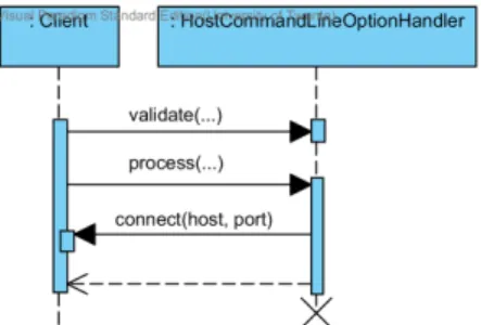
Figure 9: simplied sequence dia-gram of the handling of the −−host command line option
Next are the implemented command line option han-dlers of the client. From here on out, the assumption is made that all required options are passed (−−host, −− modeland−−trace) and that their arguments are valid. If that would not be the case, GreenMirror would have ob-served this before processing and would have notied the user before terminating, as is described in the previous paragraph. The rst option that will be processed is the −−hostoption, which connects to the server. This is very straightforward and will requires no further elaboration. See gure9.
Handling the model initializer option −−model is far
more interesting. Several notable things are worth stating when looking at the sequence diagram in gure16(appendixB). Firstly, it can be seen that multiple model initializers can be selected. This is designed this way so the user can dene the model in more than one way, perhaps even with the use of modules. In practise this can be used by simply passing the −−model option multiple times. Multiple model initializers are executed in the same order as they were passed via the command line. Secondly, a model initializer should dene the model with the initial state and the state-transitions. The initial state can be dened by dening the initial nodes and relations and adding them to the controller. This sends the information directly to the server. Each state-transition is dened as an instance of the ModelTransition class and holds a groovy.lang.Closureeld. This is code that is executed when the transition is executed and should transition the model to the next state. How the model initializer exactly denes the initial state and the state-transitions is up to the implementation (see section4.4). Finally, when the model initializers have been executed and thus the initial state has been dened, GreenMirror sends the StartVisualization command to the server, indicating that the transition to the rst state can be performed.
The−−traceoption is handled next. See gure 17 (appendixB) for the sequence diagram. This follows somewhat the same structure as the model initializer option handler, with a few slight dierences. Only oneTraceSelector can be used. However, multipleModelTransitions can be executed with each transition from the trace, due to the fact that the ModelTransition instance has a regular expression pattern that matches with zero to unlimited transitions from the trace. These transitions are executed in the order in which the model initializer added them to the controller. After each executed transition, GreenMirror sends anEndTransitioncommand to the server, indicating that a new state has been reached. If the user wants GreenMirror to refrain from sending this command, perhaps because the executed transition is part of the next one, the supplementalag of the ModelInitializer instance can be set totrue.
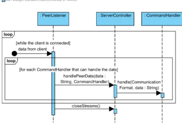
The client is now nished and will close. In the meanwhile, the server has received the commands the client has sent. Every command is passed to the correctCommandHandler in the sequence as shown in gure10. What exactly happens in thehandle(CommunicationFormat, String) method of theCommandHandler entirely depends on the received command.
Figure 10: simplied sequence diagram of the server receiving data
(gure 18in appendixB) is that all visualization parameters of the state-transition are derived from the button the user clicked on.
4.4 Interface design
This section discusses the available interfaces for tool owners that provide ways of loading models into GreenMirror, and the current implementations. Loading a model consists of two parts: dening the model and providing the trace that denes in which order state-transitions will take place. Both parts have corresponding interfaces: respectively ModelInitializer andTraceSelector.
The model initializer has a few responsibilities. First and foremost it must, in the most general sense and not surprisingly, initialize the model according to the specications of the user. More specically: it must receive information from the user about how the initial state of the model is dened and how dierent state-transitions inuence the model and the visualization. How the model initializer receives or retrieves this information is up to the implementation. Once it has received this information, it can add nodes to the client controller, remove nodes, add relations, etcetera. These changes are automatically conveyed to the server. The model initializer can also use the interface with the controller to send commands directly to the server, by use of the currently available commands in the greenmirror.commands package. This behaviour is, however, not recommended, because this circumvents the logic incorporated in updating the model via the controller. It is meant to provide the possibility to send auxiliary commands such as the SetAnimationDuration command.
The model initializers must dene which state-transitions can happen by adding new instances ofModelTransitionto the controller. As mentioned in section4.3, this class has agroovy.lang.Closure eld that changes the model when the closure is executed. This type is chosen to directly support the rst implemented model initializer, although it is not restricted to this rst implementation. The closure can accept arguments based on the transitions on the trace. This is best explained using an example. Suppose the user wants to visualize a ConnectFour game. It would be unwieldy to dene a state-transition for every possible move (although there are only seven at the most), so the user denes one state-transition that uses the regular expression^move([0−6])\$ to accept transitions from a trace. This means it needs the number of the column as an argument in the closure that executes the state-transition. Fortunately, the Groovy library supports this and GreenMirror takes advantage of this by supporting string and integer type arguments.
com-mand handlers. However, if the server is used as a visualizer, the model initializer has the responsibility of making sure the server rst receives the initialization command. Without it, there is no JavaFX stage to which JavaFX nodes can be added. A tool owner developing a new model initializer could choose to delegate this responsibility to the user.
The model initializer that has been implemented in this rst version of GreenMirror is based on Groovy [4]. Groovy is a dynamic language for the Java platform and provides a vast array of useful features. Specically, the model initializer uses Groovy's script functionalities. This choice was made due to the following reasons.
1. The user receives the power and exibility of a full-featured programming language, but still is easy to learn. This means that both advanced programmers and users without much experience can use it.
2. The user scripts can be executed during runtime, meaning that, while employing a complete programming language, the GreenMirror framework doesn't have to be recompiled every time the user alters his model.
3. A clear interface with the controller can be provided to the user, which Groovy calls a base class. The user can refer in his script to the base class' methods without referring to any object. This works as if the user is programming in the context of one of the methods of the base class (which it also comes down to, internally).
Listing 4 shows an example of a user script that can be executed by the Groovy script model initializer. Figure 11 shows a screenshot of its resulting visualization. It can be seen from the listing that chained statements are possible and actually encouraged to improve the readability of the script. Another notable advantage is that it is easily seen that calls to the base class (and thus indirectly to the controller) indicate a read from or a write to the model. For example, creating a new Nodeinstance does not mean it is added to the model: addNodes() takes care of that.
Listing 4: example Groovy script dening the user's state-transition model
1 i n i t i a l i z e (480 , 200) ; 2 addNodes (
3 new Node (" l o c : 1 ") . s e t ( f x (" r e c t a n g l e ")
4 . s e t S i z e (160 , 200) . s e t P o s i t i o n ( 0 , 0)
5 . s e t F i l l (" r a d i a l−g r a d i e n t ( c e n t e r 80px 100px , "
6 + " r a d i u s 150px , white , red ) ") ) , 7 new Node (" l o c : 2 ") . s e t ( f x (" r e c t a n g l e ")
8 . s e t S i z e (160 , 200) . s e t P o s i t i o n (320 , 0)
9 . s e t F i l l (" r a d i a l−g r a d i e n t ( c e n t e r 400px 100px , "
10 + " r a d i u s 150px , white , red ) ") ) , 11 new Node (" obj ") . s e t ( fx (" c i r c l e ")
12 . setRadius ( 2 0 )
13 . s e t F i l l (" l i n e a r−g r a d i e n t ( to bottom , limegreen , black ) ") )
14 ) ;
15 addRelation (
16 new R e l a t i o n ("on") . setNodeA ( node (" obj ") ) 17 . setNodeB ( node (" l o c : 1 ") )
18 . setPlacement ( Placement .MIDDLE) 19 ) ;
20
21 addTransition (" switch ", { 22 switchPlacementRelation (
23 node (" obj ") . getPlacementRelation ( ) . c l o n e ( )
24 . setNextNodeB ( nodes (" l o c : ") ) 25 ) ;
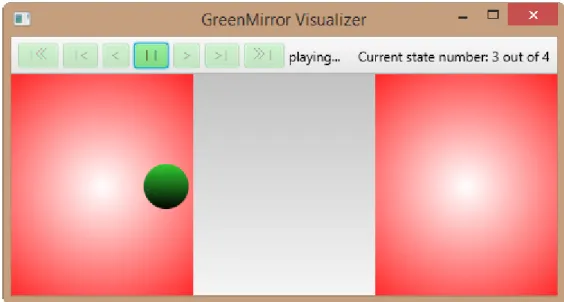
Figure 11: a screenshot of the executing visualization of listing4 with the trace from listing5
After the model initializer has set the initial state and saved allModelTransitions, the selected TraceSelector is executed. The current FileTraceSelector implementation retrieves the trace from a text le where the transitions are separated by a newline. In the visualization example of gure11, the trace le looked like listing5. In the toolbar of gure11a state count of four can be seen, while three transitions are in the trace. This is naturally because the initial state is included in the count.
Listing 5: example trace le for the model dened in listing4
1 switch 2 switch 3 switch
Both the ModelInitializer andTraceSelectorinterfaces accept one argument from the command line. This should be the source of the model and the trace, respectively. InGroovyScriptModelInitializerit is the le name of the Groovy script, while in FileTraceSelectorit is the name of the le containing the trace. In future implementations that, for example, connect GreenMirror to another tool, this could be the name of the model.
4.5 Implemented design patterns
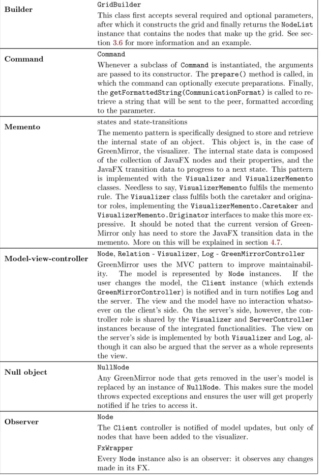
Table 4: design patterns used in the GreenMirror framework
Builder GridBuilder
This class rst accepts several required and optional parameters, after which it constructs the grid and nally returns the NodeList instance that contains the nodes that make up the grid. See sec-tion3.6for more information and an example.
Command Command
Whenever a subclass of Command is instantiated, the arguments are passed to its constructor. The prepare() method is called, in which the command can optionally execute preparations. Finally, the getFormattedString(CommunicationFormat) is called to re-trieve a string that will be sent to the peer, formatted according to the parameter.
Memento states and state-transitions
The memento pattern is specically designed to store and retrieve the internal state of an object. This object is, in the case of GreenMirror, the visualizer. The internal state data is composed of the collection of JavaFX nodes and their properties, and the JavaFX transition data to progress to a next state. This pattern is implemented with the Visualizer and VisualizerMemento classes. Needless to say, VisualizerMemento fulls the memento rule. The Visualizer class fulls both the caretaker and origina-tor roles, implementing the VisualizerMemento.Caretaker and VisualizerMemento.Originator interfaces to make this more ex-pressive. It should be noted that the current version of Green-Mirror only has need to store the JavaFX transition data in the memento. More on this will be explained in section 4.7.
Model-view-controller Node, Relation - Visualizer, Log - GreenMirrorController GreenMirror uses the MVC pattern to improve maintainabil-ity. The model is represented by Node instances. If the user changes the model, the Client instance (which extends GreenMirrorController) is notied and in turn noties Log and the server. The view and the model have no interaction whatso-ever on the client's side. On the server's side, howwhatso-ever, the con-troller role is shared by the Visualizer and ServerConcon-troller instances because of the integrated functionalities. The view on the server's side is implemented by both Visualizer and Log, al-though it can also be argued that the server as a whole represents the view.
Null object NullNode
Any GreenMirror node that gets removed in the user's model is replaced by an instance of NullNode. This makes sure the model throws expected exceptions and ensures the user will get properly notied if he tries to access it.
Observer Node
The Client controller is notied of model updates, but only of nodes that have been added to the visualizer.
FxWrapper
Prototype FxWrapper, Placement
All implemented subclasses are instantiated using the built-in java.util.ServiceLoader injector. When a new instance of FxWrapper or Placement is requested based on a data string, the string is compared to the stored instances and if a match is found, a clone of the matched instance is returned. Placement imple-mentations can also be instantiated using the new operator, but both FxWrapper and Placement are at some point constructed via the prototype design pattern.
Proxy FxWrapper
The FxWrapper class is exactly what the name says: a wrapper for the FX of a GreenMirror node. It generalizes handling the FX and provides intelligent access to certain FX properties.
FxPropertyWrapper
The FxPropertyWrapper implementations primarily provide in-telligent access to several methods that are often used. It is added to simplify adding support for dierent FX types and properties.
State PlaybackState
The visualizer has a nite set of playback states it can be in. Certain things depend on the visualizer's playback state, such as which of toolbar buttons are enabled. The context role is taken up by the Visualizer instance, whereas the playback state is rep-resented by instances of implementations of the PlaybackState class. Figure 12 shows the state machine diagram belonging to the playback states.
Strategy CommandHandler,ModelInitializer, TraceSelectorCommandLineOptionHandler, FxWrapper, All classes that implement the strategy design pattern do this so their subclasses can handle data in their own way. Which strategy (and thus which subclass of one of the above classes) is passed is determined at runtime. For example: every ModelInitializer implementation has its own executeInitializer() method that initializes the user's model in its own way. Which ModelInitializer is executed, depends on which the user se-lects during runtime. The Log class also uses this pattern, only it accepts PrintStream subclasses as strategies.
4.6 Internal representation of visual node properties
TheFxWrapperclass and its subclasses store and track the FX properties of GreenMirror nodes, as is explained in section3.2. Using a wrapper instead of directly using a JavaFX node instance has the following reasons.
1. FxWrapper provides general methods such as converting FX data into an object that can be shared between client and server, or changing general properties like the rotation and opacity of a JavaFX node.
2. The implementations of abstract methods ofFxWrapper used by GreenMirror might dier per type of JavaFX node. For example: the calculations of a specic placement on the edge of a circle dier from the calculations of a placement on the edge of a rectangle. 3. For the logic in the user's model and the proper creation of state-transitions on the server,
properties have to be set and changed during the processing of state-transitions in the model without directly aecting the FX in the visualizer. As will be explained in section 4.7, changing actual properties of JavaFX nodes happens as a consequence of the execution of JavaFX transitions. To work with these values without directly visualizing them, a wrapping layer is needed providing 'virtual' values.
4. Support for new types of JavaFX nodes can be easily added. Examples include ellipses, three-dimensional shapes and composite nodes.
The way FxWrapper converts its properties to an object that can be sent over the network, is generalized in the sense that support for new types of properties can also be implemented easily. The following example will clarify this. One of the supported properties ofImageFxWrapperis the X coordinate of typedouble. In the current GreenMirror version, FX data is sent to the server in JSON format (see section4.8). The value of the X coordinate can be easily converted to and from a string format, as would the boolean-typepreserveRatio property. So how would theimage property of type javafx .scene.image.Image be converted to and from a valid JSON string? The implementations ofFxPropertyWrapperhandle the FX properties to make this modular and easily extensible. In the case of the example about the image, the ImageFxProperty class handles the image property.
4.7 Internal representation of states and state-transitions
Figure 13: an example of one stored state-transition in JSON notation State data is not stored in the current version of
Green-Mirror, because it is unnecessary. To understand why this is, an explanation must be provided about how state-transition data is stored and how JavaFX handles its tran-sitions (animations, in this case).
ParallelTransition instances (separated by aPauseTransitionto incorporate an optional delay) which in turn hold the individual Transitioninstances that animate the change in properties. Initially, every change in the model the server receives ends up in the same top-level ParallelTransition. The user might want to show several sequential animations during one state-transition. For this scenario, the ush command has been implemented. This results in the server creating a new ParallelTransition instance in the root SequentialTransition in which all further transitions will be stored. For an example of these nested transitions of one state-transition, see gure13. JavaFX' transition classes also have another interesting functionality: the rate property. When set to a negative value, the animation reverses. This makes browsing backwards through the model's states very easy and removes the need to recalculate FX property values of JavaFX nodes.
These reasons make storing state data unnecessary. State-transition data is composed of the JavaFX animations needed to go from one state to another, including the start and end values of the relevant FX properties, whichever direction the user wants to go.
4.8 Interchange formats
Nothing is currently being stored of the result of a visualization. The formats associated with dening the user's model and the corresponding trace are discussed in section 4.4. This leaves the protocol used between the client and the server. This is very simple and has the form command:commanddata. The part before the colon holds the name of the command as it is presented in section 3.4. This is included so the receiver knows which CommandHandler imple-mentation can handle the command data. The part after the colon holds the command data, formatted in the selectedCommunicationFormat. The JSON format is currently the only supported format. An example of a command is shown in listing6.
Listing 6: an example command sent from the client to the server in the JSON communication format, indicating that a node as been added to the model
5 Validation
Unit tests have been written with the JUnit library that validate the classes the user works with the most: Node,Relation, NodeList, RelationList, FxWrapper, FxWrapper's subclasses, Placement andPlacement's subclasses. The unit tests include the various ways of instantiating new objects, calling their methods with extreme values and in the case of thePlacementtests, they verify the calculations made to place a node in a certain respect to another node. These tests all worked as expected.
Due to the visual nature of GreenMirror, further verication is based on an extensive system test, written for use with the Groovy script model initializer. This test also works to some extent as a unit test: it tests several classes and specic functionalities. Furthermore, it showcases and explains how certain functionalities work and how they can be used. Among other sub-tests, it tests the following:
• setting the duration of animations;
• using parameters from state-transition names;
• adding nodes;
• setting the FX of nodes;
• altering the general properties of nodes;
• altering properties specic for shape nodes (rectangle, circle and text nodes);
• altering properties of a rectangle node; • altering properties of an image node;
• altering properties of a text node;
• adding and removing simple relations between nodes;
• adding and replacing placement relations;
• using rigid placement relations;
• using chained, rigid placement relations; and
• removing nodes.
A coverage of 84.8% has been achieved with all tests combined. GreenMirror uses the@NonNull annotation with elds and method arguments and return types. Not all sub-packages of Java formally guarantee that they return a non-null object (although they do informally), resulting in several non-null checks that are eectively futile and practically non-reachable code.
Table 5: test case results
Test case lines
of code
trace
length init.time2 notable visualizations and used func-tionalities
Ferryman 109 20 ≈48 s Parametrized state-transition names,
rect-angle FX types, image FX types, node resiz-ing, node rotation, node removal, placement relations, rigid placement relations, non-placement relations, relation renon-placements, colour gradients
ConnectFour 91 10 ≈ 8 s Parametrized state-transition names,
rect-angle FX types, circle FX types, text FX types, node grid generated with GridBuilder, node creation during state-transition, colour gradients, font size set-ting, placement relations, relation replace-ments, complex model logic (determining the cell number from the column number), model failing (if an invalid move is encoun-tered on the trace), altering animation du-ration
Dining Philosophers 132 15 ≈10 s Parametrized state-transition names,
cir-cle FX types, image FX types, image al-teration during state-transition, node rota-tion, placement relations, non-placement re-lations, relation replacement, model failing (if an impossible state-transition is encoun-tered)
The following list discusses how each requirement and use case is implemented and validated, in the same order as they were dened in section1.4.
Requirement1 and use case1
The framework is easily extensible due to the use of interfaces and abstract classes. One example is the FxWrapper class: support for new FX elements can be easily added by extendingFxWrapper. Also, the use of common design patterns makes extension more easy. See appendixAfor a full list of extensible parts.
Requirement2
The use of common design patterns, extensive documentation and the use of the checkstyle plugin of Eclipse are the primary means of making the framework maintainable. Especially the model-view-controller pattern is important because it tells which classes are responsible for what. More details on the design patterns can be found in section4.5.
Requirement3 and use cases2and 3
(a) ConnectFour (b) Dining Philosophers
Figure 14: screenshots of two of the test cases
depends on the ModelInitializer implementation how this source is given (for example: a le name or a model name).
Requirement4 and use case4
The user can pass his choice for the trace source via the command line and gets handled by theTraceCommandLineOptionHandlerclass. The user's chosenTraceSelectorimplementation then retrieves the trace and that is how the application becomes aware of the trace. Requirements5 to 10and use case 5
A few examples of where the validation of these requirements is visible (as seen in gures4, 14aand14b): the ConnectFour test case visualizes rectangles, circles (requirement6) and text (requirement 7); the ferryman test case visualizes images (requirement 8); and the dining philosophers test case visualizes the placement of nodes with respect to other nodes (requirement 10). All test cases visualize simple animations (requirement 9), which of course is not visible in the gures. The fact that these test cases can be visualized validates requirement5and use case5.
Requirement11 and use case 6
This is implemented by theLogclass, as is discussed in section3.5 and visible in gure6 (page18).
Requirement12 and use case 7
Browsing from state to state is implemented by use of a toolbar with navigation buttons. The workings of these buttons are handled by the Visualizercontroller in cooperation with thePlaybackStateimplementations andToolbarButtonclass. Section4.5discusses the playback state and its eect on the toolbar buttons. The buttons are also visible on any of the screenshots of GreenMirror in this report.
Requirements13 and 14
6 Discussion
GreenMirror is the second step in the development of an extensive research tool. The work of Aalbertsberg [1] was the rst step, although except for minor design choices such as the programming language and the client-server structure, his work bears virtually no resemblance to the current version.
The intention for using a proper framework design was present during the design phase. Examples include the work of Fayad & Schmidt [3] and Markiewicz & De Lucena [9], but this has crept unwittingly into the background during the implementation phase. Some concepts have been used (e.g. hot spots), but more research should be used while further developing the GreenMirror framework. A somewhat similar point applies to the use of the MVC pattern. It is implemented, as discussed in section4.5, but there is room for improvement to increase the framework's maintainability. For example: the distinction between the controller and view roles on the server side could be made more apparent and the view role on the client side could be improved beyond the use of just theLogclass.
Help from work relating to GreenMirror's way of visualization could not be uncovered. Due to the absence of related work backing the used visualization approach, this is a point of dis-cussion. "Visualization approach" here means: the way of visualization (nodes and their FX representation) and the internal representation, which are discussed in sections3.2,4.6and4.7. I believe the current approach is optimal for the requirements set for this project. It makes sure state-transitions can take place smoothly and without delay. It would probably, however, not be suciently ecient when GreenMirror is developed beyond the scope of this project. As is discussed in section5, it can take GreenMirror nearly a minute to convert a simple model to a visualization. That model had merely 20 state-transitions. Therefore, my rst recommendation is to evaluate the current programmed structures and internal representations.
There is currently aTraceSelectorimplementation in development by the Formal Methods and Tools research group of the University of Twente to select a trace from the GROOVE application. A next improvement to GreenMirror could be the development of a ModelInitializer implementa-tion that can load a model from an existing GROOVE Grammar. This would narrow the bridge between the two tools and would certainly be considered a useful functionality. The user might be required to provide extra information about how GROOVE's nodes should be represented on the visualizer, should such an implementation be developed. Fortunately this can be done rather simple: the user can provide a script that uses the Groovy script model initializer to supplement the model, which is possible because the use of multiple model initializers is supported.
To conclude this report, some thoughts must be given about the ultimate goal of this tool. In addition to generating visualizations from a dened model, the ultimate goal is, as is briey mentioned in section1.4, generating a model denition from of user interaction with visualiza-tions.
Take a model where a state-transition results in the movement of a node from one location to another. A next extension of GreenMirror could allow the user to drag a node in the visualizer from one location to another. Assuming both location boundaries have been properly dened, the application can recognize this as a state-transition. In this scenario the user can alter the trace, adding state-transitions before, in-between or after the transitions on the original trace.
might work ne solely for recognizing state-transitions, but this still has considerable limitations in the creation of new state-transitions.
The next step is the addition of the creation of model logic. In the GreenMirror application, a transition in the model could be dened as such: "if node A and node B both have a relation with node C, remove the relation between node A and node C and add a new relation between node A and node D". In this step of the development of this extension, a user should be able to create such logic based on his interactions with the visualizer. This can become complex very fast, but that should be considered an interesting challenge to accept in the future.
The next and perhaps nal step is to make a two-way connection with other tools that enable or facilitate the research of state-transition models in dierent ways. When the connection is made between interactions with the visualizer and the creation of state-transition logic, this could be translated into a format that can be accepted by other tools. This way, the need is eliminated for researchers to rewrite their models into tool-specic formats when dierent tools are used.
References
[1] A. Aalbertsberg. Dynamic visualization of state transition systems. https://github.com/ Vaeil/StateTransAnimation/blob/master/report/report.pdf, 2015.
[2] E.W. Dijkstra. Co-operating sequential processes. F. Genuys (ed.): Programming Lan-guages, pages 43112, 1968.
[3] Mohamed Fayad and Douglas C. Schmidt. Object-oriented application frameworks. Com-mun. ACM, 40(10):3238, October 1997.
[4] Groovy: A multi-faceted language for the java platform. http://groovy-lang.org/. [5] P. Holser. JOpt simple: A java library for parsing command line options.https://pholser.
github.io/jopt-simple/.
[6] M. Huth and M. Ryan. Logic in Computer Science: Modelling and Reasoning about Systems. Cambridge University Press, 2004.
[7] Junit: a simple framework to write repeatable tests. http://junit.org/. [8] P. Kuchana. Software architecture design patterns in Java. CRC Press, 2004.
[9] Marcus Eduardo Markiewicz and Carlos J. P. de Lucena. Object oriented framework devel-opment. Crossroads, 7(4):39, July 2001.
[10] A. Rensink. The GROOVE simulator: A tool for state space generation. Applications of Graph Transformations with Industrial Relevance, pages 479485, 2004.