warwick.ac.uk/lib-publications
A Thesis Submitted for the Degree of PhD at the University of Warwick Permanent WRAP URL:
http://wrap.warwick.ac.uk/78601 Copyright and reuse:
This thesis is made available online and is protected by original copyright. Please scroll down to view the document itself.
Please refer to the repository record for this item for information to help you to cite it. Our policy information is available from the repository home page.
Analysis for Structures of Pultruded
Profile
Zheng
)
Youxin
Thesis
submitted to the University of Warwick
for
the
degree of Doctor
of Philosophy
Department of Engineering
University of Warwick
Dedicated to
my parents,
This thesis concerns a study including testing, analysis and design on beam-to-column connections for the frames of pultruded glass fibre reinforced plastic profiles. The research consists of the two principal aspects of a laboratory test programme to determine connection behaviour and the formulation of a plane frame analytical tool to determine the effect of real connection on frame behaviour.
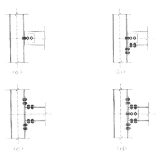
The laboratory tests involved three different 10 inch beam-to-column connections which can be categorised as having a moment-rotation behaviour that is pinned. These connections had web cleats and the method of connection was by bolting, or bolting combined with adhesive bonding. The test configuration had a central column and two beams in a cruciform arrangement. Loading was applied at the ends of the cantilever beams in such a way that the two identical connections experienced the same moment and shear force. The non-linear moment-rotation characteristics for the connections were determined and the modes of failure established. Another four tests were conducted on different 8 inch beam-to-column connections which can be categorised as being semi-rigid. Two of these connections used steel cleats for the top and bottom seat cleats while the other two had these pieces manufactured of pre-preg glass FRP using a pressure moulding process. The details and the results of these connection tests are presented.
The results of the three tests on pinned connections confirmed conclusions previ-ously reported on similar tests where the beams and column were of the 8 inch wide flange profile. The current practice of recommending that the cleated webs have combined bonding and bolting is shown to provide little additional benefit over that when the connection is bolted.
It is found that a semi-rigid connection with an acceptable moment-rotation be-haviour can be obtained using steel angles for the connection pieces. One of the two 'all' FRP connections was also found to have an acceptable moment-rotation char-acteristic but would be too complicated for real applications. The search therefore continues for the all FRP connection details giving suitable connection behaviour. Combining the results from these experiments and the analysis of the failure modes,
a number of futuristic connection designs are proposed. They include a thin shell cleat piece with curvature to increase its stiffness, six connection details using pieces that connect together by interlock and bonding (this approach reduces the need for bolting) and a radically novel system which does not mimic current steelwork prac-tice.
A new analytical method is presented which predicts the static response of non-linear elastic plane frames of polymeric composite members. Options allow for horizontal and vertical loading, second-order deflections and connections with non-linear moment-rotation characteristics. The matrix stiffness method uses a new approach to cope with the real connection behaviour. The other novel aspects of the analysis are shear deformable members and new stability functions which account for the shear deformation when determining second-order deflections. A number of new (<p) functions are derived to group the new stability functions, and these can readily be employed in the computing analysis. The analysis is successfully benchmarked against known semi-rigid frame problems of steelwork and with the limited results from a single experiment on a pultruded single bay frame. A serviceability beam line is presented for beam design and a moment equalized connection stiffness is obtained.
Two unbraced and one braced frame problems are analysed in a parametric study to determine the effect on frame response of having connections with various properties. Live loading is vertical with a horizontal component. Results of overall sway deflection showed how the frames respond when the connection properties are changed from pinned, through semi-rigid, to fully fixed. The sensitivity of the connection stiffness on the overall frame behaviour is demonstrated by the sway and the midspan deflections results, and by the moment distribution in the members. The analysis is shown to provide useful information in our quest for the optimised connection design and their performance when viewed as an integral part of a whole frame.
To establish which connection details are best suited to pultruded frame con-struction recommendations for further research and development work are given.
Abstract
Acknowledgement
XVIll...
Declaration
XIX.
Publications
XXNotations
XXI.
1 Introduction 1
2 Introduction to Polymeric Composite Materials and Their
Appli-cations 4
2.1 Introduction .
...
42.2 History of Polymeric Composites 5
2.3 Advantages of Polymeric Composites 8
2.4 FRP Pultruded Composite Profiles 9
CONTENTS
2.6 Applications . . . .
2.6.1 General Applications of Polymer Composites.
2.6.2 Structural Engineering Applications.
2.7 Conclusions . . . .
3 Literature Review on Connections in Polymer Composite
Struc-tures
3.1 Introduction
3.2 Study of Pultruded Members
3.3 Connection Research . . . . .
3.3.1 Adhesively Bonded FRP Connections
3.3.2 Bolted Plate-to-plate Connection . .
3.3.3 Review on Pinned Beam-to-column Connection
3.3.4 Semi-rigid Beam-to-column Connection
3.4 Study of Pultruded Frames.
3.5 Summary . . . .
4 Experimental Investigation on Pinned Beam-to-column
Connec-tions
4.1 Introduction
...
4.2 Description of Connection Specimens
4.2.1 Connection Wmjl0_bt
..
4.2.2 Connection Wmjl0_bt+bd
4.2.3 Connection Wmnl0_bt
..
4.3 Material Specification and Connection Details .
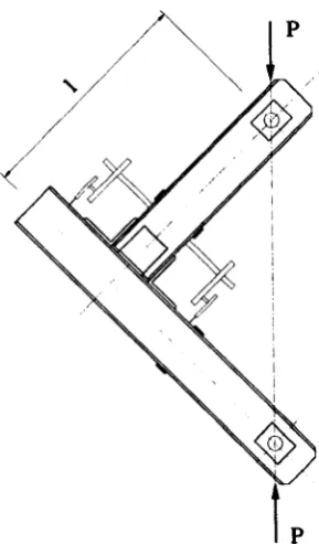
4.4 Test Method. . . .
4.4.1 Test Equipment and Loading Set-up
4.4.2 Test Measurement and Data Processing. 69
4.4.3 Methods of Testing 70
4.5 Descriptions of Tests
...
714.5.1 Test of Connection Wmj10_bt 71
4.5.2 Test of Connection Wmj10_bt+bd . 75
4.5.3 Test of Connection Wmn10_bt . . . 77
4.6 Discussion and Analysis of the Test Results 81
4.7 Conclusions from the Pinned Beam-to-column Connection Tests 88
5 Experimental Investigation on Semi-rigid Beam-to-column
Connec-tions 91
5.1 Introduction
...
915.2 Connection Description . 93
5.2.1 Connection STmj 94
5.2.2 Connection STmn . 95
5.2.3 Connection Tmj . 96
5.2.4 Connection TLmj 98
5.3 Material Specification. . 100
5.4 Manufacture of Pre-preg Cleats · 102
5.5 Testing Techniques
. . .
· 1055.5.1 Test Equipment and Loading Arrangement . · 105
5.5.2 Methods and Procedure of Test · 105
5.5.3 Test Measurement · 106
5.5.4 Data Processing . · 108
5.6 Descriptions of Tests
..
· 1095.6.1 Test of Connection STmj . · 109
CONTENTS lV
5.6.3 Test of Connection Tmj · 122
5.6.4 Test of Connection TLmj · 126
5.7 Discussion and Analysis of the Test Results · 132
5.8 Benefits of Semi-rigid Connections. · 142
5.9 Conclusions
. . .
· 1466 Conceptual Design of Beam-to-Column Connections for Pultruded
Frames 148
6.1 Introduction · 148
6.2 Thin Shell Cleat. · 149
6.3 Beam-to-column Connections · 152
6.3.1 Connection No. 1 · 153
6.3.2 Connection No. 2 · 154
6.3.3 Connection No. 3 · 155
6.3.4 Connection No. 4 · 155
6.3.5 Connection No. 5 · 156
6.3.6 Connection No. 6 · 158
6.4 Structural System Concept . · 158
6.5 Summary
. . .
· 1627 The Computer Analysis of Plane Frame Structures 165
7.1 Introduction . . . · 165
7.2 Sign Conventions and Axes . · 166
7.3 Matrix Stiffness Method · 167
7.4 Semi-rigid Connection · 168
7.4.1 Analysis of the Performance of Semi-rigid Connection · 169
7.5
7.4.3 Member-end Rotation 7.4.4 Member-end Forces 7.4.5 Static Equilibrium 7.4.6 Solution Method
7.4.7 Member End Rotation ~
7.4.8 Beam Analysis
...
Effect of Shear deformations 7.5.1 Shearing deformations 7.5.2 Bending deformations 7.5.3 Total Slope of the Beam 7.5.4 Total Deflection of the Beam. 7.5.5 Derivation of Member End Forces· 172 · 173 · 176 · 177 179
· 180 · 185 · 186
· 187 · 188 · 190 · 191 7.5.6 Effect of Semi-rigid connection and Member Shear Deformations 193 7.6 Stability Functions Used in the Matrix Displacement Method. . 197
7.6.1 Stability Functions without Shear
7.6.2 Stability Functions with Shear . .
7.7 Sum of Effect of Axial loading, Shearing and Semi-rigid. 7.7.1 Member without Pinned Connection . . .
7.7.2 Member with One End Pinned Connection
7.8 Load between Joints . . . . 7.8.1 Partial Distributed Load 7.8.2 Vertical Concentrated Load 7.8.3 Axial Concentrated Load . 7.9 Computer Program . . .
7.9.1 Program Procedure.
7.9.2 Moment-rotation Stiffness k
7.9.3 Iteration Process and Convergence Problems
· 197 · 199 .206 .206 .208
· 210 .211
· 212 · 214 .215
CONTENTS
8
7.10 Comparison of Analysis Results with Other Researches
7.11 Conclusions . . . .
Frame Analysis and Parametric Studies
8.1 Introduction...
Vl
. 219
.226
227
.227
8.2 Effect of Connection Stiffness and Member Shear Deformation . 228
8.3 8.4 8.5 8.6 8.7 8.2.1 8.2.2 8.2.3
Frame Data . . . .
Determination of Distributed Load w
Lateral Deflection of the Frame .
8.2.4 Mid-span Deflection of the Beam
Sensitivity of Frame Behaviour to Connection Stiffness
Effect of Connection Flexibility, Member Stiffness and Load
8.4.1 Influence of Connection Stiffness and Load . . . .
8.4.2 Influence of Connection Stiffness and Member Stiffness
Ultimate Connection Moment and Rotation . . . . . . .
Analysis of Pultruded Frames with Various Connection Properties
Conclusion .
. . .
9 Conclusions
9.1 Conclusions . . . .
9.1.1 Nominally Pinned Connection
9.1.2
9.1.3
Semi-rigid Connections
Analytical Modelling
9.2 Future Work. . . .
A The Detail of Pinned Beam-to-column Connections
B The Detail of Semi-rigid Beam-to-column Connections
.229
· 231
.232
.235
.237
· 241
· 241
C A Guide for Using Frame Structure Analysis Programme sframe282
C.l How to Use the Programme . . . 282
C.2 Assumptions and Sign Convention. . 283
C.3 Units. . . 284
C.4 Preparation of Data File . 285
C.4.l Basic Frame Specification Data . 285
C.4.2 Element Properties . 286
C.4.3 Boundary Condition . 287
C.4.4 Loads . . . . 287
C.4.5 Tolerance of Moment and Maximum Number of Iterations . 288
C.4.6 Semi-rigid Connection Data . 289
C.5 Output Results . 291
C.6 Examples . . . . 293
C.6.l Example 1 . 293
C.6.2 Example 2 . . 295
C.6.3 Example 3 . . 296
C.6.4 Example 4 . . 298
C.6.5 Example 5 . . 299
C.7 Computer Programme of Frame Analysis . 300
List of Figures
2.1 GRP dome structure in Benghazi (Hollaway, 1978). . . 6
2.2 GRP roof structure of Dubai Airport (Hollaway, 1978). 6
2.3 Typical pultrusion process used. . . 10
2.4 Three EXTREN series: Series 500 (left) Series 525 (center) Series 625
(right). . . 10
2.5 Exploded view of pultruded composite. 11
2.6 First B-2 aircraft during flight testing. (Courtesy U.S.Air Force.) 14
2.7 H.M.S. Wilton, a minehunter whose hull is virtually all glass fabric
and polyester resin. . . 15
2.8 Composite French Renault Espace. 16
2.9 GRP domes at Sharjah International Airport 1977 (Leggatt, 1984). 17
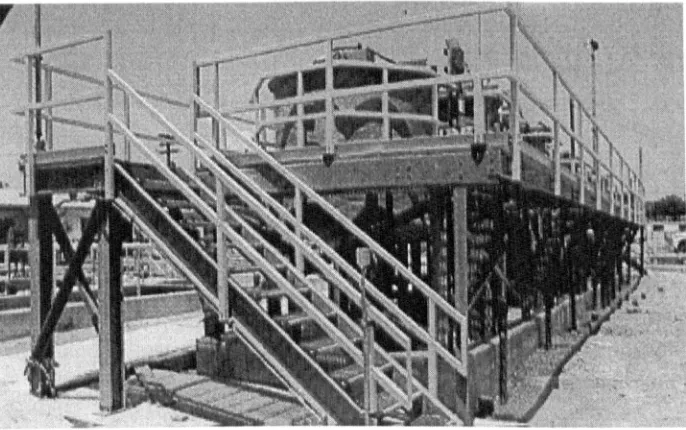
2.10 Support structure and handrail of this platform surrounding chemical
storage tanks are EXTREN. . . .. 18
2.11 Pultruded glass fibre EXTREN platform for a petrochemical complex. 19
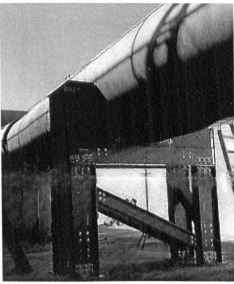
2.12 FRP supports for FRP pipes, image from MMFG Profile, Fall 1996. 20
2.13 Miyun highway bridge in China 1982. . . . 21
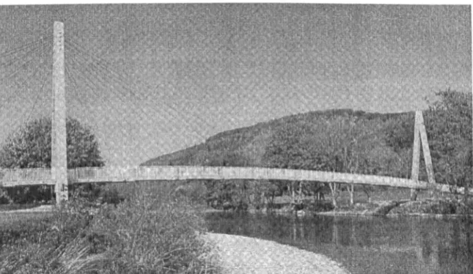
2.14 GFRP cable-stayed bridge in China 1986. 21
2.15 Composite turret at top of the Sun Bank building in Orlando, Florida
(Photo courtesy of MMFG) . . . 22
2.16 Fibreglass pedestrian bridge in Philadelphia 1993. . . 23
2.17 Glass fibre reinforced plastic motorway message sign gantries. 24
2.18 Advance composite bridge enclosures (Anon, 1997). 25
2.19 Aberfeldy footbridge Scotland, UK 1992. . . 25
2.20 Bonds Mill lift bridge Gloucestershire, UK 1994. 26
2.21 Fiberline cable-stayed bridge, Denmark 1997. . . 27
2.22 Longest stress-ribbon footbridge in Japan 1996. 28
3.1 Failure modes of an adhesively bonded joint (Hollaway, 1993). 34
3.2 Failure modes of bolted connections, (a) joint nomenclature; (b)
no-tation; (c) joint failure modes (Hollaway, 1993). 36
3.3 Effect of bolt hole clearance on ultimate load. 40
3.4 Web cleated connections, (a) Bank et al. (1990), (b) Mottram (1994). 43
3.5 Experimental set-up (Bank et al. 1990). . . . 44
3.6 Pultruded FRP beam-to-column connection (Bank et al., 1990). 48
3.7 Pultruded FRP beam-to-column connection (Bank et al., 1992). 50
3.8 Connection details (Bass & Mottram, 1994). . . 52
3.9 The beam-to-column connections (Bank et al., 1996). 54
3.10 Mosallam's universal connector and beam-to-column connection
(Mos-allam et al., 1994 a). . . . . . 55
3.11 The diagonal cracks in the VC connector. . 56
3.12 The cruciform plate connection (Turvey and Cooper, 1996 a, 1996 b). 57
3.13 Pultruded GRP frame layout (Turvey, 1996). . . 59
4.1 Configuration of connections WmjlO_bt and WmjlO_bt+bd. 64
4.2 Configuration of connection WmnlO_bt. . 66
4.3 Test arrangement and loading set-up. 68
LIST OF FIGURES
4.5 Moment-rotation curves of WmjlO_ht . . . .
4.6 Moment-rotation curves of WmjlO_bt (without slip) ..
x
72 73 4.7 The deformation of connection WmjlO_ht at failure. . 74 4.8 Ultimate failure mode of left side connection of test WmjlO_ht. 75
4.9 Moment-rotation curves of WmjlO_bt+bd . . . .
4.10 The deformation of connection WmjlO_bt+bd at failure.
76 78 4.11 Ultimate failure mode of left side connection of test WmjlO_ht+hd. 78 4.12 Moment-rotation curves of WmnlO_ht. . . . . . 79 4.13 Moment-rotation curves of WmnlO_bt (without slip). 80 4.14 The deformation of connection WmnlO_ht at failure. . 80
4.15 Ultimate failure mode of right side connection of test WmnlO_ht. 81 4.16 Piece-wise moment-rotation curves. . . . . 82
4.17 Load and mid-span deflection comparison of the beam with different beam-end connections. . . .
...
885.1 Configuration of connection STmj. 94
5.2 Configuration of connection STmn . . 96
5.3 Configuration of connection Tmj. 97
5.4 Bonding in of connection Tmj. 98
5.5 Configuration of connection TLmj. 99
5.6 Application of the adhesive to cleats for connection TLmj. · 100
5.7 The detail of steel mould for pre-preg cleat. · 103
5.8 The uncured pre-preg cleat in the steel mould. · 104 5.9 The transducers arrangement for the tests on connection STmj. .107 5.10 The transducers arrangement for the test on connection STmn. · 107
5.13 The deformation of connection STmj and the deflection of the beams. 111 5.14 Moment-strain curves for the steel cleats in connection STmj.
5.15 Strain-rotation curves for the cleats in connections STmj.
5.16 Moment-slip curves for connection STmj. . . . . .
5.17 Moment-strain curves for the column bolts in connection STmj.
5.18 Moment-rotation curves for connection STmn.
5.19 Failure of the right-side beam in connection STmn.
5.20 Failure mode of the right-side beam in connection STmn.
5.21 Final deflection of the beams in connection STmn. . . . .
5.22 Moment-strain curves for the cleats of connection STmn . .
5.23 Strain-rotation curves for the cleats of connection STmn.
5.24 Moment-slip curves for connection STmn . . . .
5.25 Gap between the top cleat and right-side beam in the test of connec-tion STmn . . . .
5.26 Moment-rotation curves for connection Tmj . .
5.27 Moment-slip curves for connection Tmj. . ..
5.28 Moment-rotation curve of connection Tmj (without slip) .. 5.29 Deformation of specimen with connection Tmj.
5.30 Moment-rotation curves of TLmj . .
5.31 Crack on pre-preg cleat. . . . . ..
5.32 Deformation of connection TLmj at the end of the test.
5.33 Ultimate connection failure due to thread stripping of the composite · 112 · 113 114
115
· 116 · 117 118 118
119 120
· 121
· 121 · 122
· 123 · 124 · 126 · 127 · 129 130
bolt. . . . . 130 5.34 Cracking along the interface of the web and the flange of the column. 131 5.35 Moment-rotation curves for connections STmj and STmn .. . . 132 5.36 Simplified linear piece-wise moment-rotation curves for connections
LIST OF FIGURES XlI
5.37 Simplified linear piece-wise moment-rotation curves. . . 135
5.38 The position of the square composite nuts and the pre-preg cleat of connection Tmj. . . . 138 5.39 Comparison of load increase for the beam with different beam-end
connections . . . 144 5.40 Comparison of the middle span deflection for the beam with different
beam-end connections. . . 144 5.41 Comparison of connection performance in the beam analysis. 145
6.1 Model of thin shell saddle-shape cleat connector . . . . 6.2 Wire frame model of thin shell saddle-shape cleat connector.
6.3 6.4 6.5 6.6 6.7 6.8 6.9
Connection pieces. Connection No. 1.
Connection No. 2.
Connection No. 3. Connection No. 4.
Connection No. 5. Connection No. 6.
6.10 3D beam-to-column connection.
6.11 Cutaway view of 3D beam-to-column connection. 6.12 Erection procedure one for the joint sub-assembly. 6.13 Erection procedure two for the joint sub-assembly ..
6.14 The strnctural model of new structural system.
150 151
· 153 154 155
· 156 157 157
· 158 · 159 · 160 · 161 · 162 163
7.1 Sign convention for member end displacements (a) and forces (b). . 167
7.3 Model of the member with semi-rigid connection. . . 171
7.4 Type of the joint with semi-rigid connections of members . 172
7.5 Member end rotation of member with semi-rigid connections. . . 173
7.6 Half beam span under distributed load . . . 181
7.7 Serviceability beam line, and midspan and end support moments
equalised line. . . 184
7.8 Shear displacements at member end i (a) and end j (b). . 189
7.9 Members with pinned connection on one-end. . . . . 194
7.10 Deformation of a member, (a) rotation of end i, (b)a general state of
sway. . . 200
7.11 The stability functions sand c. . 203
7.12 Modified Livesley's function with shear deformation. . . 205
7.13 Partial distributed load between the joints. . . . 211
7.14 Vertical concentrated load between the joints. . 213
7.15 Horizontal concentrated load between the joints. . 214
7.16 Flowchart of programme. . . 216
7.17 The method to obtain moment-rotation ratio k. . 218
7.18 Frame A: (a) frame geometries, loading conditions and, (b) the
num-bering of members and joints. . . 220
7.19 Frame B: (a) frame geometries, loading conditions and, (b) the
num-bering of members and joints. . . 221
7.20 Moment-rotation curves of the joint of frames A and B. . 222
7.21 Comparison of the results in load-drift for frame A.
7.22 Comparison of the results in load-drift for frame B.
.222
.223
7.23 Comparison of load-drift behaviour. . . 223
7.24 Frame dimensions and loading arrange (Mosallam and Bank, 1992). . 224
LIST OF FIGURES XlV
7.26 Load midspan deflection of portal frame. . . 225
8.1 Frame 1 (a) geometry, loading conditions and, (b) the numbering of
members and joints. . . . 229
8.2 Frame 2 (a) geometry, loading conditions and, (b) the numbering of
members and joints. . . . 230
8.3 Frame 3 (a) geometry, loading conditions and, (b) the numbering of
members and joints. . . . . 231
8.4 Load-overall sway curve of frame 1. . 233
8.5 Load-overall sway curve of frame 2. . 234
8.6 Percentage load-sway increment curve for semi-rigid frame 1 and 2
with, and without including, the effects of second-order and shear
deformation. . . 234
8.7 Mid-span deflection of the top beam of frame 1. . 236
8.8 Mid-span deflection of the top beam in the left bay of frame 2. . 236
8.9 Mid-span deflection of the top beam in the left bay of frame 3. . 237
8.10 Effect of the connection stiffness on the lateral sway of frames. . 239
8.11 Effect of connection stiffness on the mid-span deflection. . 239
8.12 Effect of connection stiffness on the moment distribution. . 240
8.13 Effect of connection stiffness and load on the mid-span deflection. . 242
8.14 Effect of connection stiffness and load on the moment distribution . . . 243
8.15 Effect of the connection stiffness and the member stiffness on the
mid-span deflection.. . . 244
8.16 Effect of the connection stiffness and the member stiffness on the
mid-span deflection.. . . 245
8.17 Effect of the connection stiffness and the member stiffness on the ratio
8.18 Ultimate connection moment and the serviceability beam line. 8.19 Connection m - <p curves and the serviceability beam line.
C.l Member local coordinate system. . . . . .
C.2 Sign convention for member end displacements (a) and forces (b). C.3 Example frame 1: (a) frame geometry, loading conditions and, (b)
.247 .249
.284 .285
the numbering of elements and joints. . . 293
CA Example frame 2: (a) frame geometry, loading conditions and, (b) the numbering of elements and joints.
C.5 Example frame 3. C.6 Example frame 4. C.7 Example frame 5.
List of Tables
2.1 Typical mechanical properties for GFRP, CFRP and AFRP (Head,
1996). . . . 12
2.2 Typical minimum ultimate coupon properties of EXTREN 525 series
pultruded shapes (MMFG, 1989). . . .. 13
3.1 The initial stiffnesses kini (Bank et al., 1990).
3.2 Selected moment-rotation data (Bank et al., 1992).
4.1 Summary of connection specimens. . . .
4.2 Physical properties of fibreglass-reinforced shape.
4.3 Strength of bolt in clearance hole (BS 5950) . . . .
4.4 The data of the piece-wise moment-rotation curves.
4.5 Selected connection properties ..
4.6 Connection performance . . . .
5.1 Summary of connection tests.
5.2 Code strengths of Grade 43 steel (BS 5950).
5.3 The data of the piece-wise moment-rotation curves.
5.4 Connection properties. . .
5.5 Connection performance. .
XVI
48
51
63
67 67
83
86
87
93
· 101
· 134
· 141
8.1 Properties of member.
8.2 Results for frame 1. . 8.3 Results for frame 2 .. 8.4 Results for frame 3 ..
.232
.250
.250
Acknowledgement
I feel specially indebted to Department of Engineering, particularly Dr J. T. Mottram, who has directly supervised the work and given invaluable guidance and very considerable help throughout this research project.
I would also like to thank the workshop technicians, Mr. Colin Banks, Mr. Gary Hackett and Mr. Dennis Smith, who have also offered a lot of help and valuable suggestions on the laboratory tests.
All laboratory investigations involved in this thesis were carried out at the De-partment of Engineering, University of Warwick.
Grateful thanks is extended to Miss Hazel St.John M.B.E for helping to improve the English.
I appreciate the encouragement and support from my family.
The author wishes to declare that, except for commonly understood and accepted ideas, or where specific reference is made to the work of others, the content of the
thesis is his own investigation. This thesis has not been submitted previously, in part or in whole, to any university or institution for any degree, diploma or other qualification.
Publications
Mottram, J.T. and Zheng, Y. (1996) Analysis of Pultruded Frames with Semi-rigid
Connection, 2nd International Conference on Advanced Composite Materials in Bridges and Structures, Montreal (Quebec) Canada, 11-14 August 1996, Canadian
Society of Civil Engineers, Montreal, (1996), 919-927.
Mottram, J.T. and Zheng, Y. (1996) State-of-the-Art Review on the Design of
Beam-to-column Connections for Pultruded Frames, Composites Structures 35 (1996),
387-401.
Mottram, J.T. and Zheng, Y. (1998) Analysis of a Pultruded Frame with Various
Connection Properties, in Saadatmanesh, H. and Ehsani, M.R. (Eds.), The Second
International Conference on Composites in Infrastructure, University of Arizona, USA, January 5-7 1998. pp. 261-274.
an
A b d E e{F}
(e){F}(e)
{F}
Fs G I kk
j ,k·
J kijkini
kJ
[k]
(e)Constant.
Cross-sectional area of member. Width of connection.
Diameter of bolt hole. Modulus of elasticity. End distance.
Vector of local element nodal forces. Vector of global element nodal forces. Vector of global structure nodal forces.
Member fixed-end force due to the rotation of semi-rigid connection. Shear modulus.
Second moment of area. Shear coefficient.
The ratio of moment and rotation of semi-rigid connection. Sub-element stiffness matrix.
Initial moment-rotation stiffness. Final moment-rotation stiffness. Element stiffness matrix.
NOTATIONS [k](e)
[K]
L Mu
p r tv
O's I{8}
(e){b}(e)
{b}
b
Global element stiffness matrix. Global stiffness matrix.
Length.
Measured connection slip. Span, length.
Moment.
Beam-end moment. Beam midspan moment. Force in X-direction. Axial load.
External load applied at joint. Euler critical load.
Equivalent joint load due to load between joint.
XXll
Equivalent joint load due to rotation of semi-rigid connection.
Slip rotation. Thickness.
Force in Y direction. Shear coefficient. Member-end rotation. Shear strain at neutral axis.
Vector of local element displacements.
()
w
Joint rotation.
Ratio of the actual axial load P to the Euler critical load Pe /2
Parameter 12EI"
Curvature of bending.
Semi-rigid connection rotation.
Stability functions. Beam-end rotation . ..£L.
GA'
Chapter
1
Introduction
The problems associated with the senous corrOSIOn of conventional construction materials, the rise of labour costs in construction, the need to reduce energy con-sumption and pollution of the environment, and the devastation of earthquakes have
led to the use of advanced composites (Head, 1996, 1995). Polymeric composites are the widely used composite materials in structural engineering. They consist of a polymer resin based matrix and fibre reinforcement; the fibres are usually of glass. The materials are also known as fibre reinforced plastics (FRPs). Such materials are light weight, strong, non-corrosive, chemically resistant and have electro-magnetic transparency. These advantages of FRPs make them suitable for use in various forms of structural applications worldwide.
In structural applications the structural members of polymeric composite are generally of E-glass reinforced polyester and have been manufactured by a
pultru-sion process. Such FRP members are also known as pultruded profiles which can be commercially obtained. Their cross-section shapes are similar to their steel counter-parts. Unlike steel, pultruded profiles have anisotropic properties, low elastic moduli and high shear deformation. The anisotropic properties of FRP profiles provide a
higher load bearing ability in the longitudinal direction, but the low strength in
the transverse direction. The low Young's modulus and shear stiffness result in the profiles having low member stiffness.
To form a frame the members have to be jointed by a connection. The connec-tions transfer forces between the members and are crucial components in the frame structure. Unfortunately, there is no standard specification or code of practice for connection design. Current connection designs used in pultruded frames are those recommended in the design guidance by the manufacturers. These connections sim-ply mimic steel-type web cleated connections. They are assumed to behave as pins in the frame design. On one hand, such a conservative design assumption makes it difficult for FRP profiles to be competitive with steel or aluminium profiles, es-pecially for primary load-bearing applications (Turvey, 1998). On the other hand, since pultruded profiles have anisotropic properties this type of connection may not be able to perform as required because the cleat pieces have the fibres oriented in
the wrong direction (Mottram & Zheng, 1996 b).
Compared with steel the pultruded profiles have lower Young's modulus. For this reason frame design is often governed by the deflection serviceability requirement. This naturally leads to the consideration of increasing the connection stiffness in order to reduce the deflection and such a practical connection is known as a semi-rigid connection. In traditional steel frame design the connection is assumed to be either pinned or rigid. The actual behaviour of a connection is between these two extremes. It is found with steel that using the semi-rigid behaviour in frame design has the merits of reducing beam depth and overall cost (Anderson et al., 1993).
CHAPTER 1. INTRODUCTION 3
The research consists of two principal aspects of a laboratory investigation, 'pinned' and 'semi-rigid' beam-to-column connections and the formulation of a plane frame analytical tool.
In Chapter 2, a brief introduction to polymer composite materials and their appli-cations is given. Chapter 3 is a literature review covering previous research related to the subject of this thesis. The experimental investigation of pinned beam-to-column connections and the analysis of the results are given in Chapter 4. Chapter 5 reports the experimental investigation of semi-rigid beam-to-column connections, together with the manufacture of a flange cleat component. A number of concep-tual designs for connections and a structural system are designed in Chapter 6. In
Chapter 7, a plane frame analysis method and computer program is developed. It
uses a new approach to model the semi-rigid connections, and it includes the shear deformation of member and the second-order deflection effects. Parametric studies using the author's frame analysis programme are presented in Chapter 8. The final
Introduction to Polymeric
Composite Materials and Their
Applications
2.1
Introduction
Polymeric composites are relatively new materials to the building industry. They are often referred to in the literature as fibre reinforced plastic (FRP). If glass fibre is used as the reinforcement, the material is also known as GRP or GFRP. Polymeric composites consist of two distinct constituents - a polymer resin and fibre reinforcement. The fibres with high strength and high stiffness are embedded in, and bonded together, by the low modulus continuous matrix (the polymer). The final material combines the properties of the reinforcement with the processing ability of the plastic. The fibres enhance the low stiffness and strength of the resin and the resin transmits loads into the stiff, brittle fibres and protects them from damage (Mayer, 1993). The fibrous reinforcement may be orientated in such a
2.2 History of Polymeric Composites 5
way as to provide the greatest strength and stiffness in the direction in which it is needed. Glass and carbon fibres are normally used as the fibre reinforcement in polymer composites. Glass fibre is the predominant type of reinforcement used in FRP structural members. Worldwide 98% of all composites have glass fibres (Mayer,
1993).
Polymeric composite as a new construction material has merged into structural engineering and has attracted the attention of the industry. Its applications are beginning to be seen in a variety of civil engineering structures. Widespread use
of this material has been limited due to the reasons such as lack of knowledge, design code, practical experience, confidence and the issue of cost-competitiveness. A vailable design criteria for composite connectors, components, and systems are
very limited (GangaRao & Barbero, 1991).
2.2
History of Polymeric Composites
The history of fibre reinforced plastic (FRP) for load-bearing structures goes back to 1942. Such material was used in the form of lightweight aircraft components, as
demanded for the developing agile fighter planes in the Second World War. The use of polymers and composites in the construction industry also commenced during the Second World War. They were used to erect radomes of hand lay-up construction for housing electronic radar equipment (Leggatt, 1984; Hollaway, 1993). After the war, FRP continued to be used, but it remained an expensive material relative to the alternative choices. Since the early 1950s, translucent GRP sheeting has been available (Leggatt, 1984). With developing techniques of GRP manufacture, the construction industry showed growth in using this material during the 1960s. A number of applications, such as Benghazi dome structure (Figure 2.1) completed
important role in the developm nt of the composites in construction (Hollaway, 1978,
1993).
Figure 2.1: GRP dome structure in Benghazi (Hollaway, 1978).
Figure 2.2: GRP roof structure of Dubai Airport (Hollaway, 1978).
Since the later 19 Os, due to favourable production costs the FRPs are now being
used for a great variety of products in many areas of civil engineering, even though
2.2 History of Polymeric Composites 7
With the growing application of the composite material, various manufacturing methods have also been developed and refined. These include contact moulding, pre-preg moulding, resin transfer moulding, press moulding, centrifugal moulding, injection moulding, filament winding and pultrusion. Among these manufacturing methods, the pultrusion technique is one of the few fully automated continuous processes and is one of the most widely used methods to produce FRP structural shapes with constant cross-section and continuous lengths. It is known that pultru-sion produces advanced composite materials in the most cost efficient way.
The first fully equipped, automated pultrusion machine was built in 1950-1951 (Goldsworthy, 1991). The initial pultrusion patent in the United States was issued in 1951. The early pultrusion machines were built for production of simple solid rod stock. Most of these machines were designed and built in-house and most were the
intermittent pull type (Meyer, 1985).
In 1956, Universal Molded Products Corporation, which became Morrison Molded Fiber Glass Company (MMFG) 1 and is now Strongwell, began producing structural shapes. The company became the early leader in pultruded product development (Smith & Stone, 1990). The inclusion of structural shapes gave a good impetus to the pultrusion business (Meyer, 1985). This technique, comparing with the earlier dominant processing method of hand lay-up contact moulding, makes it possible to produce profiles with higher mechanical properties, at lower manufacturing cost, and with improved quality assurance. Correspondingly, the advent of pultruded structural shapes promoted the application of composite material in structural
en-gineering.
2.3
Advantages of Polymeric Composites
Fiber reinforced polymer composite is called 'the future material of civil engineering
(Ballinger, 1990).' It has many unique advantages over more conventional materials such as:
• Light-weight, high strength and high stiffness. Composites possess high
strength-to-weight ratio. Fibre have a high static and fatigue strength, and composites are up to five times lighter than steel or concrete (Ballinger, 1992). The light weight of composites makes it possible that sub-assemblies can be fabricated in factories and transported to site for quicker and safer erection, which results in shorter construction time and consequently a relatively lower life cycle cost (Mosallam, 1993; Mottram & Zheng, 1996 b). Comparing with coated steel section, calculations for coated composite I beams showed potential weight savings up to 50% (Bishop & Sheard, 1992).
• Mouldability. They can be easily moulded to desired complex shapes. This makes it possible to consolidate the multiple parts in one final shape, thus the
fabrication cost can be reduced. The most efficient structural forms may be selected by the mouldability of the material (Hollaway, 1993).
• Non-corrosion and chemical resistant. These material properties make them suitable for use in hostile environments and is the principal reason why they are the preferred materials for the chemical, offshore oil and gas industries. As a result of the resistance, structures require less maintenance, and operational
costs are reduced.
2.4 FRP Pultruded Composite Profiles 9
Nonmagnetic properties of materials make them suitable to build structures for nomagnetic environments (e.g., buildings housing magnetic equipment, com-puter chip manufacturing, etc.).
• Fire resistance .
• Heat and sound damping capabilities.
Above advantages make polymeric composites the most competitive material and this is why they have attracted interest in a large number of different applications.
2.4 FRP Pultruded Composite Profiles
Pultrusion has a high degree of automation allowing the production of cost-effective fibre-reinforced structural components. The process generally consists of pulling the raw fibres, such as continuous rovings and/or continuous glass mats, through a resin bath or impregnator, then into preforming fixture where the section is partially shaped and excess resin and/or air is removed, afterward into a heated die where the section is consolidated and cured. The process of pultrusion allows some latitude for varying the angle of fibres (Ballinger, 1990). Figure 2.3 shows a typical pultrusion
process.
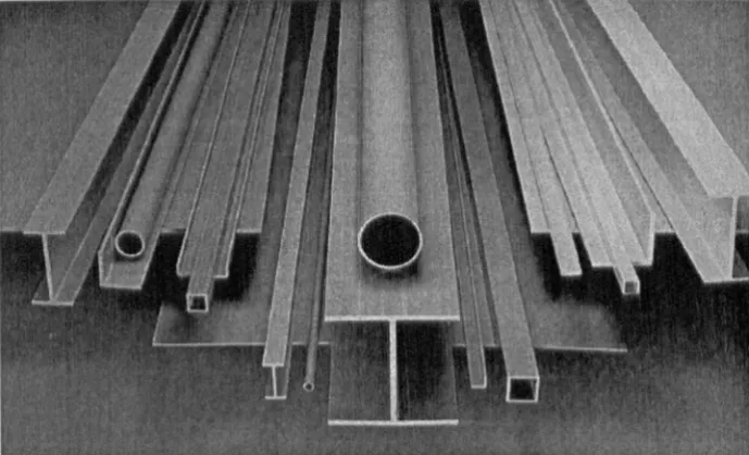
The pultrusion process can produce straight sections having most geometrical cross-sectional shapes at any desired length. The maximum cross-section of pul-truded profiles will continue to increase as the process reaches its maturity. The products can be solid or hollow, with variations in shape from bars and rods to complex custom sections. Most of these currently available standard products have steel like cross section shape. Figure 2.4 shows EXTREN pultruded shapes
Roving creels
Resin impregnator
Surfacing material
/ '
[image:38.497.95.440.379.588.2]Forming and curing die
Figure 2.3: Typical pultrllsion process used.
Cut-orr
saw
'C
aterptl.
lartype puller
2.4 FRP Pultruded Composite Profiles 11
Structural shapes consist of reinforcing materials, resin matrix, together with a surfacing mat to improve the composite surface appearance, chemical resistance and weather resistance, and a variety of ancillary materials such as pigments to impart
colour, accelerators to cure the laminating resin, internal release agents, inert fillers, etc. (Meyer, 1985). The reinforcing materials normally used are E type fibreglass continuous strand mats and continuous fibreglass rovings. The laminating resin
may be an unsaturated polyester resin, a vinyl ester resin, or an epoxy resin. The majority of all pultruded products currently use polyester resins due to its relatively
low cost.
Figure 2.5 shows an exploded view of one type of pultruded construction con-taining both continuous strand mat and roving reinforcements.
Continuous Strand
Mat
Continuous Strand Mat
Roving
Strand Mat
Surfacing
Figure 2.5: Exploded view of pultruded composite.
2.5
Properties and Design
As described in previous section, the properties of polymeric composites will depend on the type, the content, the form, and the arrangement of fibres and resin used. Typical polymeric composite properties given by Head (1996), for the three types of fibres continuously laid in the direction of stress, are listed in Table 2.1.
Table 2.1: Typical mechanical properties for GFRP, CFRP and AFRP (Head, 1996).
U ni-directional
Fibre Content Density Longitudinal Tensile Composite (%
by weight) (kg/m3) Tensile Modulus Strength
Material (G Pa) (M Pa)
Glass/polyester
50 - 80 1600 - 2000 20 - 55 400 - 1800 (GFRP)
Carbon/epoxy
65 - 75 1600 - 1900 120 - 250 1200 - 2250 (CFRP)
Aramid/ epoxy
60 - 70 1050 - 1250 40 - 125 100 - 1800 (AFRP)
The composite properties vary widely; this alone makes design work more
com-plex than for conventional material. In addition, the designer needs to consider the effect of loading duration, creep, fatigue resistance, environmental effects, temper-ature effects, moisture ingress and fire resistance. All of these will vary depending on the choice of fibre and resin configurations (Head, 1996).
This complexity, and associated high design cost, will discourage designers from using the composite material, such that a solution is to provide standard prod-ucts, like EXTREN structural shapes, with known material properties and
well-established design guidance.
Table 2.2 presents the minimum ultimate coupon properties of EXTREN
2.6 Applications 13
the perpendicular direction. The coupon properties of structural shapes show that pultruded composites are neither homogeneous nor isotropic; their mechanical prop-erties are directional and locally varying. Due to unidirectional fibre arrangement the material has higher strength acting axially along a profile. It is important to consider both longitudinal and transverse stress in design.
Table 2.2: Typical minimum ultimate coupon properties of EXTREN 525 senes pultruded shapes (MMFG, 1989).
Property Units Longitudinal Transverse
Tensile Strength MPa 207 48.3
Tensile modulus GPa 17.2 5.52
Compressive strength MPa 207 103
Compressive modulus GPa 17.2 6.89
Shear strength MPa 31.0
Shear modulus GPa 2.93
Flexural strength MPa 207 68.9
Flexural modulus GPa 11.0 5.52
Density kgJm3 1716 - 1938
The modulus of elasticity of EXTREN is approximately one-tenth that of steel. As a result, deflection is often a controlling design factor. In comparison with metal the shear modulus is low, and so shear deflection should often be considered in
design.
2.6
Applications
FRP's are suitable in all engineering areas, including aerospace, marine, automotive, sport, building and construction. On consulting the literature of the engineering
this growth is expected to continue, at pace, into the next century.
2.6.1
General Applications of Polymer Composites
In the aerospace industry, applications have been develop d in the construction of
rockets and satellite components, wing skins and small structural beams for aircraft,
and ev n the main rotor blades and rotor head on helicopters (Ballinger, 1990). U.S.
Air Force's B-2 stealth bomber aircraft (Figure 2.6), developed by Northrop in the
1980s', has a massive carbon fibre reinforced composite structure, including its large
win box, manufactured by LTV (Stonier, 1991). The INTELSAT-V, international
telecommunications satellites, ach have over 400 individual advanced composite
parts, developed in the United States, Europe and Japan (Stonier, 1991). All
com-posite voyager aircraft (Rutan) and business aircraft (Beechcraft) have flown ( har
-rier, 1990). It is reported that nearly 4 tons of composite material is used in the Airbus A340. This is also the first airliner to have a composite horizontal tailplane
which also acts as a fuel tank (Anon, 1992 a).
Figur 2.6: First B-2 aircraft during flight testing. (Courtesy .S.Air Force.)
2.6 Application 15
a contact moulding proc which i simple. Almost all boat hull up to 20 metre in
I ngth ar now built from hand la -up GRP (Leggatt 19 4). Th Royal avy has
built the 496 ton H.M . . Wilton ( igure 2.7) (Baili ,1991). It i al 0 reported that
10 m tr high FRP tower ar r et d as automated olar pow r d light tation in
wat rs urrounding th i land of he Phillipin ( non 1 a).
Figur 2.7: H. 1. . Wilton, a min hunt r who hull i virtually all glas fabri and poly ter r in.
or autom tiv pr du ion th application of composite r duce th numb r of
y t m co t. th ov rall w igh and th packag pa e. The u of
th mat rial has gro~ n on id rably in volum and ophi tica ion v r th pr vi u
20 ar ( harri r 1 0).
olym ri ompo it ar u d appr ciably in t rIng m chani m p w rtrain
III rior 1 m n
I uil by Ma ra utomobil
c. It is claimed that h Espa e ( igur 2. ),
i th only car in th world in whi h the body
ompl omp it mat rial . Th body parts w r made of
m Iding ompound ( ~I ) whi h do n t l' quir fur h r fini h. (Anon, 1 9
Figur 2.8: Composite French R nault Espace.
Composite material has not only been used in the body panels of vehicles, but
also been used in load component. The Ford's ontour concept car is featured with
a transvers ly-mounted composite leaf spring (Anon, 1992 b).
In civil ngineering, FRP has been extensively used for construction of tanks,
pipes and ducts for many years. Th se products ar often manufactur d by the
-filament winding or hand lay-up method. It is the predominant material in the
fi Id of small size domestic and industrial tank constru tion. Its mould-ability into
any free shape, light and strong, make it suitable for use as decorative panels of
building, walls, partitioning, etc. So far, in the building industry, the composites
have be n mainly used as large panel units, roof structure and small folded pIat
systems. Figure 2.9 shows four domes, up to 50 metres in diameter, covering a
2.6 Applications 17
Figure 2.9: GRP domes at Sharjah International Airport 1977 (Leggatt, 1984).
2.6.2
Structural Engineering Applications
Although FRP has been around for more than half century, it still represents a
new construction material category for the construction industry, and its
applica-tions in this field are still being established. For civil/structural applicatioll, both
the strength and stiffness of the material are critical. 'The strength and stiffness
prop rties of the pultrusion composite are not yet fully realized in practice and
many structural applications that would be possible are never considered. Howev r,
this market must soon be exploited because of the need for more energy efficient
structures' (Hollaway, 1993).
Advances of polymeric composite material give it a tendency to l' place
conven-tional materials such as steel, aluminium, and wood in a wide variety of structural
applications. However, to date, its application is usually limited to shuttering and
cladding, for building folded-plate systems. For various reasons, the introduction
into the construction industry of structural, load-supporting elements has been slow
(Abd-El-Naby and Hollaway, 1993; Leggatt, 1984). More recently, there have been
a number of prominent applications in structural engineering developed on the basis
Barbero, 1991).
Polymeric composite materials are particularly attractive where the contents or
the ambient condition are corrosive. FRP structures are employed in many segm nts
of the chemical process industries, including chemical, petrochemical and pulp-and
-paper plants, pollution-control and sewage-treatment facilities, and offshore oil and
gas production rigs (Liskey, 1985).
Pultruded walkways and ladders, fume scrubber structural elements, cable trays
and gutters are some of the items now found in corrosive environment (see
Fig-ure 2.10). FRP standard pultruded sections (wide-flange I-Beam, angle etc.) have
been used for hundreds of glass fibre-reinforced outdoor platforms installed at Dow
Chemical facilities where the pultruded platforms are exp cted to last 15-20 years,
[image:46.495.81.424.376.591.2]but wood and steel platforms fail in 3-5 years in such nvironm nts (Lass, 19 6).
Figure 2.10: Support structure and handrail of this platform surrounding chemical
storage tanks are EXTREN.
-2.6 Applications 19
bre platforms used in a corrosive chlorine operation provided for a petrochemical
[image:47.495.76.421.154.395.2]complex at a Saudi Arabian oil refinery.
Figure 2.11: Pultruded glass fibre EXTREN platform for a petrochemical complex.
Figure 2.12 shows that EXTREN fibreglass standard pultruded sections used
to support 1,000 lineal feet of 54 inch diameter FRP pipes at the M tro Wastewater Treatment in St. Paul, Minnesota, USA (Anon, 1996 b).
Composite materials offer the offshore industry significant savings in platform topside weight and in installation and maintenance cost. One of the largest offshore
applications of composites is over 30 tons of fire protection panels, manufactur d by
Vosper Thorneycroft, and supplied to Amerada Hess for the helideck and part of the accommodation area of the IvanhoeJRob Roy rig. A composite well bay platform, consisting largely of pultruded decking elements, was installed to replac a heavily
Figure 2.12: FRP supports for FRP pipes, image from MMFG Profile, 'all 1996.
Gulf of Mexico.
A handful of GRP bridges and other structures hav been successfully built
around the world within the last 15 years.
Some of the first applications of fibre-reinforced plastics in complete bridg struc
-tures were in China. A number of pedestrian bridges have been built. Th first
major bridge carrying full highway traffic was th Miyun Bridge (Figure 2.13)
completed in September 1982 in Miyun Beijing (Head, 1997). Figure 2.14 hows
a glass fibre reinforced plastic cable-stayed pedestrian bridg completed in hina in
1986 (Anon, 1994 a). Guanyinqiao pedestrian bridg in Chongqing was compl ted
in May of 1988. It has FRP deck girders suspended from reinforced concrete rigid
2.6 Applications 21
Figure 2.13: Miyun highway bridge in China 1982.
In America, a number of structures have b en fabricated with pultruded profiles.
The high-rise Sun Bank building in Orlando, Florida has four 35 ft. high by 35 ft.
square rooftop turrets to house radio antennae Figure 2.15. Thes electrically
invisible enclosures are made with 10x10x1/2 inch EXTREN wide flange beams
(standard sections) and fibreglass nuts and bolts from Morrison Moulded Fiber Glass
Company. The turrets are designed to withstand hurricane-force wind (Balling r,
1990).
Figur 2.15: Composit turret at top of the Sun Bank building in Orlando, Florida (Photo courtesy of MMFG)
North America's longest fibr glass pedestrian bridge (50 ft. span) made com
-pletely of composite materials, is built at Devil's Pool, Fairmount I ark,
Philadel-phia, PA (Figure 2.16). The FRP beams were manufactured by Creative
Pultru-sions Inc. and the bridge was designed by E.T Techtronics. According to the design
2.6 Applications 23
environmental design which r sulted in significant cost saving (Anon, 1993 a)'.
Figure 2.16: Fibreglass pedestrian bridge in Philadelphia 1993.
In the UK, Maunsell Structural Plastic Ltd. 2, UK is a key player in developing
advanced composite materials for structural ngineering. Their advanced
compos-ite construction system has been used to install motorway message sign gantries
(Figure 2.17) (Robbins, 1992).
The nine bridges on the new approach roads to the Second Severn rossmg,
opened to traffic on 5 June 1996, are the first in the world to f atur full advanc
composite bridge enclosures (Figure 2.18). The Maunsell's bridg enclosur s
pro-vide a cost-effective solution to long-term maintenanc , by r ducing the rat of
corrosion and minimising future cost. Th enclosure system improv d af ty for
maint nance staff and road users and provided a n w aesthetic form for bridge
structures which has already been widely praised. All the visible superstructure is
2Maunsell House, 160 Croydon Road, Beckenham, Kent BR3 4DE;
Figure 2.17: Glass fibre reinforced plastic motorway message sign gantries.
of advanced composite material.
Aberfeldy composite cable stayed bridge (Figure 2.19) 112 m long with a 63
m span, built by Maunsell and Dundee University, was completed in October 1992.
The bridge is stayed from two 18 m high 'A' shaped GRP pylons using Parafil
cables - Kevlar aramid fibres sheathed in a protective low density polyethyl ne coat
(Anon, 1995 b). The deck, pylons and handrails are made out of pultruded glass
fibr reinforced plastic. It is the world's first major bridge in advanced composite
materials and incorporates a number of innovations in structural syst ms, materials and methods of construction (Anon, 1993 b).
2.6 Applications 25
Figure 2.18: Advance composite bridge nclosures (Anon, 1997).
Figure 2.20: Bonds Mill lift bridge Gloucestershire, VK 1994.
full highway traffic loading (Anon, 1994 b).
Europe's first suspension bridge of entire pultrud d composite profiles, wh re the
only non-composite materials in the bridge are the st I bearings at the foundation
and the bolts holding together the bridge, was constructed by co-operation b tween
Rambo0ll, a Danish firm of consulting engineers, the authorities of Kolding ity,
and Fiberline Composite 3, A/S in Kolding, D nmark (Figure 2.21). Th bridge is
40 metre long and 3 metre wide and designed to carry a variety of vehicles, such as
bicycles, motorbikes and snow clearing vehicles w ighing up to 5 tons. The bridge
f atures 15 different types of pultruded profiles with a ratio of 60% glass fibr sand
40% resins used in the structure. It was opened to the public in June 1997.
2.7 Conclusions 27
Figure 2.21: Fiberline cable-stayed bridg , Denmark 1997.
The longest stress-ribbon footbridge (Figure 2.22) using Aramid fibr compos-ite cable, FiBRA, has b n constructed by Tobishima orporation at a golf course in Nagasaki Prefecture, Japan. The bridge is 73 m long with a cl ar span of 64 m, using six FiBRA cables in the bridge slab (Anon, 1996 c).
2.7
Conclusions
FRP composites have b en shown to be successful structural materials, and have
been incr asingly used in various forms of structural applications in the construction
Figure 2.22: Longest stress-ribbon footbridge in Japan 1996.
material choice for corrosive environment, and likely to be most cost eff dive. Th re
is now no doubt that advanced composites are becoming stablished as an important
structural material for use alongside the conventional materials of steel, concrete and
Limb r. Wide use of FRP structures in innovativ constru tion has been limited by
several factors, such as lack of design guidelines, material prop rties, and d sign
awar ness and high material cost (GangaRao & Barbero, 1991).
To address these and oth r problems, many ngineers are working to improve
our understanding. Many valuable research projects into the mat rial and its
appli-cations have been, and are being carried ouL Continuing research and d velopment
of a better understanding of the behaviour of structure over their life time will help
Chapter 3
Literature Review on
Connections in PolYlller
Composite Structures
3.1
Introduction
Problems associated with the buildability and durability of structures of conven-tional construction materials have led to a growing interest in new structural systems of polymeric composite materials (Mottram & Zheng, 1996 b). Due to the nature of
these materials and their range of material properties, there are more design factors to be considered than with conventional materials. This makes design more complex and expensive, thereby increasing the overall cost of a project. This complexity and associated higher design cost discourages designers. There is no doubt therefore
that the construction industry will need to settle on some standard products and construction systems if designers are to be encouraged to work with these materials in preference to alternative solutions (Head, 1996). Standard pultruded structural
shapes are one of these standard products. They have been successfully used in a number of applications such as the roof top turrets on the top of Sun Bank building in Orlando (Figure 2.15), and the platform shown in Figure 2.11.
FRP pultruded structural shapes have been available for more than two decades, yet the development of their application has been relatively slow. One of the reasons
for this situation is that structural engineers is still not familiar with this material and its structural elements and connections. The design practice with conventional structural materials relies heavily on approved and legally standing design codes. There is no such recognised design code currently available for building structures fabricated from fibre reinforced polymeric composite materials. The only
avail-able design guidance is from pultrusion manufactures, such as Morrison Molded Fiber Glass Co. (MMFG), Creative Pultrusions Inc. \ and Fiberline Composites. Recently, EUROCOMP project which finished in 1996, developed a design code EUROCOMP (Clarke, 1996) without legal standing.
As standard pultruded sections resemble their steel counterparts in appearance, steel-type connections are recommended by the manufactures' design guidance such as MMFG (1989). Since the pultruded structural shapes have unidirection fibre reinforcement along their length, the transverse and through-thickness strengths are much lower than the longitudinal. As a consequence, steel-type connections do
not perform satisfactorily. It is the aim of this thesis to study the beam-to-column connection for pultruded frame construction. A literature survey has been carried out on FRP composite connections and the related topics such as member and frame.
3.2 Study of Pultruded Members 31
3.2
Study of Pultruded Members
Commercially produced pultruded FRP structural shapes have been investigated extensively and research has involved: (1) the mechanical properties (Sims, et al., 1987; Bank, 1987, 1989 a, 1989 b, 1989 c; Mottram, 1991), (2) buckling of beams (Bank, et al., 1993, 1994 a), (3) Lateral-torsional buckling (Mottram, 1992; Brooks and Turvey, 1995), and (4) buckling of pultruded FRP column (Hewson, 1978; Barbero and Tomblin, 1992; Brown et al., 1998).
For design purposes both stiffness and strength properties of structural members are required. Due to the nature of pultruded material, the stiffness in longitudinal direction is generally higher than in transverse direction (see Table 2.2). Testing to determine the stiffness and the deflection of beams has demonstrated that they have relatively low stiffness, so that frame design will be governed by serviceability requirements. In addition, the transverse shear stiffness of FRP material is primar-ily derived from the relatively flexible plastic matrix material and the ratio of the longitudinal Young's modulus to shear modulus is higher than the 2.6 value com-mon for isotropic material; therefore, shear deformation effects which are usually
neglected in conventional structural analysis, cannot be neglected in the analysis of FRP structures (Bank, 1989 c).
To take account of shear deformation in the deflection of FRP beams Bank
(1991), considering anisotropic properties of pultruded FRP material, proposed a new material/structural stiffness property - beam section shear modulus (Gb) which is found from direct experiment on full-size pultruded FRP beam rather than on coupon tests. Proposed (Gb) will replace the term kG (k is shear coefficient and G is shear modulus for isotropic materials) in the isotropic formulation of shear