UPPER LIMB PROJECT
Modeling of the upper limb
Erik J.Dijkstra, BSc. s0142395
This report is submitted in fulfillment of the work placement required for the degree of Master of Science in Mechanical Engineering.
MSc. Biomechanical Engineering Department of Engineering Technology
University of Twente
October – December 2010
Abstract
The upper limb is used in many activities of daily living(ADL), think about feeding and
personal hygiene. Impairment can lead to inability or trouble in performing these ADL.
Problems with the upper limb can arise due to impairments to the neurological or
musculoskeletal system. The most common clinical condition where both systems are
involved is spasticity. However the pathophysiology of spasticity is not fully understood.
Current research is investigating the relationships between the impairment and human
functioning by measuring the patients in ADL. These measurements are used to build a
model of the upper limb, creating a way to further analyse and understand the
relationships between impairment and human functioning.
From a systematic literature review, on upper limb movement analysis during reach and
grasp movement, it became clear there are only a few studies done on upper limb
kinetics. An additional search provided more kinetic data and guidelines on how to
perform an upper limb movement analysis. These guidelines were used in a movement
analysis of an eating movement where an eight camera Vicon system was used to collect
kinematic data. The analysis protocol was kept in coherence with those found in
previous studies.
With the data from the literature review, a basic model of the upper extremity was build
to identify problems arising from modelling of the upper limb. The model build has
seven degrees of freedom, three at the shoulder, two at the elbow and two at the wrist.
Scapular movement was not taken in account due to its complexity. Every degree of
freedom is represented by a revolute joint and the coordinate systems in the joints are
described using the Denavit-Hartenberg convention. Matlab and Matlab Simulink were
used to build an inverse and forward dynamics model.
During the simulations, crucial elements in forward dynamics are found to be the initial
conditions, the time step, and the integration algorithm used. Also the order of the
revolute joints turned out to influence the behaviour of the model especially for shoulder
adduction movement. This is primarily related to the method for defining the coordinate
frames in the revolute joints. Multi joint movement showed instability when one of the
segments became an inverted pendulum.
When proceeding with modelling of the upper extremity, it is recommended to use a
different method for programming the model because of restrictions within Matlab
Simulink. A more thorough literature search on modelling should be performed to make
mature choices in the method and algorithms to use. A feedback loop should be
implemented in the forward dynamics to prevent unwanted behaviour.
Table of Contents
Preface...3
1 Introduction ...4
2 Anatomy of the upper limb ...5
2.1 Bone structure ...5
2.2 Joints ...6
3 Clinical condition ...7
3.1 What is spasticity...7
3.2 Pathophysiology of spasticity...7
3.3 Current assessment of spasticity ...8
3.4 Discussion ...8
4 Literature review ... 10
4.1 Search terms ... 10
4.2 Abstract screening ... 10
4.3 Full text selection ... 11
4.4 Data extraction ... 11
5 Upper limb movement analysis ... 14
5.1 Recording methods ... 14
5.2 Marker placement ... 14
5.3 Protocol for movement analysis ... 15
5.4 Vicon lab session ... 15
6 Modelling of the upper limb ... 16
6.1 The model ... 16
6.2 The InvArm function ... 18
6.3 Simulink SimMechanics ... 20
6.4 Hand calculation check ... 21
7 Results ... 23
7.1 Model behaviour... 23
7.2 Initial conditions ... 25
7.3 New results... 26
7.4 Sequence of revolute joints ... 28
7.5 Multi actuation ... 29
8 Discussion... 31
8.2 Discussion on the results ... 31
9 Future considerations ... 33
10 Reference list ... 34
I. Protocol ... 36
II. Matlab InvArm function ... 44
III. Simulink block scheme ... 47
IV. Model behaviour ... 48
Preface
A part of the master programme of Biomechanical Engineering at the University of Twente is an internship of at least ten weeks. This report describes the work I performed during my internship in the United Kingdom. It is part of a joint project between Keele University, at Keele, and ORLAU at Oswestry. ORLAU is a well respected research and development institute in Oswestry in England. The institute also offers clinical services for patients with mobility problems and provides education and training facilities for researchers and physiotherapists. Within Keele University I was stationed at the School of Health And Rehabilitation (SHAR), in the physiotherapy department, where I sat most of the days working on the project.
The main aim of the project was to create a basic model of the upper extremity to identify and address the problems arising from modelling. The first four weeks consisted of performing a literature review. For the remaining weeks I spend four days a week at Keele working on modelling of the upper limb. The other day of the week I had the privilege to take part in several clinics at ORLAU. Clinics ranged from clinical to pure technical clinics; Assessment of patient’s mobility with and without the use of a gait lab, and reviewing and discussing clinical results of gait analysis of patients, to the calibration of the force plates in the gait lab. These clinics have been very educational and gave a good impression of the work field of a Bio-engineer.
1
Introduction
Impairment can lead to disability and inability, or trouble, to perform activities of daily living (ADL). In order to help people improve their life when affected by impairment, there is the need of an understanding of the impairments and the impact they have on human functioning.
Measurements play in important role in understanding impairments as measurements quantify the parameters to describe the impairment. The measurements can be used to model the relationship between the impairment and human functioning, for example in ADL. Such a model will help get an understanding of the pathophysiology related to the impairment, comprehend the relationship and can be used to evaluate current rehabilitation methods used to treat the impairment.
The upper limb has a major contribution in the realization of ADL, think about feeding activities and activities of personal hygiene. Reduced ability to perform ADL where the upper limb has a crucial role therefore has a great impact on the quality of life. However, possibly due to the complexity of the upper limb, impairments of the upper limb have not been studied often. This is especially the case in neurological conditions where the failing of the neurological system (control component) leads to a failure of the skeletal system (mechanical component) which gradually worsens if the neural impairment is not resolved.
Within certain constraints the upper limb can be modelled. In this report a start is made on building a model of the upper limb to discover the challenging areas in modelling. Literature is reviewed to gain knowledge on analysis of upper limb function and a movement analysis was performed to collect data on upper limb movement during an activity of daily living. Although the work carried out is based on non-impaired subjects, the end aim is to apply the lessons learnt to develop solutions for people with disability.
This report can roughly be divided into five parts; introduction, literature, movement analysis, modelling, and evaluation.
i. Chapter two and three, including this introduction, make the first part of the report. The two chapters discuss the anatomy of the upper limb, and the clinical conditions that are the main drive behind this study.
ii. The literature review performed, describing a systematic approach to review literature is embedded in chapter four. Making it part two in the report.
iii. Chapter five, the third part, discusses the movement analysis that took place for this project and will elaborate on some important issues regarding analysis reliability and inter study coherence.
iv. The modelling is described in chapter six and seven. This comprises the model that is created for the purpose of analysing upper limb movements and dynamic behaviour, and the results from the forward model for different situations.
2
Anatomy of the upper limb
This chapter gives an overview of the anatomy of the upper limb relevant for the purpose of this study. First the bone structures are described followed by the joints that form the connection between the bone structures.
2.1 Bone structure
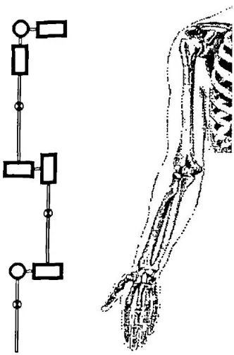
The bones relevant in upper limb movement can be divided into four groups; the pectoral girdle, the upper arm, the forearm and the hand. Each of these groups and their bones will be discussed in respectively the same order. Figure 1 shows the bones in the upper extremity.
2.1.1 The pectoral girdle
The pectoral girdle consists of the clavicle anteriorly and the scapula posteriorly. It connects the upper limb to the axial skeleton and provides attachment sites for many of the muscles that control the movement of the arm.
The clavicle lies almost horizontally at the root of the neck and can easily be seen and/or palpated through the skin throughout its whole extent. Its most important functions are: to act as a brace to hold the scapula and
arm laterally of the thorax, enabling the limb to swing clear of the trunk; and to transmit a part of the weight of the limb to the axial skeleton, in this way diminishing the muscular effort required for that purpose.
The scapula is a large, flattened, triangular bone. It lies on the posterolateral aspect of the chest wall, covering parts of the second to the seventh ribs.[2] Each scapula has three borders. The superior border is the shortest and sharpest border. The medial border lies parallel to the vertebral column. The thick lateral border abuts the armpit and ends superiorly in the glenoid cavity. This cavity articulates with the humerus, forming the shoulder joint.[3] The posterior surface of the scapula shows a prominent spine, easily felt through the skin, ending laterally in an enlarged, roughened triangular projection called the acromion. The acromion articulates with the clavicle, forming the acromioclavicular joint.
2.1.2 The upper arm
The humerus is the longest and largest bone of the upper limb. The proximal end consists of the head and the greater and lesser tubercles. The hemispherical head fits into the glenoid cavity and the tubercles are sites of attachment of the rotator cuff muscles. Immediately inferior to the head is the anatomical neck. The distal end of the humerus is expanded transversely and forms part of the elbow joint with the trochlea and capitulum. Anatomical landmarks are the medial and lateral epicondile.
2.1.3 The forearm
The radius is one of the two bones in the forearm and lies on the lateral side. Upper and lower sides are both expanded. The proximal end consists of the head which is disk shaped and its surface is hollowed out to form a shallow cup for articulation with the capitulum of the humerus. The distal end is the widest part of the radius. Its lateral surface is slightly rough and projects downwards beyond the
rest of the bone to form the styloid process. This projection can be felt through the skin when the tendons concealing it are relaxed.
The ulna is the medial bone of the forearm and is parallel with the radius when the arm is in supine. The proximal end is thick, and hook like, the concavity of the hook directed forwards. The bone diminishes in size from its upper to its lower end, which bears a small, rounded enlargement termed the head of the ulna. At the proximal end of the ulna displays two substantial processes, the olecranon and coronoid, and two articular areas, termed the trochlear and radial notches. The trochlear notch articulates with the humerus and the radial notch with the radius. The distal end is slightly expanded and comprises the rounded head and the styloid process.
2.1.4 The hand
The carpus are the eight short bones in the wrist, which are arranged in a proximal and a distal row, each containing four bones.
2.2 Joints
The three joints that will be discussed are the glenohumeral joint, the elbow, and wrist joint. The glenohumeral joint, also known as shoulder joint, is formed by the humeral head and the glenoid cavity of the scapula. In general it has three rotational degrees of freedom, flexion and extension, ab- and adduction, and in- and external rotation. The ligaments and muscles keep the humeral head in place ideally constraining translational movement. A mechanical representation of this joint is a ball and socket joint as can be seen in Figure 2.
Figure 2: Shoulder joint Figure 3: Elbow joint
The elbow joint can be regarded as a hinge joint, see
Figure 3
, allowing flexion and extension in the elbow. The movement freedom in all other directions can be neglected as they are suppressed by ligaments, muscles and the bony structures.Slightly more distal from the elbow joint, a second degree of freedom, pronation and supination of the forearm originates. A mechanical equivalent for this type of joint is a pivot joint, shown in
Figure 4
.Finally wrist flexion and extension and wrist deviation are both occurring at the distal end of the forearm, where ulna and radius are articulating with the carpal bones.
3
Clinical condition
Upper limb problems can arise due to impairments in the musculoskeletal system, or the neurological system. There are however clinical conditions where both systems are affected. The most common clinical condition where both systems are involved is spasticity. Spasticity is an impairment arising from a problem in the neurological system. This can lead to problems interfering with the performance of the musculoskeletal system, and in certain cases lead to changes in the biomechanical properties of the mechanical system. This chapter will elaborate further on what spasticity is, its pathophysiology, and current methods of assessing spasticity.
3.1 What is spasticity
Spasticity is a motor disorder associated with upper motor neurone lesions. [4] The disorders in which spasticity is a common finding are [5];
Multiple sclerosis (MS); A disorder where the myelin sheets around the nerves are affected, resulting in poor transmission of signals through the nerves.
Stroke; Ischemic or hemorrhagic stroke can cause severe damage to the area of the brain affected. Either caused by a short on oxygen and nutrients in the brain cells or toxicity due to rupture of a blood vessel. [6]
Cerebral palsy (CP); The term cerebral palsy may refer to any one of a number of neurological disorders that appear in infancy or early childhood. It permanently affects body movement and muscle coordination but is not progressive. In some cases of cerebral palsy, the cerebral motor cortex hasn’t developed normally during fetal growth. In others, the damage is a result of injury to the brain either before, during, or after birth. [7]
Spinal cord injury (SCI); damage to the spinal cord can occur due to a traumatic blow to the spinal column or other disorders, like MS or stroke. It can be classified as complete or incomplete depending on the ability of the spinal cord to convey messages from and to the brain. [8]
Head injuries; Refers to trauma to the head. This may or may not include damage to the brain. Traumatic brain injury belongs to this group. Common causes are traffic and domestic accidents, falls, and assaults.
3.1.1 Definition
There are many different definitions for spasticity, but the most accepted seems to be Lance's definition. [4]
Spasticity is a motor disorder that is characterised by a velocity dependent increase in the tonic stretch reflex with exaggerated tendon reflexes, resulting from the hyper-excitability of
the stretch reflex, as one component of the upper motor neurone syndrome.
More recently, the definition of Lance was found to narrow, it is suggested it should be widened to;
Disordered sensori-motor control, resulting from an upper motor neuron lesion, presenting as intermittent or sustained involuntary activation of muscles.
The widened definition seems to be more in line with the current understanding of pathophysiology and clinical practice.[9]
3.2 Pathophysiology of spasticity
clear that spasticity is not always considered to be a problem. Spasticity is only considered a problem as it interferes with the ability to perform a task. If spasticity does not affect the individual’s ability to perform tasks, it is often not treated.
The mechanisms proposed to explain spasticity all involve the neurological system. The neurological system is the controller component of the human. It can be described in more engineering terms as a structure containing many positive, but also negative, feedback loops. Muscle spindles, Golgi tendon organs, and other sensors are the organelles providing the feedback to the controller.[3] Most of the feedback is positive feedback however there are also negative feedback loops like the negative feedback of the 1b afferents from the Golgi tendon organs. Other controller input are the signals originating from the different spinal tracts.[10]
An important mechanism involved in spasticity is the inhibitory synaptic input. In mechanical systems one can turn of certain actuator signals. However this is not possible in the human system, where active negative activation of the inhibitory nerves is needed to inhibit the actuator signals. The inhibitory pathways can therefore be considered as negative feedback loops, having the ability to reduce the signal input to the muscles.[10] Some neurological injuries turn of these inhibitory pathways. The loss of this active inhibition is the most probable reason for seeing the signs of spasticity.
3.3 Current assessment of spasticity
Different methods can be used to measure spasticity. Malhotra et al.[9] investigated the different measurement methods in literature and the methods found can roughly be divided in three groups; EMG, biomechanical, and scales. Surface EMG can be used to quantify the muscle response to stretch by using the H-reflex or F-reflex response. Biomechanical measures often use stiffness during a controlled motorized perturbation as an indirect measure of spasticity. However the most applied assessment method in clinical practice will be the use of scales. Tardieu scale, Ashworth scale, and Modified Ashworth scale are just a few examples. The scales do not require any appliances and can be performed by the physiotherapist alone. The physiotherapist moves the limb through its range of motion at different velocities, sensing for resistance and the occurrence of a 'catch' during movement.
3.4 Discussion
With the pathophysiology of spasticity not fully understood, it is difficult to give an unambiguous definition. Therefore measurements are used to get a better understanding of the impairment. The use of biomechanical and EMG methods in measuring spasticity both involve expensive equipment and need specialists to operate the systems. It is therefore less applied in clinical practice and currently most used in research settings.
The scales that are widely used in clinical practice have one major drawback. The measurement is performed by a human and therefore unreliable. Many parameters like temperature, cooperation of the patient, state of muscles of the physiotherapist performing the measurement, will influence the
accuracy with which the physiotherapist can determine the resistance in a limb. The results from a patient assessed by two physiotherapists, both performing the same test, may not be the same. But the most inaccurate measure will be the detection of the catch and relating it to a certain angular position, as used in the Tardieu Scale. When the catch happens the sensory information has to travel to the brain before the physiotherapist actually senses it and in that time the limb has been moved further and thus the angle associated with the catch is overestimated.
4
Literature review
There are several stages in a literature review. First the search terms are determined, based on the information needed. Next a search is performed with these search terms in the appropriate, depending on subject, search engines. An example is the use of PubMed for medical journals. The resulting articles will then be screened on whether they will provide the information necessary, by reading the abstracts. Next step is to find the full text of the articles left, and read them. Even though some articles my look promising from the abstract, it does not always correlate with what the full text compromises. In the end a selection of articles has been found useful and data can be extracted and used in the research project.
The literature review described in this chapter does not start at the first stage. The search of the articles, matching the search terms, has been performed by associates. The process starts at the screening of the abstracts. Nevertheless, the following paragraphs will give a description of all the steps in the literature review for this project
4.1 Search terms
As mentioned above, the first stages of literature research are performed by associates. However to get an overview of the process, a short summary will be given on the search process.
When defining the search terms it is important to look at the information required for the research. For the project it was to find out what is known in the area of upper limb kinematics and kinetics. In general three groups of search terms are used. Search terms related to the structure in this case the upper extremity. Terms linked to what has been measured and terms involving the movements performed.
Structure; upper extremity, upper limb, wrist, elbow, shoulder, finger, arm, hand, muscle Movement; grip, grasp, reach
Measurement; kinematic, displacement, velocity, acceleration, movement, kinetic, torque, moment, force,
All the search terms are used in different combinations with operator terms like AND and OR to retrieve the best results. The search terms can be used as title words or general search terms. The search has been performed in the MEDLINE database. Also several medical headlines are used to refine the search. After deleting the inappropriate titles and duplicates, this resulted in a selection of three hundred articles to be screened.
4.2 Abstract screening
With the articles resulting from the search the next stage in the process can begin. For the current study, the abstracts are screened using several criteria. Each of them is mentioned with a short explanation.
English language: The article should be writing in English. Peer reviewed: Has the article been checked on validity?
Subject age >=18: Are the subjects used in experiments 18 years or older? Human subject: Is the subject used human?
Experiment/review: Does the article compromises an experiment or a review?
Reach to grasp, grip or point: Does the article describe any of the mentioned movements? Shoulder and elbow movement: Is shoulder and elbow movement investigated?
Excluding trunk compensation: Is the trunk movement restrained or compensated for?
Exo-skeletally unconstrained movement: Are the movements made natural movements without external constraints?
Measurement of timing kinematics/kinetics: Are there measurements taken regarding timing, kinematics and/or kinetics? Think of trajectories, moments/forces, and joint angles.
For each of these criteria a point could be rewarded if the question is answered positively. The total sum of points gave an idea of the relevance of the article concerned for this research. Articles with ten or eleven points are most likely to be relevant however can be placed in a different group. For instance if there are no healthy or human subjects, the article will be rejected, even if it scores on all other criteria.
Out of the three hundred article abstracts, 112 seemed relevant, 50 were to be considered, and the remaining 138 articles could be rejected.
4.3 Full text selection
Normally, before starting a full text selection process, if there are that many relevant articles remaining after an abstract screening, a discussion will take place between the reviewers. The outcome of such a discussion might result in a reduced number of relevant articles, reducing the workload. In this case this discussion has not taken place. Therefore all 112 articles were listed for a full text review.
With this many articles it is wise to selectively read certain sections of the articles. Most articles use a general format where first an introduction is given. After the introduction methods are discussed, giving information about the participants used in an experiment, experimental set-up, and methods used for data analysis. After the description of the methods often the results will be presented, either in words or in graphs to end with a discussion and a conclusion.
In search for useful data on kinetics and kinematics of the shoulder and elbow joint during reach to grasp movements, the following approach was taken; At first instance only the methods and results paragraphs were read. If these had interesting content, the article was read as a whole. Articles not using the structured format were read entirely.
This stage of the literature review process resulted in only three useful articles. Many articles did describe the timing aspects of the movements but when it came to kinetic, joint angle or trajectory data only wrist or fingers were reported.
4.4 Data extraction
The final stage in a literature review is the data extraction. The data in the final selection of articles will be collected and processed for the purpose of the study.
For this project the data of interest is any data on the kinematics and dynamics of the shoulder and the elbow during reach movements or activities of daily living. Besides that it is useful to know how many healthy subjects are represented in the data and what type of measuring method is used.
strategies. The C6 patient compensated a task change primarily in the elbow compared to the all joint recruitment in the control subject.
Gréa et al.[12] observed nine subjects performing a grasp movement to a cylinder that was perturbed. Results show the final arm position and wrist trajectory showing that final posture is planned in advance and used as control variable in the central nervous system.
Marotta et al.[13] performed two experiments. 14 subjects were to reach to a block of which the orientation could be perturbed. The results comprise three dimensional trajectories of the arm and torsion of the upper arm as function of the lower arm torsion with respect to the upper arm. Data show that a linear relation exists between upper and lower arm torsion, making the components of the arm rotate in coordination with one another. Arm rotation only accommodated for about half of the re-orientation required to align grasp with the block. The formation of hand and fingers must therefore account for a large portion of the required torsional rotation. These observations show that the entire arm-hand system contributes to grasp orientation.
4.4.1 Additional articles
The three articles found through the literature search did not provide all the data required, therefore another simple search of a known author is performed to get additional articles.
The author used for the search is Murray as he is known to have worked in the area of upper limb kinetics. An article written by Murray and Johnson[14] is used to find more articles. They performed a study on the external forces and moments at the shoulder and elbow while subjects performed everyday tasks. From this article four additional studies, retrieved from the reference list, found to provide useful information.
Murray and Johnson[14] studied ten subjects to establish a database of upper limb kinematics and kinetics. Data on ranges of motion and external forces and moments were collected. Greatest range of motion (111.9º) and maximum moment (14.3 Nm) at the shoulder occurred during reach and lift tasks. For elbow flexion reaching the back produced the greatest elbow flexion (164.8 º) but greatest elbow flexion moment (5.8 Nm) occurred in a lifting task.
Kontaxis et al.[15] proposed a framework for the definition of standardized protocols for measuring upper limb kinematics. Summarizing essential steps in a motion analysis protocol, basic recommendations are formulated and problems identified.
Buckley et al.[16] gave a review of the current knowledge on dynamics of the upper limb during ADL. Discussing the few published results on upper limb kinematics, they found differences in methods and joint axes definitions. These differences make it difficult to compare the results. It is also noticed there is a lack of data on limb segment orientations, velocities and accelerations. Available results suggest that current rehabilitation manipulators and orthoses move at far lower speeds than the healthy human arm.
Morrey et al.[17] studied thirty-three subjects on elbow movement during fifteen ADL. Functional arc of motion of elbow flexion was found to be 100 degrees, 30 to 130 degrees. Tests could be accomplished with 50 degrees of pronation and 55 degrees of supination. Rotation of the forearm is difficult to measure clinically as the zero position can only be approximated and carpus rotation cannot be excluded.
graphs. Slope, to represent the relative magnitude of changes in the joint angles used, and movement area quotient to say something about the timing difference between the relative motion of the two joint variables.
Besides these additional five articles, another source of information was the thesis submitted by Murray in 1999, to obtain his PhD degree[19]. This thesis reported on the determination of upper limb kinematics and dynamics during everyday tasks, providing information regarding length, mass, and inertia properties of the segments of the upper limb. Apart from the body parameters, a model of the upper limb was made using the robotics toolbox [20]in Matlab.
4.5 Discussion
The search result showed a lot of articles concerning the hand and finger kinematics without
mentioning the elbow and shoulder. Since shoulder and elbow joint kinematics and kinetics is the area of interest most articles did not came through the screening and an additional search was needed.
The majority of the relevant studies found, give information on the kinematics of the upper limb during ADL. Joint movement is given in mean angles, maximum angles or angular range of motion. Due to the difference in the experimental protocols used it is difficult to compare these quantitative measurements. Essential issues to take in account for comparison are therefore coordinate systems and zero definitions. This emphasises the importance of the coordinate frames and also the protocols to use when building a model or doing movement analyses.
The literature search provided useful information, if not useful now it will be applicable when the modelling has reached a more mature state. Joint co-ordination and muscle activities for example can be used when a muscle model is implemented. However when keeping in mind the goal of building a basic model of the upper limb, some essential issues have not been elaborated in the articles. The studies encountered till now all deal with the kinematics of the upper limb, some also using inverse dynamics methods to derive the forces and moments acting on the limb segments.
5
Upper limb movement analysis
For long the motion of the upper limb has been observed and admired, but a systematic study requires the application of appropriate measurement techniques.[18] Recent developments in the area of information technology enabled most laboratories to have access to sophisticated motion analysis equipment.[16] This chapter comprises an overview of the recording methods used in the literature and will discuss several important issues with respect to the marker recording methods. Also the standardization of protocols for measuring upper extremity kinematics will be highlighted while describing a protocol for the kinematics data collection performed.
5.1 Recording methods
For a movement analysis, different systems can be used. Morrey et al.[17] used goniometers, where an orthosis is equipped with goniometers to measure the joint angles. Although the accuracy of such a system is sufficient, it can be said that the use of an orthosis limits the subject to make a natural
movement. Therefore more emphasis is placed on video based systems for the tracking of movements.
Mainly two different forms of video tracking are regularly encountered in literature. Systems like OPTOTRAK used by Marotta et al.[13], and SELSPOT used in research conducted by Gréa et al.[12], use infra-red emitting diodes placed on the subject. An infra-red sensitive camera system detects the diodes and records their movement. These systems are similar to a Vicon system, where the markers placed on the subject are small spheres covered in reflective material. This difference also shows the disadvantage of the IRED systems compared to a reflective marker system. The power supply necessary for the IRED's requires power cables to be attached along the body of the subject, inflicting with the wish to analyse in a situation as natural as possible.
Even though Vicon is the most well known system using reflective markers there are also other software packages that can be used with reflective markers. Murray and Johnson used APAS software to process the data collected of tasks associated with daily living using four video cameras.[14] However there are also many researchers writing their own programme to process the captured data from the cameras.
5.2 Marker placement
With regard to marker placement certain aspects should be kept in mind. The positioning of the markers and the positioning of the subject to be analysed are crucial. On each body segment, at least three markers must be visible at all times to define its position and orientation.[14] The accuracy of the measurements will be influenced by marker movement relative to both underlying skeleton and other markers.
As the placement of the markers is important for the cameras to be able to spot the spheres, it is also crucial as the marker positions are used to build the model within the software. A misplaced marker can result in a biased joint angle and, if not noticed, cause a wrong interpretation of the results.
5.3 Protocol for movement analysis
In order to be able to compare the results from different studies it is required that the protocols used have no conceptual or practical difference. Kontaxis et al.[15] proposed a framework to standardize protocols for measuring upper extremity kinematics. This framework has been used as a guideline for the movement analysis performed in this study. The protocol used in the movement analysis can be found in appendix I. A short summary of the Vicon lab session is given below.
5.4 Vicon lab session
A kinematic data collection of an upper limb movement was conducted in order to get acquainted with movement recording with the use of a Vicon system.
5.4.1 Method
The movement recording took place in the Vicon lab of Keele University. Kinematic data was collected using an eight camera Vicon system. Data was collecting at a frequency of 100 Hz. The movement recorded was an eating movement where the subject brought the hand to the mouth and back again to the initial position. The collected data was processed off-line using the Vicon software.
Participants; For this movement analysis experiment only one subject was recruited, in the shape of the researcher himself. The subject has no history of impairment to the upper limb.
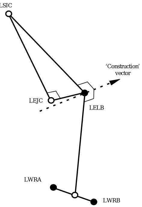
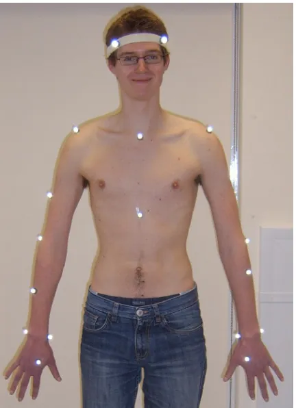
For marker positioning Vicon documents on Plug in Gait Marker placement were used.[21] The marker positions on the subject can be seen in
Figure 5
. A more detailed description of themarker positioning, movement made, and data processing can be read in the protocol in appendix I.
5.4.2 Results
[image:17.595.302.518.168.466.2]From the data collected during the eating movement, angular positions in the joints have been derived. The Vicon software could also provide the angular velocity and acceleration. The kinetics of the movement could not be calculated by the Vicon software, as there was no kinetic data collected.
6
Modelling of the upper limb
This chapter discusses the modelling of the upper limb. First the different segments and their interrelation are described with the use of Denavit-Hartenberg parameters. Next the kinetic and kinematic equations are written for the recursive Newton-Euler algorithm. To check the model it has been verified with a hand calculation. Finally the implementation of the inverse and forward model in Simulink is presented.
6.1 The model
The human arm model can be represented by a kinematic chain model. A kinematic chain model describes the relative positions between links of the arm and gives the axis of rotation for all the joints. Murray[19] used a kinematic chain model to evaluate the data from a movement analysis. This modelling approach has also been taken by Naaij[22] who studied the working space representation of the human arm. The arm model created in this study is based on the work of Murray.[19]
The model has seven degrees of freedom, corresponding to the seven axes of rotation. Three axes of rotation in the shoulder for flexion and extension, abduction and adduction, and internal and external rotation of the upper arm. Two axes of rotation in the elbow, one for flexion and extension and one for pronation and supination of the forearm. Another two axes at the wrist to accommodate flexion, extension and radial/ulnar deviation of the hand. A graphical representation of the model can be seen in Figure 6. The coordinate frames at each of the joints are defined using the Denavit-Hartenberg convention. An example of the use of the D-H convention is given in the next paragraph.
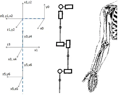
[image:18.595.76.475.399.717.2]6.1.1 Denavit-Hartenberg convention
The Denavit-Hartenberg convention is often used for selecting reference frames in robotic applications. Since the human arm can be compared to a robotic arm, this convention is also widely used in biomechanical studies. With two rotation and two translation parameters the minimal representation of one frame to another is obtained. Four parameters, from now on referred to as D-H parameters, are the parameters which describe the relation between two consecutive coordinate frames.
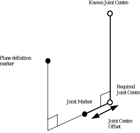
To get an idea of how this convention works an example is taken to explain the selection of the frames and the four parameters. The structure to explain the D-H convention can be seen.[1]
For the first joint, define the z-axis along the axis of rotation, or along the axis of translation in case of a prismatic joint. The x-axis of the base frame can be chosen freely after which the y-axis follows from the right hand rule to complete the coordinate frame. For the next joint again the z-axis is along the axis of rotation of the revolute joint. The x-axis is along the common normal of both z-axes, also the shortest distance between the two, and therefore the origin does not have to be in the centre of the joint. The D-H parameters only concern the motion of the links and not the physical placement of components.
The parameter is the depth along the previous joint’s z-axis from the origin to the common normal. Angle rotates about the previous z-axis
from the previous x to the new x-axis. is the length of the common normal itself. Originally this parameter is named but since there is an to confuse it with is chosen since it is also the radius of rotation about the previous z-axis. The fourth parameter, , is the angle about the new x-axis from the previous z-axis to the current z-axis. By using this convention only four parameters are necessary to describe a frame with respect to its previous frame. [1]
6.1.2 Parameters
All the joints in the model are connected to each other with bodies, also described as links. As can be seen in the technical representation of the arm in Figure 6, three of the links have a mass. These three links represent the segments of the upper limb. Starting from the shoulder; upper arm, forearm and hand respectively.
[image:19.595.313.508.221.435.2]In case of a robot it would be easy to determine the segment properties as you can disassemble the robot to measure every segment separately. The properties of the segments of the human upper limb on the other hand are not that easily obtained. Because the properties of the segments of the upper limb are different for every individual and the measurements impossible or cumbersome to perform on living subjects, it is necessary to estimate the parameters. Murray also addressed this problem and stated that for the modelling of the human upper arm for a quantitative biomechanical analysis, it is necessary to estimate certain characteristics of the body segments considered.[19] Body segment characteristics are the dimensions of the bodies, its masses, centre of masses and their moments of inertia.
The segment parameters used in the model of Murray[19] are also applied for this model. With the segment lengths known the D-H parameters could be determined. An overview of all the parameters, used to describe the upper limb model, is presented in Table 1.
D-H parameters Centre of mass locations
Moments of inertia
M
Link 0
0 -lc 0 0 0 0 0 0 0 0 0
Link
1 +2
0 0
2
0 0 0 0 0 0 0
Link
2 +2
0 0
2
0 0 0 0 0 0 0
Link
3 +2
-lua 0
2
Mua 0 0 -cmua T A L
Link 4
0 0 −
2
0 0 0 0 0 0 0
Link 5
-lfa 0
2
Mfa 0 0 -cmfa A T L
Link
6 +2
0 0
2
0 0 0 0 0 0 0
Link 7
0 -lh
2
Mh cmh 0 0 L A T
Table 1: Model parameters
With:
- Lc, the length of the clavicle, the distance from sternum to the shoulder.
- Lua, the length of the upper arm.
- Lfa, the length of the forearm.
- Lh, the length of the hand.
- Mua, the mass of the upper arm.
- Mfa, the mass of the forearm
- Mh, the mass of the hand
- Cmua, the centre of mass location of the upper arm along the longitudinal axis.
- Cmfa, the centre of mass location of the forearm along the longitudinal axis.
- Cmh, the centre of mass location of the hand along the longitudinal axis.
- L, A and T stand for longitudinal, anteroposterior and transverse respectively. Determining which radius of gyration to use in the calculation of the moment of inertia.
- , the angle of the revolute joint.
With the kinematic chain model and the dynamic parameters an inverse dynamics model can be constructed. An inverse dynamics arm model allows the calculation of the torques/moments necessary at the joints to produce a certain movement given the accelerations and all other parameter values each instant of time.
6.2 The InvArm function
described a mathematical model to model the movement of a robot manipulator and used it to simulate and control a real robotic arm. The inverse dynamics model comprises five steps. These five mathematical steps with their equations are given in the next paragraph.
6.2.1 Kinematics
The first step is the calculation of the velocities and accelerations of each link. For each link there are two forms of velocities and accelerations considered, linear and angular. This gives four equations, see eq. (1) to (4), which can be solved iteratively from link one to link eight to find the angular and linear accelerations and velocities of each of the links of the arm. Here is the rotation matrix from link
+ 1 to link . The base link only has linear acceleration equal to the gravitational acceleration in the direction of gravity. The angular acceleration and both forms of velocities of the base link are assumed to be zero.
= + ̇ (1)
̇ = ̇ + ̈ + × ̇ (2)
= × + (3)
̇ = ̇ × + × ( × ) + ̇ (4)
The second step is the calculation of the linear acceleration of the centre of mass for each link. This equation is similar to the linear acceleration of the links but then with the vector pointing to the centre of mass from the link’s origin instead of the vector which is the vector pointing from the link i-1 to the link I coordinate system.
̇ = ̇ × + × ( × ) + ̇ (5)
With these equations the kinematic characteristics of the upper arm are described. In order to calculate the kinetics of the arm the additional three steps should be performed.
6.2.2 Kinetics
The calculation of the net forces and moments is the third step in the process of building the model. Since the accelerations of the centres of mass are known from the previous equations, Newton’s law and its analog to rotational dynamics can be used to compute the net forces and moments acting on the centre of mass of each link.
= ̇ + × ( ) (7)
The angular analog is a form of Euler’s equation of motion for a rigid body. With , the moment of inertia around the link centre of mass.
The fourth step is the calculation of the local forces and moments acting on each link. As each link is connected to two other links, except for base and hand, forces from the two links are exerted on that link. The net force on the link is the sum of these two forces. The local moment of each link has four components. Two moments are from the interaction with the adjacent links like with the force. The moment caused by the local force acting on the link at a distance away from the origin. And last the moment caused by the net force acting on the centre of mass of the link.
= + (8)
= + × + × + (9)
These four equations, equation (6) to (9), can again be solved iteratively, this time from the most distal link to the base link. After solving the kinematics and the net and local forces and moments the final step can be performed. This final step is the computing of the torques required for a joint to compensate for the local moment and friction.
= ∙ + ̇ (10)
The above mentioned equations are implemented in a Matlab function that evaluates the equations one through ten. This function produces the torques given the angular position, velocity and accelerations of each link. The Matlab code of the InvArm function can be found in Appendix II.
6.3 Simulink SimMechanics
Figure 8: Simulink block scheme
The relation between the coordinate systems can be described using different conventions. The Euler-angle convention is used as it is the most straightforward in producing the same coordinate systems used in the InvArm function. Other options would be the use of quaternions where there is a rotation about a defined vector, or a 3x3 orthogonal rotation matrix. The full block scheme can be found in Appendix III. Both the programmed and the SimMechanics model are checked with a hand calculation as discussed in the next section.
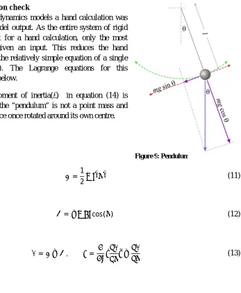
6.4 Hand calculation check
To check the inverse dynamics models a hand calculation was made to verify the model output. As the entire system of rigid bodies is too complex for a hand calculation, only the most distal segment was given an input. This reduces the hand calculation to solving the relatively simple equation of a single pendulum (Figure 9). The Lagrange equations for this calculation are shown below.
The term with the moment of inertia( ) in equation (14) is added as the mass of the “pendulum” is not a point mass and therefore gives resistance once rotated around its own centre.
=1
2 ̇ (11)
=− cos( ) (12)
= − , = ̇ − (13)
= ̈+ ̈+ sin( ) (14)
The models have been tested in two situations; purely static postures and dynamic situations with different angles. The static situations all gave the same results, thus no difference between hand calculation and model output. The results for the dynamic situation can be seen in Table 2.
̈ Hand calculation InvArm function SimMechanics
0.0124 −0.0127 0.0082
/ 0.2507 0.2255 0.2465
/ 0.3493 0.3242 0.3452
0.0124 −0.0127 0.0082
3000 /180 0.2065 −0.2122 0.1371
/ 3000 /180 0.4448 0.0261 0.3753
/ 3000 /180 0.5435 0.1247 0.4740
Table 2: Comparing hand calculation and InvArm function and SimMechanics model for different dynamic situations
From these results we can conclude that the models deviates from the hand calculated values. The reason for the sign difference in the InvArm function, for the situations where position is vertical, is not found. Besides this peculiar behaviour it can be noticed that an increased angular acceleration increases the difference between the hand calculation and the InvArm function. The SimMechanics model gives results closer to the hand calculated values for the angles /4 and /2. Because the SimMechanics model seems to produce better results, the inverse model in Simulink will be used to compute the torques.
6.4.1 Forward model
7
Results
In this chapter the results from the upper limb model are discussed. The results are presented in roughly chronological order. First the behaviour of the forward model is explained based on model input and output. However due to a mistake, the initial conditions were not set. The importance of initial conditions is mentioned and new results are produced and discussed. Next it is investigated whether the sequence of the joints influence the behaviour of the model. Finally multi joint actuation is analysed.
7.1 Model behaviour
The inverse model has been used to create an input for the forward model. The inverse model has been checked, as described in the previous chapter, and can therefore be used in the analysis of the forward model. A sine function has been used as input for the angular position of one joint at the time. The sine function was differentiated twice to provide for the angular velocity and acceleration. The input sine function is presented in Figure 10.
Figure 10: Angular input function
Figure 11: Forward model input torque profiles
Figure 12: Forward model output angular positions
As can be seen in Figure 11, the torques profile for shoulder flexion has the same shape as the sine function. This can be explained by the fact that the moment arm of the moment around the shoulder is the distance from the shoulder joint centre to the combined centre of mass multiplied by the sine of the flexion angle.
The angular position resulting from the forward simulation however shows some differences with the original input function. First thing to notice is the delayed start of movement. This delay is crucial as it can be reasoned that the other differences are a direct consequence of this delay.
lower than the moment fed to the system. The elbow and wrist torques are not computed with this increased shoulder flexion acceleration and therefore go into extension.
In the period where the shoulder is flexing, the acceleration grows a little more as the extended elbow and wrist reduce the moment arm of the combined centre of mass. This increased acceleration results in a larger maximum flexion angle occurring at the shoulder.
7.2 Initial conditions
For a forward dynamics calculation the initial conditions are important for the stability of the structure. The results in the previous paragraphs illustrate this, as the initial conditions were not used. To further illustrate the importance of the initial condition, a forward dynamics simulation has been performed with and without the initial conditions set. The input position profile of the inverse model was a part of a sine function. This input function can be seen in Figure 13. The initial conditions were obtained from this function and its derivative.
Figure 13: Input sine wave to test initial conditions
Figure 14: Forward model output without setting initial conditions
As can be seen from the figure, the angles of the different joints do not behave as desired. The shoulder flexion approaches the input function for the first second but after that increases, whereas the position angle of the input sine function reduces again. Setting the initial shoulder flexion velocity at the appropriate value gives much better result as can be seen in Figure 15.
Figure 15: Forward model output after setting initial conditions
7.3 New results
Figure 16: Forward model new input torque profiles
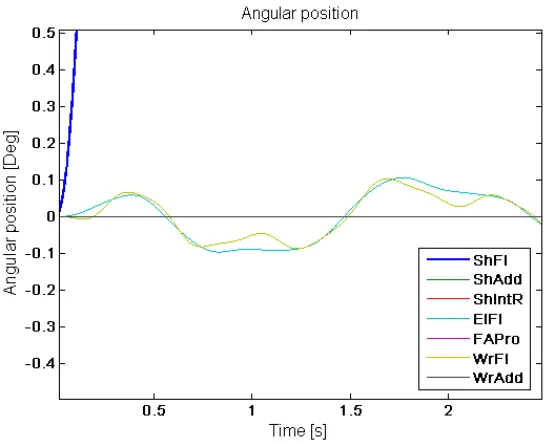
The joint torques are straightforward. The torque for shoulder flexion shows the same profile as the requested movement. Elbow flexion and wrist flexion torques are of equal shape but lower in amplitude as the mass distally from the joint is smaller. Figure 17 shows the resulting simulated movement. The simulated movement seems good. However there is a slight movement at the other flexion joints. This can be seen in Figure 18 where a crop of Figure 17 is presented. Despite the initial conditions there is still a small oscillation of the distal segments. To exclude the integrator as the cause for the behaviour, different integrators and time steps were analysed. These gave the same result and thus it can be said that the integrator or time step is not the cause for the unwanted movements. The results for the other joint movements can be found in Appendix IV.
Figure 18: Forward model new result angular positions crop view
7.4 Sequence of revolute joints
To investigate whether the sequence of the revolute joints have influence on the stability and behaviour of the arm two additional sequences were processed and analysed. The original sequence serves as the reference. The second sequence has adduction and internal rotation in the shoulder, and flexion and pronation at the elbow, interchanged. The order of revolute joints of the third sequence is equal to the original apart from the interchanged pronation and flexion joint at the elbow. As in the analysis of the model behaviour, it is investigated for the actuation of each revolute joint individually. Figure 19 shows the angular position resulting from the forward simulation for the three different sequences for the case of the actuated shoulder adduction. Appendix V discusses the results for other joint actuations.
Looking at the graphs in Figure 19 it can be seen that all sequences give the same good behaviour for the first second. However the reference sequence shows the best result looking at the other joint movements. Near the end, or when the angle starts to deviate from the reference position, other joints start to act up more visibly. The area close to where the arm reaches the ninety degrees is also where the sequence seems to have an influence on the behaviour of the other joints. The second sequence encountered singularities in the simulation this stopped the simulation. A reason for this singularity could be a fast moving segment, causing the time step size to be insufficient. To solve this one could reduce the time step. This however increases the number of calculations and therefore computing time.
7.5 Multi actuation
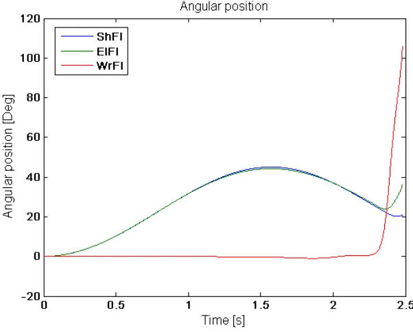
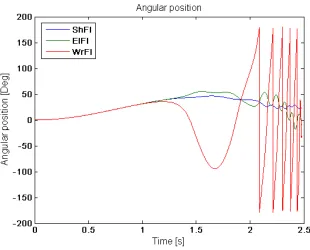
[image:31.595.148.449.271.513.2]Until now only one revolute joint was actuated for the analysis of the model. This section analyses multi actuation of the flexion joints. The result of actuated shoulder and elbow flexion is shown in Figure 20 followed by the result with co-activation of wrist flexion in Figure 21.
Figure 20: Forward model output with actuated shoulder and elbow flexion
The figure above shows the simulated movement of the arm where shoulder and elbow flexion are actuated. Looking at the graph it can be seen that the wrist starts moving with respect to the forearm after 1.2 seconds. Near the end of the 2.48 seconds runtime elbow flexion also starts to deviate from the desired path as wrist begins to rotate. The flexion at the wrist causes the total centre of mass of forearm and hand to shift to the elbow joint. Therefore the required torque to keep the distal segments at their position is lower than the torque exerted on the joint. The excess of torque makes the elbow flexion angle to increase and deviate from the reference position.
8
Discussion
This report mainly comprised the modelling of the upper limb. Modelling of the upper limb is important to better understand the relationship between impairment and human functioning. Partially this can be found by observing the patients however to understand the contribution of each of the mechanisms contributing to the impairment, modelling is essential. With an accurate model, for example, several neurological mechanisms can be tested separately. Eventually the model can be used to evaluate treatments before applying it to a patient, as the model can show the influence of a treatment to the ability to perform ADL. The model build is far from that final goal. The model discussed in this report was build to identify the problems arising from modelling in general and the issues concerning the forward dynamics simulation. This chapter discusses the modelling of the upper limb and the results from the inverse and forward models. Several notes are made on problems arising from the forward dynamics modelling and possible solutions are proposed. Recommendations are treated in the next chapter, future considerations.
8.1 Modelling of the upper limb
In the process of modelling the upper extremity, many assumptions were made to simplify the model. Most important assumption is the use of rigid bodies to model the segments of the upper limb. This makes the computational effort smaller but does not give the ability to accommodate for the changing muscle properties during movement. This change in muscle properties may change the inertia properties and the stiffness of the joints.
In terms of structure, the carrying angle at the elbow is not incorporated in the model as it changes with the flexion angle. Another simplification related to the structure is the definition of the joint centres. Joint centres are taken fixed but in reality they are changing over the range of movement(ROM) of the joint.
Other segment properties that kept the model basic was the exclusion of joint stiffness and boundaries on the joint ROM. Results should therefore be analysed critically, keeping in mind these simplifications. Adding joint stiffness would not simply result in an overall increase in required torques, as joint stiffness is related to the muscle properties and state of muscle activation. Joint ROM can be embedded by using an increasing damped resistance when getting closer to the limit.
All above mentioned simplifications affect the validity of the model. Although most of them are not embedded due to their complexity, restricted ROM was not implemented as it proved to be difficult in SimMechanics. The revolute joints accepted only one input and the ROM restriction block was seen as an input, making it the second input besides the torque actuation block.
In the first check with a hand calculation, unfortunately the InvArm function showed strange behaviour. It could not be retrieved where the sudden sign change originated form. The SimMechanics inverse dynamics model showed better results. Although it slightly deviated from the hand calculation it gave good results especially with angles of 45 and 90 degrees. Possible cause could be the different methods to define the coordinate frames, even though all coordinate frames are oriented equally.
8.2 Discussion on the results
reason, the oscillation might also occur due to an unforeseen fault in the model. Since the oscillations are a probable source of the system becoming instable, certain factors influencing the stability of a system are investigated.
Integrator type and the time step used in the calculation have been excluded in section 7.3 as they showed no change in model behaviour. Since the segment parameters are all fixed and obtained from reliable sources, left to consider is the definition of the coordinate frames and the sequence of the revolute joints. From section 7.4 it can be seen that the sequence of the revolute joints does have an effect on the behaviour. However this is only for activation of shoulder adduction, creating an additional question of why only shoulder adduction movement is affected by joint sequence.
The coordinate frames and how they are defined form the base of the model. Several methods of defining the frames are possible in SimMechanics, Euler angles were chosen for ease of use. However the use of Euler angles introduces the gimbal lock phenomena when using three rotational degrees of freedom at one position, as used for the shoulder joint.
9
Future considerations
In the previous chapters the creation of a model of the upper extremity is discussed. However the model is far from perfect and there are many issues to be considered when proceeding with the modelling of the upper limb. This chapter comprises recommendations for further research on this subject.
With respect to the literature review and the method used to model the arm, the emphasis of the current literature review was on the analysis of upper limb kinematics and kinetics. This resulted in some valuable sources regarding segment parameters and range of the many kinematic and kinetic parameters during ADL. Due to the time constraint insufficient literature search has been done on the methods to model the upper limb. Although the current model gave an idea of the issues arising from modelling of the arm, more sophisticated models are developed which form a better base for future extension of the model with several packages like a muscle model and a neurological control system. A literature study on upper limb modelling is therefore recommended.
To prevent a very complex initial model it is advised to start with the basics and add more complexities to the model when the former model shows good behaviour. For now the rigid body approach is an accurate way to model the arm. When muscle models and neurological control systems are successfully implemented it might be worth trying to make the model with flexible bodies. The muscle model can be used for the generation of the parameters to define change in stiffness within the segments and in the joints.
For the development of a forward dynamics model emphasis is on finding a solution to the inevitable occurrence of instability. To increase the stability, integration algorithm and time step size should be selected carefully and feedback loops should be implemented. It is also recommended not to use Euler angles to define the coordinate frames.
The implementation of a neurological controller introduces several feedback loops. Even though there are many feedback loops the key ones to be considered will be the reflex and force feedback loops. Reflex loops giving positive feedback but opposing the movement and force feedback being negative feedback. These feedback loops will suppress undesired behaviour of the model and thus produce more stability. A neurological controller also gives the ability to model different neurological disorders, attributing to a better understanding of the disorder.
As can be read from the discussion, the Simulink package SimMechanics allows for a quick building of a model. However there are some restrictions to the package not preferable when modelling the upper limb. It should therefore be considered to use a different package, e.g. the robotics toolbox developed by Corke [20], or a complete different approach; not using Simulink.
10
Reference list
1. Wikipedia. Denavit-Hartenberg Parameters. 2010 [cited 2010 November]; Available from: http://en.wikipedia.org/wiki/Denavit-Hartenberg_Parameters.
2. Davies, D.V. and F. Davies, Gray's Anatomy. 33 ed. 1962: Green & Co Ltd.
3. Marieb, E.N. and K. Hoehn, Human anatomy and physiology. 7th ed. 2007, San Francisco: Pearson Benjamin Cummings.
4. Wood, D.E., et al., Biomechanical approaches applied to the lower and upper limb for the
measurement of spasticity: A systematic review of the literature. Disability and
Rehabilitation, 2005. 27: p. 19-32.
5. WEMOVE. Spasticity. 2009 [cited 2010 September]; Available from: http://www.mdvu.org/library/disease/spasticity/.
6. NINDS. Stroke: Hope Through Research. 2010 [cited 2010 September]; Available from: http://www.ninds.nih.gov/disorders/stroke/stroke.htm.
7. NINDS. Cerebral Palsy: Hope Through Research. 2010 [cited 2010 September]; Available from: http://www.ninds.nih.gov/disorders/cerebral_palsy/detail_cerebral_palsy.htm.
8. NINDS. Spinal Cord Injury: Hope Through Research. 2010 [cited 2010 September]; Available from: http://www.ninds.nih.gov/disorders/sci/sci.htm.
9. Malhotra, S., et al., Spasticity, an impairment that is poorly defined and poorly measured. Clinical Rehabilitaion, 2009. 23: p. 651-658.
10. Pandyan, A.D., Spasticity. 2010, Keele University: Keele.
11. Jacquier-Bret, J., N. Rezzoug, and P. Gorce, Reach-to-grasp: a comparative study between
C6-C7 quadriplegic and healthy subjects. Computer Methods in Biomechanics & Biomedical
Engineering, 2008. 11(Journal Article): p. 119-120.
12. Gréa, H., M. Desmurget, and C. Prablanc, Postural invariance in three-dimensional reaching
and grasping movements. Experimental Brain Research.Experimentelle Hirnforschung.ExpAcrimentation CAcrAcbrale, 2000. 134(2): p. 155-162.
13. Marotta, J.J., W.P. Medendorp, and J.D. Crawford, Kinematic Rules for Upper and Lower Arm
Contributions to Grap Orientation. Journal of neurophysiology, 2003. 90(6): p. 3816-3827.
14. Murray, I.A. and G.R. Johnson, A study of the external forces and moments at the shoulder
and elbow while performing every day tasks. Clinical Biomechanics, 2004. 19: p. 586-594.
15. Kontaxis, A., et al., A framework for the definition of standardized protocols for measuring
upper-extremity kinematics. Clinical Biomechanics, 2009. 24: p. 246-253.
16. Buckley, M.A., et al., Dynamics of the upper limb during performance of the tasks of everyday
living--a review of the current knowledge base. Journal of Engineering in Medicine, 1996.
210: p. 241-247.
17. Morrey, B.F., L.J. Askew, and E.Y. Chao, A biomechanical study of normal functional elbow
motion. The Journal of Bone & Joint Surgery, 1981. 63: p. 872-877.
18. Barker, T.M., I.G. Kelly, and J.P. Paul, Three-dimensional joint co-ordination strategies of the
upper limb during functional activities. Journal of Engineering in Medicine, 1996. 210: p.
17-26.
19. Murray, I.A., Determining Upper Limb Kinematics and Dynamics During Every Day Tasks, in
Mechanical, Materials and Manufacturing Engineering. 1999, University of Newcaslte upon
Tyne: Newcastle upon Tyne. p. 470.
20. Corke, P.I., Machine Vision Toolbox. IEEE Robotics and Automation Magazine, 2005. 12(4): p. 16-25.
21. Vicon Motion Systems, Plug-in-Gait Marker Placement. 2010.
22. Naaij, A., Working Space Representations for the Human Upper Limb in motion, in 7th WSEAS
Int. Conf. on APPLIED COMPUTER & APPLIED COMPUTATIONAL SCIENCE (ACACOS '08). 2008:
I.
Protocol
IntroductionIn the pursuit of getting a better understanding of upper limb movements in humans, a model has been developed. With this model the torques in the joints can be computed given the joint angles, angular velocity and acceleration. With the movement data of a movement used in daily activities, the model can be verified with existing literature on this matter. This protocol is based on a framework for the definition of standardized protocols for measuring upper-
![Figure 7: Denavit-Hartenberg example[1]](https://thumb-us.123doks.com/thumbv2/123dok_us/1205127.644033/19.595.313.508.221.435/figure-denavit-hartenberg-example.webp)