NAVAL POSTGRADUATE SCHOOL
Monterey, California
THESIS
Approved for public release; distribution is unlimited USING NETWORK MANAGEMENT SYSTEMS TO DETECT
DISTRIBUTED DENIAL OF SERVICE ATTACKS by
Chandan Singh Negi September 2001
Thesis Advisor: Alex Bordetsky
i
REPORT DOCUMENTATION PAGE Form Approved OMB No. 0704-0188
Public reporting burden for this collection of information is estimated to average 1 hour per response, including the time for reviewing instruction, searching existing data sources, gathering and maintaining the data needed, and completing and reviewing the collection of information. Send comments regarding this burden estimate or any other aspect of this collection of information, including suggestions for reducing this burden, to Washington headquarters Services, Directorate for Information Operations and Reports, 1215 Jefferson Davis Highway, Suite 1204, Arlington, VA 22202-4302, and to the Office of Management and Budget, Paperwork Reduction Project (0704-0188) Washington DC 20503.
1. AGENCY USE ONLY (Leave blank) 2. REPORT DATE September 2001
3. REPORT TYPE AND DATES COVERED Master’s Thesis
4. TITLE AND SUBTITLE: Title (Mix case letters)
Using Network Management Systems To Detect Distributed Denial Of Service Attacks
6. AUTHOR(S)
Chandan Singh Negi
5. FUNDING NUMBERS
7. PERFORMING ORGANIZATION NAME(S) AND ADDRESS(ES) Naval Postgraduate School
Monterey, CA 93943-5000
8. PERFORMING ORGANIZATION REPORT NUMBER
9. SPONSORING / MONITORING AGENCY NAME(S) AND ADDRESS(ES) N/A
10. SPONSORING / MONITORING AGENCY REPORT NUMBER 11. SUPPLEMENTARY NOTES The views expressed in this thesis are those of the author and do not reflect the official policy or position of the Department of Defense or the U.S. Government.
12a. DISTRIBUTION / AVAILABILITY STATEMENT
Distribution Statement (mix case letters)PUT DISTRIBUTION STATEMENT HERE
12b. DISTRIBUTION CODE 13. ABSTRACT (maximum 200 words)
Distributed Denial of Service (DDoS) Attacks have been increasingly found to be affecting the normal functioning of organizations causing billions of dollars of losses. Organizations are trying their best to minimize their losses from these systems. However, most of the organizations widely use the Network Management Systems (NMS) to observe and manage their networks. One of the major functional areas of a NMS is Security Management. This thesis examines how the Network Management Systems could aid in the detection of the DDoS attacks so that the losses from these could be minimized. The thesis details the SNMP MIB variables of importance for detecting these attacks and the MIB signatures of the specific attack.
15. NUMBER OF PAGES
137 14. SUBJECT TERMS
Intrusion Detection, Network Management, Security Management, Denial Of Service, Distributed Denial Of Service Attacks, Trinoo, TFN, TFN2K
16. PRICE CODE 17. SECURITY
CLASSIFICATION OF REPORT
Unclassified
18. SECURITY
CLASSIFICATION OF THIS PAGE Unclassified 19. SECURITY CLASSIFICATION OF ABSTRACT Unclassified 20. LIMITATION OF ABSTRACT UL
NSN 7540-01-280-5500 Standard Form 298 (Rev. 2-89)
ii
iv
v
ABSTRACT
vi
vii
TABLE OF CONTENTS
I. INTRODUCTION...1
A. VULNERABILITIES ...1
B. DISTRIBUTED DENIAL OF SERVICE ATTACKS ...2
C. SECURITY MANAGEMENT WITH NETWORK MANAGEM ENT SYSTEM ...3
II. APPLICATION DOMAIN ...7
A. NETWORK MANAGEMENT SYSTEMS ...7
1. Fault Management ...10
2. Accounting Management ...10
3. Configuration And Name Management ...11
4. Performance Management ...11
5. Security Management ...12
B. SNMP...13
C. DISTRIBUTED DENIAL OF SERVICE ATTACKS ...16
1. Denial of Service Attack Methodology...18
a. Bonk Attack...18
b. Ping of Death Attack...19
c. Smurf Attack/ Syn Flood ...19
d. UDP Flood...19
e. Land Attack ...20
2. Distributed Denial of Service Attacks Methodology...20
a. Trinoo ...20
b. Tribe Flood Network (TFN)...20
c. TFN2K...20
d. Stacheldracht...21
e. Shaft...21
III. RELATED WORK ...23
A. IMPROVING ROUTING ALGORITHMS ...23
B. IP TRACEBACK SCHEMES ...24
1. Packet Based Trace Back ...24
2. ICMP Trace Back Messages (itrace)...24
3. IP Trace Back using Probabilistic Packet Marking ...25
4. Advanced and Authenticated Marking Schemes for IP Trace Back...25
C. INGRESS/ EGRESS FILTERING ( RFC 2267/2827)...26
D. TCP INTERCEPT ...27
E. PACKET FILTERING ...28
F. INTRUSION DETECTION SYSTEMS...29
G. ROUTE-BASED DISTRIBUTED PACKET FILTERING...29
H. THE NOZZLE ...30
viii
IV. EXPERIMENTAL SETUP ...33
A. HYPOTHESIS...33
B. AIM ...33
C. TESTBED ...34
D. METHODOLOGY ...35
1. Using the Spectrum Network Management System...35
2. Using the program ‘miblogger.c’...36
E. ROUND ROBIN DATABASE ...36
F. DESCRIPTION OF THE PROGRAMS ...37
1. Logging of MIB variables values...37
2. Separating the MIB Time Series ...40
3. Plotting the MIB Time Series...42
V. RESULTS ...45
A. TRINOO ...45
1. Changes in the Target MIB variables...46
2. Changes in the Attacker1 MIB variables...48
3. Changes in the Attacker2 MIB variables...49
B. TFN...51
1. Ping (ICMP) Flood...51
a. Changes in the Target MIB variables ...52
b. Changes in the Attacker-1 MIB variables...54
c. Changes in the Attacker-2 MIB variables...55
2. SYN Flood...56
a. Changes in the Target MIB variables ...56
b. Changes in the Attacker-1 MIB variables...57
c. Changes in the Attacker-2 MIB variables...58
3. UDP Flood...59
a. Changes in the Target MIB variables ...60
b. Changes in the Attacker-1 MIB variables...62
c. Changes in the Attacker-2 MIB variables...63
C. TFN2K...64
1. Ping Flood...64
a. Changes in the Target MIB variables ...64
b. Changes in the Attacker-1 MIB variables...67
c. Changes in the Attacker-2 MIB variables...69
2. SYN Flood...71
a. Changes in the Target MIB variables ...71
b. Changes in the Attacker-1 MIB variables...73
c. Changes in the Attacker-2 MIB variables...75
3. UDP Flood...77
a. Changes in the Target MIB variables ...78
b. Changes in the Attacker-1 MIB variables...79
c. Changes in the Attacker-2 MIB variables...81
4. Targa Flood ...83
a. Changes in the Target MIB variables ...84
ix
c. Changes in the Attacker-2 MIB variables...89
5. Mix Flood...91
a. Changes in the Target MIB variables ...91
b. Changes in the Attacker-1 MIB variables...95
c. Changes in the Attacker-2 MIB variables...97
D. SUMMARY...99
VI. CONCLUSIONS AND RECOMMENDATIONS...103
A. CONCLUSIONS ...103
B. RECOMMENDATIONS...104
APPENDIX PROGRAMS ...105
A. MIBLOGGER.C ...105
B. REVERSE.PL...110
C. LOGSEPARATOR.PL...111
D. GRAPHER.PL...112
LIST OF REFERENCES ...115
x
xi
LIST OF FIGURES
Figure 1. Elements of a Network Management System. “From Ref. [STALL]” ...9
Figure 2. Components Of A Distributed Denial Of Service Attack. “From Ref. [BELL - 00]”...17
Figure 3. Ingress/Egress Filtering. ...27
Figure 4. The Nozzle. “From Ref. [STROT-00]”...31
Figure 5. Experimental Setup. ...34
Figure 6. Trinoo Attack - Changes In Target MIB Variables. ...47
Figure 7. Trinoo Attack - Changes In Attacker1 MIB Variables. ...49
Figure 8. Trinoo Attack - Changes In Attacker2 MIB Variables. ...51
Figure 9. TFN Ping Flood Attack - Changes In Target MIB Variables. ...54
Figure 10. TFN Ping Flood Attack - Changes In Attacker1 MIB Variables. ...55
Figure 11. TFN Ping Flood Attack - Changes In Attacker2 MIB Variables. ...56
Figure 12. TFN Syn Flood Attack - Changes In Target MIB Variables...57
Figure 13. TFN Syn Flood Attack - Changes In Attacker1 MIB Variables. ...58
Figure 14. TFN Syn Flood Attack - Changes In Attacker2 MIB Variables. ...59
Figure 15. TFN UDP Flood Attack - Changes In Target MIB Variables. ...62
Figure 16. TFN UDP Flood Attack - Changes In Attacker1 MIB Variables. ...63
Figure 17. TFN UDP Flood Attack - Changes In Attacker2 MIB Variables. ...64
Figure 18. TFN2K Ping Flood Attack - Changes In Target MIB Variables...67
Figure 19. TFN2K Ping Flood Attack - Changes In Attacker1 MIB Variables. ...69
Figure 20. TFN2K Ping Flood Attack - Changes In Attacker2 MIB Variables. ...71
Figure 21. TFN2K Syn Flood Attack - Changes In Target MIB Variables...73
Figure 22. TFN2K Syn Flood Attack - Changes In Attacker1 MIB Variables. ...75
Figure 23. TFN2K Syn Flood Attack - Changes In Attacker2 MIB Variables. ...77
Figure 24. TFN2K UDP Flood Attack - Changes In Target MIB Variables. ...79
Figure 25. TFN2K UDP Flood Attack - Changes In Attacker1 MIB Variables...81
Figure 26. TFN2K UDP Flood Attack - Changes In Attacker2 MIB Variables...83
Figure 27. TFN2K Targa Flood Attack - Changes in Target MIB variables...87
Figure 28. TFN2K Targa Flood Attack - Changes in Attacker1 MIB variables. ...89
Figure 29. TFN2K Targa Flood Attack - Changes in Attacker2 MIB variables. ...91
Figure 30. TFN2K Mix Flood Attack - Changes in Target MIB variables. ...95
Figure 31. TFN2K Mix Flood Attack - Changes in Attacker1 MIB variables. ...97
xii
xiii
LIST OF TABLES
Table 1. Affected MIB Variables In Trinoo Attack...45
Table 2. Affected MIB Variables In TFN Ping Flood Attack. ...51
Table 3. Affected MIB Variables In TFN Syn Flood Attack. ...56
Table 4. Affected MIB Variables In TFN UDP Flood Attack...60
Table 5. Affected MIB Variables In TFN2K Ping Flood Attack. ...64
Table 6. Affected MIB Variables In TFN2K Syn Flood Attack...71
Table 7. Affected MIB Variables In TFN2K UDP Flood Attack. ...77
Table 8. Affected MIB Variables In TFN2K Targa Flood Attack. ...84
Table 9. Affected MIB Variables In TFN2K Mix Flood Attack. ...91
Table 10. Summary Of Affected MIB Variables In Targets In DDoS Attacks. ...100
xiv
xv
ACKNOWLEDGEMENTS
I would first like to thank my parents and my family members for their unconditional love and affection throughout my life, which has given me the inner strength to complete this thesis.
I would also like to express my thanks to my advisors Professor Alex Bordetsky and Paul Clark for their guidance and help. Special thanks goes to Paul Clark for also providing me the resources to complete my experimentation.
xvi
I.
INTRODUCTION
A. VULNERABILITIES
The widespread usage of Internet and networking, whilst increasing the productivity, efficiency and knowledge sharing has resulted in additional problems in the hands of the computer security personnel. The increase in the vulnerability of the systems connected to the Internet is not only due to the fact that more systems are available for the attack, but also due to the fact that more systems are available from which the attack could be carried out. Also, the advancement in technology has provided sophisticated attack tools, which can be used even by people not having much competence. Hence, a day probably does not pass without some sort of compromise in the private networks.
Detection Systems (IDS), Firewalls and Virtual Private Networks (VPNs) are being used by a lot of companies in response to the new threats.
Whilst big corporations do have a dedicated security staff to take care of the security aspect, a large number of computers connected to the Internet at any time are those of a common man who is largely ignorant of all these security aspects. With the falling prices of obtaining a Digital Subscriber Line (DSL) connection or a cable modem connection, more and more such people are having these high-speed connections with the end result that these computers form very lucrative targets for any hacker.
B. DISTRIBUTED DENIAL OF SERVICE ATTACKS
Even though much progress has been made in the field of computer security, new threats seem to be developing for the network. Some of the new threats have focused on the Denial of Service (DoS), which is characterized by an explicit attempt by an attacker to prevent legitimate users of a service from using the desired resources. Examples of DoS attack include attempting to “flood” a network thereby preventing legitimate traffic, attempts to disrupt connections between two machines thereby preventing access to a service, attempts to prevent a particular individual from accessing a service and attempts to disrupt service to a specific system or person.
are tremendous especially to e-commerce sites. According to Jupiter Communications, 46% of consumers report that poor site performance drove them away from their preferred sites. Unacceptable download times often caused by DDoS are estimated to have caused losses of up to $4.35 billion in U.S. e-commerce sales in 1999. And worldwide businesses experienced about 3.3% of unplanned downtime in 1999, translating to $1.6 trillion in lost revenue [EHAT-00].
One of the reasons for the increase in these new types of attacks is as mentioned earlier, the ease of availability of low cost, high speed Internet access to the common man who is not very well- versed with the aspects of computer security. On the technical side, the reason for these attacks is the inherent trusting nature of the Internet. The Internet protocols were not designed with security in mind, and most of the authentication is based on the IP address, which as is well known, can be easily spoofed.
C. SECURITY MANAGEMENT WITH NETWORK MANAGEMENT
SYSTEM
More and more computer systems are being networked, and distributed processing is increasing in importance. Within a given organization, the trend is towards larger, more complex networks supporting more applications and more users. As these networks grow in scale, it becomes increasingly difficult to manage them by human effort alo ne. The complexity of such a system necessitates the use of automated network management tools. Also, since the network of most of the organizations includes equipment from multiple vendors, managing such networks without the aid of such network management tools is nearly impossible.
corporations have some sort of a Network Management System (NMS) in place. A NMS has five major functional areas, Fault Management, Accounting Management, Configuration and Name Management, Performance Management and Security Management. Because of the ever increasing nature of the security attacks and threat, Security Management (SM) is of growing interest in industry and research. Four general methods are used in the SM:
• Scanning a network to determine known security loopholes in a network.
• On-line monitoring of the network to detect any suspicious events.
• Data encryption and secure passwords.
• Firewalls and perimeter defense.
II.
APPLICATION DOMAIN
A. NETWORK MANAGEMENT SYSTEMS
Network and distributed processing systems are of growing importance and have become critical in many areas of our life. Within a given organization, the trend is towards larger, more complex networks supporting more applications and more users. As these networks grow in scale, there are more chances of things going wrong, disabling the network or a portion of the network or degrading performance to an unacceptable level.
A large network cannot be put together and managed by human effort alone. The complexity of such a system necessitates the use of automated network management tools. A Network Management System (NMS) is a collection of tools for network monitoring and control that is integrated in the following senses [STALL].
• It is a single operator interface with a powerful but user- friendly set of commands for performing most or all network management tasks.
• A minimal amount of separate equipment is necessary. That is, most of the hardware and software required for network management is incorporated into the existing user equipment.
management applications for data analysis, fault recovery, and so on. It also has the capability of translating the network manager’s requirement into the actual monitoring and control of elements in the network.
The other active element in the network management system is the management agent. Key platforms such as hosts, bridges, routers, and hubs, may be equipped with the management agents so that they may be managed from the management station. The management agent responds to requests for information and actions from a management station and may asynchronously provide the management station with important but unsolicited information.
The management station and agents are linked by a network management protocol. The protocol used for the management of TCP/IP networks is the Simple Network Management Protocol (SNMP).
Figure 1. Elements of a Network Management System. “From Ref. [STALL]” Network control
host (manager)
Comm Server (agent) Comm Comm WorkStation Router
NMA = network management application NME = network management entity Appl = application
Comm = communiction software OS = operating system
NMA Appl NME
OS
NME Appl
A Network Management System performs the following five key functions: 1. Fault Management
A NMS maintains proper operation of a complex network by :
• Determining exactly where the fault is.
• Isolating the rest of the network from the failure so that it can continue to function without interference.
• Reconfiguring or modifying the network in such a way as to minimize the impact of operation without the failed component or components.
• Repairing or replacing the failed components to restore the network to its initial state.
2. Accounting Management
A NMS allows a network manager to track the use of network resources by end user or end user class. This may be for a number of reasons, including the following:
• An end user or group of end users may be abusing their access privileges and burdening the network at the expense of other end users.
• End users may be making inefficient use of the network, and the network manager can assist in changing procedures to improve performance.
• The network manager is in a better position to plan for network growth if end user activity is known in sufficient detail.
3. Configuration And Name Management
Configuration management is concerned with initializing a network and gracefully shutting down part or all of the network. It is also concerned with maintaining, adding, and updating the relationships among components and the status of components themselves during network operation. When changes in configuration occur, end users should be notified of these changes. Configuration reports can be generated either on some routine periodic basis or in response to a request for such a report. Before reconfiguration, end users often want to inquire about the upcoming status of resources and their attributes. Network managers usually want only authorized end users (operators) to manage and control network operation.
4. Performance Management
Performance management of a computer network comprises two broad functional categories – monitoring and controlling. Monitoring is the function that tracks activities on the network. The controlling function enables performance management to make adjustments to improve network performance. Some of the performance issues of concern to the network manager are:
• What is the level of capacity ut ilization?
• Is there excessive traffic?
• Has throughput been reduced to unacceptable levels?
• Are there bottlenecks?
Performance management, must therefore, monitor many resources to provide information in determining network operating level. By collecting this information, analyzing it, and then using the resultant analysis as feedback to the prescribed set of values, the network manger can become more adept at recognizing situations indicative of present or impending performance degradation. The NMS should be able to give the average and worst-case response times and the reliability of the network services. Thus, performance must be known in sufficient detail to assess specific end user queries. Performance statistics are used by the network managers to help them plan, manage and maintain large networks. Performance statistics can be used to recognize potential bottlenecks before they cause problems to the end users. Appropriate corrective action can then be taken. This action can take the form of changing routing tables to balance or redistribute traffic load during times of peak use or when a bottleneck is identified by a rapidly growing load in one area.
5. Security Management
Security Management keeps account of activity, or attempted activity, with these security objects in order to detect and recover from attempted or successful security attacks. This includes the following functions related to the maintenance of security information:
• Event logging
• Monitoring security audit trails
• Monitoring usage and users of security-related resources
• Reporting security violations
• Receiving notification of security violations
• Maintaining and examining security logs
• Maintaining backup copies for all or part of the security-related files
• Maintaining general network user profiles, and usage profiles for specific resources, to enable references for conformance to designated security profiles Security management manages the access-control service by maintaining general network user profiles and usage profiles for specific resources and by setting priorities for access. The security management function enables the user to create and delete security related objects, change their attributes or state, and affect the relationships between security objects.
B. SNMP
broad spectrum of product types, including end systems, bridges, routers, and telecommunications equipment increases. In response to this need, the simple network management protocol (SNMP) was developed to provide a tool for multi- vendor, interoperable network management [STALL]. SNMP includes the following key capabilities:
• get - enables the management station to retrieve the value of objects at the agent.
• set - enables the management station to set the value of objects at the agent.
• trap - enables an agent to notify the management station of significant events.
Resources in the network are managed by representing them as objects, which are essentially data variables that represent different aspects of the managed agent. This collection of objects is referred to as a Management Information Base (MIB). The MIB functions as a collection of access points at the agent for the management station. All of the values that are stored in the MIB are dynamic and are not stored in any file or registry key. The information stored in the MIBs ranges from Object IDs (OIDs) to Protocol Data Units (PDUs). The MIBs must be located at both the agent and the manager to work effectively.
own set of MIBs, but these need to be made available at the agent as well as at the NMS. The standard core management information is given in RFC1213.
Information stored by agents is made available to the management system by means of the following two techniques:
• Polling - Polling is a request-response interaction between a manager and agent. The manager can query any agent (for which it has authorization) and request the values of various information elements; the agent responds with information from its MIB. The request may be specific, listing one or more named variables. A request may also be in the nature of search, asking the agent to report information matching certain criteria, or to supply the manager with information about the structure of the MIB at the agent. A manager system may use polling to learn about the configuration it is managing, to obtain periodically an update of conditions, or to investigate an area in detail after being alerted to a problem.
This thesis used only polling as a means to determine the changes taking place in the various variables in response to the DDoS attacks. However, there exists a possibility to modify the agents, to add some sort of intelligence in the agents, so as to raise a trap on seeing some sudden variation (as mentioned in conclusions and future works).
C. DISTRIBUTED DENIAL OF SERVICE ATTACKS
A denial of service attack is characterized by an explicit attempt by an attacker to prevent legitimate users from using resources. Examples of denial of service attacks include [STROT-00]:
• attempts to “flood” a network, thereby preventing legitimate network traffic
• attempts to disrupt connections between two machines, thereby preventing access to a service
• attempts to prevent a particular individual from accessing a service
• attempts to disrupt service to a specific system or person.
A distributed format amplifies these attacks by adding a “many to one” dimension to these attacks, making them more difficult to prevent. A distributed denial of service attack is composed of four elements, as shown in the Figure 2 [BELL –00].
• A victim - A victim is a target host that has been chosen to receive the brunt of the attack.
host computers. The task of deploying these attack daemons requires the attacker to gain access and infiltrate the host computers.
Figure 2. Components Of A Distributed Denial Of Service Attack. “From Ref. [BELL - 00]”
• Control master program - Its task is to coordinate the attack and is deployed in a host (master).
• Real attacker - The mastermind behind the attack. By using a control master program, the real attacker can stay behind the scenes of the attack [LAU -00]. The DDOS attack sequence is as follows.
• The real attacker sends an “execute” message to the control master program.
Slave
Master
Real Attacker
Victim
Slave
Slave
Slave
• The control master program receives the “execute” message and propagates the command to the attack daemons under its control.
• Upon receiving the attack command, the attack daemons begin the attack on the victim.
Even though it might appear that the real attacker doesn’t have much to do except to send out the “execute” command, in reality he/she actually has to plan the execution of a successful distributed denial of service attack. The attacker must infiltrate all the host computers and networks where the daemon attackers are to be deployed. The attacker must study the target’s network topology and search for the bottlenecks and vulnerabilities that can be exploited during the attack. Because of the use of attack daemons and control master programs, the real attacker is not directly involved during the attack, which makes it difficult to trace who spawned the attack.
1. Denial of Service Attack Methodology
Some of the widely known basic denial of service attack methods that are emplo yed are as follows [STROT - 00]. These attacks take advantage of the inherent flaws in the networking protocols.
a. Bonk Attack
b. Ping of Death Attack
This attack is aimed at the ICMP echo request. ICMP is used with a small payload to provide a fast, low bandwidth test of connectivity. Because of this typical usage, some software do not handle large payloads. If such software receives an ICMP request packet with a payload greater than 4000 bytes the software generates an exception and halts communication on the network.
c. Smurf Attack/ Syn Flood
In any TCP operation, before the handshake is complete, the receiver has no idea how long the propagation delay is between itself and the other machine. Therefore, once sending the ACK-SYN packet it will wait longer than usual (often up to 2 minutes) to receive a response. An attacker takes advantage of this and doesn’t respond to the ACK-SYN packets. Thus the receiver will have to store information necessary to correlate the expected ACK response with the packet sent. There is a limited amount of space storage so if enough packets are received, without any response to the ACK-SYN packets then this space will be exhausted and the machine will cease to receive any additional SYN request. Therefore, no valid connections can be made during this period.
d. UDP Flood
e. Land Attack
In this case the source and the destination address are the same, and so the victim consumes all its resources talking to itself, and thereby blocks out side conversations.
2. Distributed Denial of Service Attacks Methodology
In this section the various methods employed by the attackers in the various distributed of denial service (DDoS) attacks are discussed [DITT -99], [DITT -00], [BARL-00].
a. Trinoo
The communication between the master and the slaves is using TCP, whereas the communication with the attack daemons is using the UDP packets. The attack implemented is UDP flood.
b. Tribe Flood Network (TFN)
Communication between the master and the slaves is using ICMP echo reply packets. The attack could be of smurf, SYN flood, UDP flood and ICMP flood attacks.
c. TFN2K
d. Stacheldracht
It is based on the TFN attack. The communication between the master and the slave is encrypted and uses TCP and ICMP. In this case also the attacks implemented are the same as TFN.
e. Shaft
III. RELATED WORK
The area of the distributed denial of service attacks has been the focus of much research. Much study has been done ranging from the analysis of the various common DDoS tools available to the simulation and proposals for solving the problems. Solutions to DDoS are especially difficult because of the ability of the DDoS tools to spoof the IP address and/or the port numbers. The usage of cryptography in the attack further complicates the issues. In fact, many experts have stated that there are currently no successful defenses against a fully distributed denial of service attack. Nevertheless some of these works are discussed here, which propose some of the actions we can take to minimize the impact of the DDoS attacks.
A. IMPROVING ROUTING ALGORITHMS
B. IP TRACEBACK SCHEMES
Some researchers have studied the methodology for tracing back the attacker. The basis of these studies is that the DDoS attacks are on the rise because of the difficulty in tracing back the attacking source. There have been many proposals to determine the attacking hosts in spite of usage of address spoofing techniques to disguise the source of origin. These proposals help determine the attacking hosts, not the actual attacker, because the attacker might be hiding in some other host and sends the attack command, much before the attack builds up. Some of these proposals are discussed below:
1. Packet Based Trace Back
In packet-based trace back, packets are marked with the addresses of intermediate routers. The victim can use the information inscribed in packets to trace the attack back to its source. The drawback of this method is the overhead resulting from the increase in the number of packets.
2. ICMP Trace Back Messages (itrace)
3. IP Trace Back using Probabilistic Packet Marking
In this approach, the routers are allowed to probabilistically mark the packets with partial path information during packet forwarding. The victim can then reconstruct the complete path after receiving a modest number of packets containing the marking [SAVA-00]. This approach has low overhead for routers and supports incremental deployment, however it has a very high computation overhead for the victim to reconstruct the attack paths. Another problem with this approach is that it has mainly considered the denial-of-service with a single attacker site. The scheme becomes inefficient and gives inaccurate results even under a minor increase in scale.
4. Advanced and Authenticated Marking Schemes for IP Trace Back
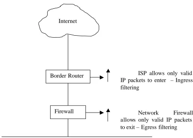
C. INGRESS/ EGRESS FILTERING ( RFC 2267/2827)
Ferguson and Senie proposed ingress filtering in which only valid IP packets from a valid source address are allowed by the routers to enter the Internet [FERG - 98]. Ingress traffic filtering at the periphery of Internet connected networks will reduce the effectiveness of source address spoofing denial of service attacks. The problem with this approach is that it requires the router to ha ve sufficient power to verify the IP address of each packet and to have sufficient knowledge to distinguish between legitimate and illegitimate addresses. Also, the approach is effective only if deployed at a large scale.
Figure 3. Ingress/Egress Filtering.
D. TCP INTERCEPT
Cisco has implemented a feature called TCP Intercept to protect TCP servers from TCP SYN – flooding attacks by intercepting and validating TCP connection requests [CISC -99]. It can be used in two modes. In the intercept mode, the TCP synchronization (SYN) packets from clients to servers are intercepted by the software and a connection established on behalf of the destination server. If the connection is successful then the software establishes the connection with the server on behalf of the client and knits the two half connections transparently. Thus connection attempts from unreachable hosts will never reach the server. The software continues to intercept and forward packets
Internal Network
ISP allows only valid IP packets to enter – Ingress filtering
Border Router
Firewall Internet
throughout the duration of the connection. In the case of illegitimate requests, the software goes into aggressive timeout modes for the half connections.
TCP intercept can also be used in watch mode, in which the software passively watches the connection requests flowing through the router. If a connection fails to get established in a configurable interval, the software intervenes and terminates the connection attempt.
Thus, only the valid connection requests are allowed. Illegitimate requests and half-open connections are discarded by having timeouts or resets. When under attack, the TCP intercept feature becomes more aggressive in its protective behavior.
E. PACKET FILTERING
Packet filtering is a network security mechanism for controlling what data can flow to and from network affected routers or firewalls. A firewall is a system deployed between the company’s network and the Internet and has the ability to observe and control all the incoming/outgoing packets.
F. INTRUSION DETECTION SYSTEMS
Intrusion Detection Systems (IDS) monitor the network for known attack signatures. An attack signature is a sequence of events, which is known to occur prior to or during an attack. IDS have been used to prevent some of the DDoS attacks, but they have their own limitations. There is no way of knowing the attack signature until at least one site has been attacked. Moreover, the attack signature based on the port number of the attack does not seem to be very effective in light of the new developments in the field of the DDoS tools, in which the port number as well as the protocols used are random in nature. IDS, which observe traffic for attack signatures are known as knowledge-based systems.
If the system has the ability to learn attack signatures, it is called a behavior based IDS. Problem with behavior-based systems is that to be effective the learning should be in real time, which is difficult to achieve. Another problem with behavior based ID systems is false positives reports. Whenever a system attempts to learn a behavior at the same time as guarding against the behavior it runs the risk of falsely identifying an occurrence. In most networks, the number of false positives must be sufficiently low so as not to disrupt normal communications.
G. ROUTE-BASED DISTRIBUTED PACKET FILTERING
reaching other autonomous systems. This approach doesn’t require expanding IP header fields to encode stamped link information [PARK-00]. However, it does require compliance by a number of different autonomous systems to be effective.
H. THE NOZZLE
Figure 4. The Nozzle. “From Ref. [STROT-00]”
The nozzle’s performance is dependent on how it is configured.
I. CENTERTRACK
IV.
EXPERIMENTAL SETUP
A. HYPOTHESIS
Joao B.D. Cabrera, Lundy Lewis et al. proposed a methodology in which a Network Management System can be used for early detection of Distributed Denial of Service attacks [JOAO – 01]. Their hypothesis is that even though there are quite large number of events that are prior to an attack (e.g. suspicious logons, start of processes, addition of new files, sudden shifts in traffic, etc.), a DDoS attack could be detected on the basis of shifts in the traffic patterns in some of the Management Information Base (MIB) variables collected from the systems participating in the attack. Using domain knowledge an experiment was carried out and it was observed by them that there are indeed MIB-based precursors of DDoS attacks, that makes it possible to detect the attack before the target is shut down. They have also described how the relevant MIB variables at the attacker can be extracted automatically using Statistical tests for Causality. That is, out of the various variables at the target and the attacker, which change over a period of time, during a DDoS attack, the main variables which need to be monitored at the attacker can be determined, which can then be used for detecting in advance, any machine participating in the attack, using a simple anomaly detection scheme of the rate of change of these key variables.
B. AIM
the MIB variables, which change over a period of time during the DDoS attack in an experimental test bed and determine the key MIB variables, which should be observed for monitoring.
An offshoot of this experiment would also be to determine if the type of DDOS attack could be identified by the observed type of the changes in the MIB variables (e.g. if it is DOS SYN flood, or UDP flood etc.) so that a possibility exists of an entirely automated procedure centered on Network Management systems for detecting precursors of Distributed Denial of Service Attacks, and responding to them.
C. TESTBED
The experimental setup for the test bed consisted of a local area network as shown in Figure 5.
Figure 5. Experimental Setup.
Red Hat Linux Red Hat Linux Red Hat Linux Win2K Professional
The Network Management system used was the Spectrum Network Management system, manufactured by M/S Aprisma Technologies limited. The Operating system was the Sun Solaris 7.0. Two Red Hat Linux hosts were used as attackers and the target was the Windows 2000 professional system. The third Red Hat Linux host had the various programs and was used to observe the MIB variables.
The attacking hosts were inserted with the DDoS zombie codes. In reality, before carrying out the attack, the attacker would have to impregnate the attackers with the zombie code and then from a master computer would give a command to attack the target. However in this thesis the attacking hosts were assumed to have been infected already and the master computer (needed for some attacks for giving a command) was external to the setup.
D. METHODOLOGY
1. Using the Spectrum Network Management System
2. Using the program ‘miblogger.c’
In the second approach, a program miblogger.c was written using the ucd-snmp development library available with the Red Hat Linux and compiled and run on the same platform (the third Linux box, different from the two attackers). The list of MIBs to be queried was taken from the shortlist obtained from the first approach. The program queried the attackers and the target for the value of these MIBs at a regular interval of five seconds. The system time and the response obtained were recorded in a separate log file for each host (but containing all the shortlisted MIBs). Perl scripts were used to separate the logged MIBs into separate log files and to create the Round-Robin-Databases (RRDs) using the RRD perl module. The graphing function of the RRDtool was used to generate the graphs.
E. ROUND ROBIN DATABASE
Round Robin Database (RRD) [TOBI-00] is a system to store and display time-series data (i.e. network bandwidth, machine-room temperature, server load average). It stores the data in a very compact way that will not expand over time, and it presents useful graphs by processing the data to enforce a certain data density. It can be used either via simple wrapper scripts (from shell or Perl) or via frontends that poll network devices and put a friendly user interface on it.
After a while, when all the available places are used, the process automatically reuses old locations. This way, the database does not grow in size and therefore requires no maintenance. RRDtool works with Round Robin Databases (RRDs). It stores and retrieves data from them.
On disk, the round robin database (RRD) is organized into sequential sections, called round robin archives (RRA). Within each RRA is a section for each of the data sources (input) stored in this RRD. Each RRA is defined by a consolidation function which maps primary data points (PDP) to consolidated data points (CDP), which are then plotted. The consolidation function could be the MAX, MIN, LAST or AVERAGE of the values.
In this thesis the RRDtool is used for generating the RRD databases, updating them with the logged data and for creating graphs in the ‘gif’ format. The RRD perl module and simple perl scripts are used for this purpose.
F. DESCRIPTION OF THE PROGRAMS
1. Logging of MIB Variables Values
The program used to collect and log the values of the MIB variables was ‘miblogger.c’ in RedHat linux 7.0 (Kernel 2.2.16-22) and the GNU compiler gcc version 2.96. The program uses the UCD-SNMP library (also known as NET-SNMP). The library is freely available and also comes with the standard Red-Hat installation.
Initially load the various header files.
#include <ucd-snmp/ucd-snmp-config.h> #include <ucd-snmp/ucd-snmp-includes.h> #include <sys/time.h>
The polling interval is defined to be 5s and the total poll duration is for 20 minutes (20 x 60 / 5). This is a reasonable interval since the DDoS attacks result in very sudden large changes in the MIB variables.
#define POLL_INTERVAL 5 #define POLL_COUNT 240
A list of hosts and their type (whether target or attacker) is declared and populated. The type is required because the MIB variables to be observed for the attacker and the target are different. The list of the MIB variables to be observed for both the type of hosts was determined by both the domain knowledge of the attacks as well as by observing them with a MIB browser when under attack.
struct host { char *name; char *type; }
struct oid { char *Name; oid Oid[MAX_OID_LEN]; int OidLen;
The main() routine first calls the initialize() subroutine which initializes the snmp library. It also reads the various MIB variables and correlates them with their oid number, thus ensuring that they are correct, returning error if incorrect.
init_snmp("miblogger"); .
.
while (op->Name) {
op->OidLen = sizeof(op->Oid)/sizeof(op->Oid[0]); if (!read_objid(op->Name, op->Oid, &op->OidLen)) { snmp_perror("read_objid");
exit(1); }
}
• struct snmp_session – A structure that holds information about the host which is to be queried. Two of these structures need to be declared, one to fill with information and the second a pointer returned by the library.
• struct snmp_pdu – This structure holds all of the information that is sent (received) to (from) the remote host.
• struct oid – The pointer for the oid. Could be oid_T (target) or oid_A (attacker).
• FILE *f – The log file. The log file is different for each host.
The snmp-session is then initialized which prepares the input session data. The first call to snmp_sess_init() initializes the Library, including the MIB parse trees, before any SNMP sessions are created. The structure is populated with the snmp version type (v1, v2c, v3 – v2c is used in the program as it is the most common one and has wide spread support), the name of the host and the snmp community name) and a session is then setup with the call snmp_synch_setup().
snmp_sess_init(&ss);
ss.version = SNMP_VERSION_2c; ss.peername = hp->name;
ss.community = "public"; snmp_synch_setup(&ss);
After establishing a session, it is opened. Opening it returns a pointer to another session that is used in all the future calls.
sp = snmp_open(&ss)
value for each of the specified oid. A NULL value needs to be added to each oid for all outgoing requests. This is achieved by the
snmp_add_null_var(req, op->Oid, op->OidLen);
Finally, the request is sent using the session pointer and the pdu. A status and a response is returned which is stored in the second snmp_pdu (*resp) structure declared earlier.
status = snmp_synch_response(sp, req, &resp);
The returned response, status, session pointer and the log file name are then passed to the log_response() subroutine for logging purpose. The returned values are logged only if there is no error (status = STAT_SUCCESS and response-> == SNMP_ERR_NOERROR). A new line is added to the log files after recording the group of MIB values at a particular time, to facilitate the parsing of the log files easily.
2. Separating the MIB Time Series
The script reverse.pl takes the log file and creates another file in which the data is in the reverse order. The second script is given this reversed log file as the input and it splits it into the various MIB values recorded in the log file.
Open the log file first:
open(LOG,"<$file") or die "could not open file";
Go through the file and determine the number of MIB variables in the log file, the group of MIB variables is separated in the log file by a new line character. The script looks for the first character in the line and if it is the new- line character then it exits the loop.
while(<LOG>) { if ($_ !~ /^\n/){
chomp;
($time,$ipadd,$mib_n_value) = split /:/; print "min_n_value = $mib_n_value\n"; ($mib,$count) = split / = /, $mib_n_value; ($f,$m,$l) = split /\./, $mib;
print "The value of log file name is $m.log\n"; sleep 1;
$array[$no] = $m.".log";
print "The value of $no element in array is $array[$no]\n"; $no++;
}
else {last;} }
close(LOG);
$max_no_of_mibs = $no;
Determine the names of the MIB variables logged in the file and then create corresponding log files for each of them.
for ($x = 1; $x <= $max_no_of_mibs; $x++) {
open(OUT."$x", ">". $array[$x -1]) || die "couldn't open $x.log \n"; }
open(LOG,"<$file") or die "could not open file"; while(<LOG>) {
if ($_ !~ /^\n/) { chomp;
if ($x > $max_no_of_mibs) { $x = 1; } ($time,$ipadd,$mib_n_value) = split /:/; ($mib,$count) = split / = /, $mib_n_value;
print "Updating $x.log\n"; $FH = OUT."$x";
print $FH "$time:$count\n"; $x++;
} }
close(LOG);
3. Plotting the MIB Time Series
The time series for each of the MIB variable is plotted using the RRD tool described earlier. It requires the usage of the perl::RRD module.
Use the perl RRD module.
use RRDs; use strict;
Open the log file and determine the start time and the end time of the logging.
open(LOG,"<$file") or die "could not open file"; my($cnt)=1;
while(<LOG>) { chomp;
($time,$count) = split /:/;
if ($cnt <2) { $start_time = $time-10;} $end_time = $time;
$cnt++; }
Create and update the round-robin database for each of the MIB variable and print error if any.
RRDs::create ($fname.".rrd"," --start",$start_time, " --step",5, "DS:a:COUNTER:10:U:U",
"RRA:AVERAGE:0.5:1:600"); $ERROR = RRDs::error;
die "$0: unable to create '$fname.'.rrd: $ERROR\n" if $ERROR; print "Updating $fname.rrd\n";
open(LOG,"<$file") or die "could not open file" ; while(<LOG>) {
chomp;
RRDs::update ($fname.".rrd", $_); if ($ERROR = RRDs::error) {
die "$0: unable to update $fname.rrd: $ERROR\n"; };
}
close(LOG);
Draw the graphs in gif format.
RRDs::graph ("$fname.gif"," --start", $start_time, "--end", $end_time," --title", "TFN_Syn_Flood - Rate of change of $fname with time", "--vertical-label", "$fname(/s)","DEF:mibvalue=$fname.rrd:a:AVERAGE",
"LINE1:mibvalue#FF0000:\rAverage change in $fname per second"); if ($ERROR = RRDs::error) {
V.
RESULTS
This chapter describes the results of the experiments carried out on the experimental setup. The results identify the affected MIB variables at the attackers and at the target for each of the DDoS attack and also graphically illustrate the change in these before during and after attack. The key variables (those which show large changes) are highlighted. The attacks considered in the experiment were the Trinoo, TFN and the TFN2K attacks. The graphical results clearly indicate the sudden abrupt change in the key MIB variables during the attack.
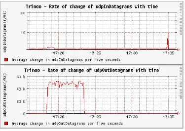
A. TRINOO
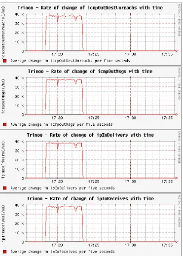
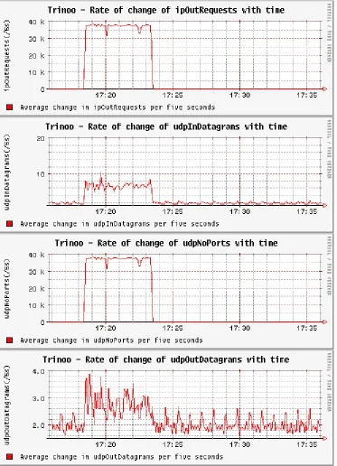
The affected variables at the target and at the attacker in a trinoo attack are shown in table 1.
Sl. No. Target Attacker
1. icmp.icmpOutDestUnreachs.0 icmp.icmpInDestUnreachs.0
2. icmp.icmpOutMsgs.0 icmp.icmpInMsgs.0
3. ip.ipInDelivers.0 ip.ipInDelivers.0
4. ip.ipInReceives.0 ip.ipI nReceives.0
5. ip.ipOutRequests.0 ip.ipOutRequests.0
6. udp.udpInDatagrams.0 udp.udpInDatagrams.0
7. udp.udpNoPorts.0 udp.udpOutDatagrams.0
8. udp.udpOutDatagrams.0
1. Changes in the Target MIB Variables
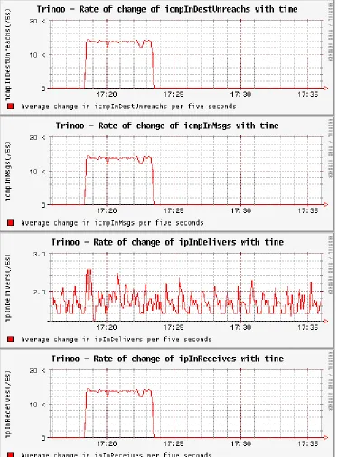
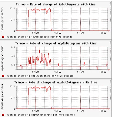
2. Changes in the Attacker1 MIB Variables
Figure 7. Trinoo Attack - Changes In Attacker1 MIB Variables.
3. Changes in the Attacker2 MIB Variables
Figure 8. Trinoo Attack - Changes In Attacker2 MIB Variables.
B. TFN
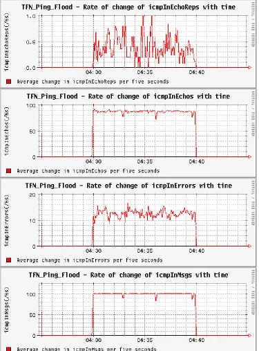
1. Ping (ICMP) Flood
The affected variables at the target and at the attacker in a TFN ping- flood attack are shown in table 2.
Sl. No. Target Attacker
1. icmp.icmpInEchoReps.0 icmp.icmpInEchoReps.0
2. icmp.icmpInEchos.0 icmp.icmpInMsgs.0
3. icmp.icmpInErrors.0 ip.ipOutRequests.0
4. icmp.icmpInMsgs.0
5. icmp.icmpOutEchoReps.0
6. icmp.icmpOutMsgs.0
[image:68.612.126.501.70.335.2]7. ip.ipInDelivers.0 8. ip.ipInReceives.0 9. ip.ipOutRequests.0 10. udp.udpNoPorts.0
a. Changes in the Target MIB Variables
Figure 9. TFN Ping Flood Attack - Changes In Target MIB Variables.
b. Changes in the Attacker-1 MIB Variables
Figure 10. TFN Ping Flood Attack - Changes In Attacker1 MIB Variables.
c. Changes in the Attacker-2 MIB Variables
Figure 11. TFN Ping Flood Attack - Changes In Attacker2 MIB Variables.
2. SYN Flood
The affected variables at the target and at the attacker in a TFN syn-flood attack are shown in table 3.
Sl. No. Target Attacker
1. ip.ipInDelivers.0 icmp.icmpInEchoReps.0
2. ip.ipInReceives.0 icmp.icmpInMsgs.0
3. tcp.tcpInErrs.0 ip.ipOutRequests.0
4. tcp.tcpInSegs.0
Table 3. Affected MIB Variables In TFN Syn Flood Attack.
a. Changes in the Target MIB Variables
Figure 12. TFN Syn Flood Attack - Changes In Target MIB Variables.
b. Changes in the Attacker-1 MIB Variables
Figure 13. TFN Syn Flood Attack - Changes In Attacker1 MIB Variables.
c. Changes in the Attacker-2 MIB Variables
Figure 14. TFN Syn Flood Attack - Changes In Attacker2 MIB Variables.
3. UDP Flood
The affected variables at the target and at the attacker in a TFN UDP-Flood attack are shown in table 4.
Sl. No. Target Attacker
1. icmp.icmpInDestUnreachs.0 icmp.icmpInEchoReps.0
2. icmp.icmpInMsgs.0 icmp.icmpInMsgs.0
3. icmp.icmpOutDestUnreachs.0 ip.ipOutRequests.0
5. ip.ipInDelivers.0 6. ip.ipInReceives.0 7. ip.ipOutRequests.0 8. udp.udpInErrors.0 9. udp.udpNoPorts.0
Table 4. Affected MIB Variables In TFN UDP Flood Attack.
a. Changes in the Target MIB variables
Figure 15. TFN UDP Flood Attack - Changes In Target MIB Variables.
b. Changes in the Attacker-1 MIB Variables
Figure 16. TFN UDP Flood Attack - Changes In Attacker1 MIB Variables.
c. Changes in the Attacker-2 MIB Variables
Figure 17. TFN UDP Flood Attack - Changes In Attacker2 MIB Variables.
C. TFN2K
1. Ping Flood
The affected variables at the target and at the attacker in a TFN2K ping- flood attack are shown in table 5.
Sl. No. Target Attacker
1. icmp.icmpInEchoReps.0 icmp.icmpInEchoReps.0
2. icmp.icmpInEchos.0 icmp.icmpInMsgs.0
3. icmp.icmpInErrors.0 ip.ipInDelivers.0
4. icmp.icmpInMsgs.0 ip.ipInReceives.0
5. icmp.icmpOutEchoReps.0 ip.ipOutRequests.0
6. icmp.icmpOutMsgs.0 tcp.tcpInSegs.0
7. ip.ipInDelivers.0 udp.udpInErrors.0
8. ip.ipInReceives.0 9. ip.ipOutRequests.0 10. udp.udpNoPorts.0
Table 5. Affected MIB Variables In TFN2K Ping Flood Attack.
a. Changes in the Target MIB Variables
Figure 18. TFN2K Ping Flood Attack - Changes In Target MIB Variables.
b. Changes in the Attacker-1 MIB Variables
Figure 19. TFN2K Ping Flood Attack - Changes In Attacker1 MIB Variables.
c. Changes in the Attacker-2 MIB Variables
Figure 20. TFN2K Ping Flood Attack - Changes In Attacker2 MIB Variables.
2. SYN Flood
The affected variables at the target and at the attacker in a TFN2K syn- flood attack are shown in table 6.
Sl. No. Target Attacker
1. ip.ipInDelivers.0 icmp.icmpInEchoReps.0
2. ip.ipInReceives.0 icmp.icmpInMsgs.0
3. ip.ipOutRequests.0 ip.ipInReceives.0
4. tcp.tcpInSegs.0 ip.ipInDelivers.0
5. tcp.tcpInErrs.0 ip.ipOutRequests.0
6. tcp.tcpOutRsts.0 tcp.tcpInSegs.0
7. tcp.tcpOutSegs.0 udp.udpInErrors.0
Table 6. Affected MIB Variables In TFN2K Syn Flood Attack.
a. Changes in the Target MIB Variables
Figure 21. TFN2K Syn Flood Attack - Changes In Target MIB Variables.
[image:90.612.126.500.72.329.2]b. Changes in the Attacker-1 MIB Variables
Figure 22. TFN2K Syn Flood Attack - Changes In Attacker1 MIB Variables.
[image:92.612.126.500.71.331.2]c. Changes in the Attacker-2 MIB Variables
Figure 23. TFN2K Syn Flood Attack - Changes In Attacker2 MIB Variables.
3. UDP Flood
The affected variables at the target and at the attacker in a TFN2K UDP-Flood attack are shown in table 7.
Sl. No. Target Attacker
1. icmp.icmpOutDestUnreachs.0 icmp.icmpInEchoReps.0
2. icmp.icmpOutMsgs.0 icmp.icmpInMsgs.0
3. ip.ipInDelivers.0 ip.ipInReceives.0
4. ip.ipInReceives.0 ip.ipInDelivers.0
5. ip.ipOutRequests.0 ip.ipOutRequests.0
6. udp.udpInErrors.0 tcp.tcpInSegs.0
7. udp.udpNoPorts.0 udp.udpInErrors.0
a. Changes in the Target MIB Variables
Figure 24. TFN2K UDP Flood Attack - Changes In Target MIB Variables.
b. Changes in the Attacker-1 MIB Variables
Figure 25. TFN2K UDP Flood Attack - Changes In Attacker1 MIB Variables.
[image:98.612.125.501.72.331.2]c. Changes in the Attacker-2 MIB Variables
Figure 26. TFN2K UDP Flood Attack - Changes In Attacker2 MIB Variables.
4. Targa Flood
The affected variables at the target and at the attacker in a TFN2K Targa-Flood attack are shown in table 8.
Sl. No. Target Attacker
1. icmp.icmpInDestUnreachs.0 icmp.icmpInEchoReps.0
2. icmp.icmpInErrors.0 icmp.icmpInMsgs.0
3. icmp.icmpInMsgs.0 ip.ipInDelivers.0
4. icmp.icmpOutDestUnreachs.0 ip.ipInReceives.0
5. icmp.icmpOutMsgs.0 ip.ipOutRequests.0
6. ip.ipInDelivers.0 tcp.tcpInSegs.0
7. ip.ipInReceives.0 udp.udpInErrors.0
8. ip.ipInUnknownProtos.0 udp.udpOutDatagrams.0
13. tcp.tcpInSegs.0 14. udp.udpInErrors.0 15. udp.udpNoPorts.0 16. udp.udpOutDatagrams.0
Table 8. Affected MIB Variables In TFN2K Targa Flood Attack.
a. Changes in the Target MIB Variables
Figure 27. TFN2K Targa Flood Attack - Changes in Target MIB Variables.
b. Changes in the Attacker-1 MIB Variables
Figure 28. TFN2K Targa Flood Attack - Changes in Attacker1 MIB Variables.
c. Changes in the Attacker-2 MIB Variables
Figure 29. TFN2K Targa Flood Attack - Changes in Attacker2 MIB Vvariables.
5. Mix Flood
The affected variables at the target and at the attacker in a TFN2K mix- flood attack are shown in table 9.
Sl. No. Target Attacker
1. icmp.icmpInEchoReps.0 icmp.icmpInEchoReps.0
2. icmp.icmpInEchos.0 icmp.icmpInMsgs.0
3. icmp.icmpInErrors.0 ip.ipInDelivers.0
4. icmp.icmpInMsgs.0 ip.ipInReceives.0
5. icmp.icmpOutDestUnreachs.0 ip.ipOutRequests.0
6. icmp.icmpOutEchoReps.0 tcp.tcpInSegs.0
7. icmp.icmpOutMsgs.0 udp.udpInErrors.0
[image:108.612.86.527.343.593.2]8. ip.ipInDelivers.0 9. ip.ipInReceives.0 10. ip.ipOutRequests.0 11. tcp.tcpInErrs.0 12. tcp.tcpInSegs.0 13. tcp.tcpOutRsts.0 14. tcp.tcpOutSegs.0 15. udp.udpNoPorts.0 16. udp.udpInErrors.0
Table 9. Affected MIB Variables In TFN2K Mix Flood Attack.
a. Changes in the Target MIB Variables
Figure 30. TFN2K Mix Flood Attack - Changes in Target MIB Variables.
b. Changes in the Attacker-1 MIB Variables
Figure 31. TFN2K Mix Flood Attack - Changes in Attacker1 MIB Variables.
c. Changes in the Attacker-2 MIB Variables
![Figure 1. Elements of a Network Management System. “From Ref. [STALL]”](https://thumb-us.123doks.com/thumbv2/123dok_us/915088.604176/26.612.93.522.67.573/figure-elements-network-management-ref-stall.webp)
![Figure 2. Components Of A Distributed Denial Of Service Attack. “From Ref. [BELL - 00]”](https://thumb-us.123doks.com/thumbv2/123dok_us/915088.604176/34.612.101.505.165.437/figure-components-distributed-denial-service-attack-ref-bell.webp)
![Figure 4. The Nozzle. “From Ref. [STROT-00]”](https://thumb-us.123doks.com/thumbv2/123dok_us/915088.604176/48.612.134.393.77.300/figure-nozzle-ref-strot.webp)