Towards Energetically Autonomous Foraging
Soft Robots.
Hemma Philamore
1,3, Ioannis Ieropoulos
2,3, Andrew Stinchcombe
2,3and Jonathan Rossiter
1,3August 10, 2016
Abstract
A significant goal of robotics is to develop autonomous machines, capable of independent and collective operation free from human assistance. To operate with complete autonomy robots must be capable of independent movement and total energy self-sufficiency. We present the design of a soft robotic mouth and ar-tificial stomach for aquatic robots that will allow them to feed on biomatter in their surrounding environment. The robot is powered by electrical energy gener-ated through bacterial respiration within a microbial fuel cell (MFC) stomach, and harvested using state-of-the-art voltage step-up electronics. Through innovative exploitation of compliant, biomimetic actuation, the soft robotic feeding mecha-nism enables the connection of multiple MFC stomachs in series configuration in an aquatic environment, previously a significant challenge. We investigate how a similar soft robotic feeding mechanism could be driven by electroactive polymer artificial muscles from the same bioenergy supply. This work demonstrates the po-tential for energetically autonomous soft robotic artificial organisms and sets the stage for radically different future robots.
1
Introduction
(a) A chain of connected salps. Large chains, ex-ceeding 500mm in length can comprise around 200 individuals [4]. ‘Salpenkette auf Gozo bei Malta‘, Hartmut Olstowski, 2010 , Licensed un-der CC BY-SA 3.0 via Wikimedia Commons.
anus
mouth
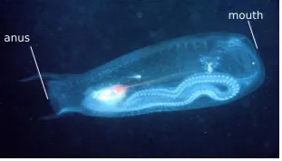
(b) A solitary salp, typical body length>10mm,
[image:2.595.314.470.131.220.2]<100mm ([5]).‘Thetys vagina Salp, Solitary Phase‘, Lovell and Libby Langstroth, 2005, Li-censed under CC BY-NO-SA 3.0 via California Academy of Sciences. Original image edited by addition of annotations.
Figure 1: Photographs of salps in their two life phases.
Most robots depend on well established sources of power that limit the range of operation of the robot either by tethered operation, for example pneumatic or hydraulic actuation driven by pumps too large to carry on-board [6], or the requirement to return intermittently to a base-station in the case of robots with re-chargeable batteries [7]. Recent soft robotics research has shown actuation mechanisms driven by environmen-tal stimuli, for example chemical gradients [8] or phototaxis [9]. However, these robots do not store energy for use in lean times, nor do they optimise the way in which this energy is used. The foraging behaviour of natural organisms presents a more promising solution for powering energy autonomous robots. Robots that emulate this behaviour to provide long term energy autonomy in remote environments using scavenged envi-ronmental energy include those which use photovoltaic cells ([10],[11]), kinetic energy from the wind or tide ([12],[13]), underwater thermal gradients [14] and fermentation [15] and combustion [16] of biomatter.
oxygen O2
water H2O organic
material
H2O
oxidised material, carbon dioxide CO2
O2
e-
e-CO2 organic material
H+
H+
e-anode cathode
[image:3.595.217.376.130.284.2]electrical load
Figure 2: Diagram showing principle of operation of an MFC. Organic matter is oxi-dised at the anode electrode. Standard reduction and oxidation (redox) potentials gen-erated by oxidation of organic carbohydrates at the anode and reduction of cations at the cathode result in a potential difference across the MFC and the flow of current when the electrodes are connected by a resistive load.
Microbial fuel cells (MFCs), which are used to power robots such as Gastrobot [17] and the EcoBot robot series [18] exploit the metabolism of microbes to break down organic biomass and convert it into electricity. The configuration of an MFC comprises two electrodes which are separated electrically, but allow the intermediate transport of ions (Figure 2). Previous work has demonstrated the use of naturally occurring substrates such as seawater [19], marine and freshwater sediment [20] and waste water [21] as an energy source for MFCs, showing their suitability for powering robots in many different aquatic environments.
Until now the operation of these robots has been limited to within a controlled en-vironment by the use of wheeled locomotion and complex mechanisms to feed from specifically designed dispensers [18]. Additionally, the conductivity of the fluid sub-strates fed to MFCs can result in the unwanted connection of electrodes in contact with the fluid, limiting their use to power aquatic robots. In contrast to the rigid mecha-nisms previously used, we demonstrate that by using a soft structure, a simple, low cost mechanism is achieved that allows the connections of multiple MFCs in series in fluid environments.
ar-tificial muscle actuator in the design of a soft robotic tadpole [23]. Arar-tificial muscles such as IPMC and shape memory alloy (SMA) are a complementary technology for use with an MFC power source due to low drive voltages (1-3V) and high biocompat-ibility [24]. IPMCs create a bending actuation due to the migration of mobile cations and water molecules. Shape memory alloys (SMA) exhibit thermal transition from the austenitic phase, where the material has a highly elastic structure and assumes its permanent shape, to the martensitic phase where it can be deformed into a temporary shape by application of external stress [25]. As preliminary study we evaluate the me-chanical output of these soft thermally and ionically active actuators, driven from the energy harvested from the MFC artificial stomach. This research contrasts with previ-ous work on MFC-powered robots by showing the potential for total energy autonomy using a single MFC.
1.1
Energy Cycle of the Foraging Behaviour
Ener
gy
Time Ehi
Elo
Charge
Open Mouth
Close Mouth
Charge
Work output
Eaction
[image:4.595.199.397.321.457.2]Discharge
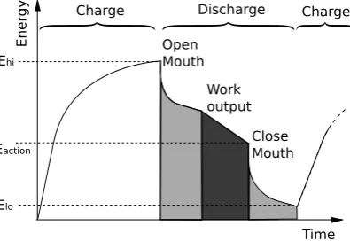
Figure 3: Graph showing the two-phase (charge and discharge) anticipated behavioural cycle of a foraging robot. The robot charges (charge phase is shown in white) until the energy reaches threshold Ehi. Then it discharges (the discharge phase is shown in grey, with light grey representing the critical operations for energy sustenance and dark grey representing use of the net energy of the system for useful work). When its energy level falls to a low state, Elo, all energy discharge is halted, allowing charge accumulation to begin again as the organic material is digested. Any surplus energy can be used for goal-directed operations such as sensing and communication, controlled by intermediate thresholds, for example Eaction.
The simple behaviour cycle for a soft foraging robot with an MFC stomach is shown in Figure 3. The anticipated operation of the robot during the discharge is to open its mouth, move, and then close its mouth, having ingested a fresh batch of feedstock from which it harvests energy during the charge cycle.
We firstly describe the design of the device used in the study (Section 2). Three areas are evaluated; the power production of the MFC, the energy harvested from the MFC and the use of this energy to drive conventional motors and electroactive soft actuators. The experimental method for these investigations is set out in Section 3, followed by a discussion of the results in Section 4. Finally we present the conclusions of the study (Section 5).
2
Foraging Robot Design
anode
-fluid flow through MFC
travel of MFC electrical
load
air
PEM cathode +
(a) MFC with the cathode electrically isolated from the fluid surrounding the MFC by an air chamber. The an-ode is electrically connected to the surrounding fluid.
anode
-fluid flow through MFC
travel of MFC electrical
load
air
PEM cathode +
(b) MFC with a mouth mechanism at each end of the anode chamber and with the cathode electrically iso-lated from the fluid surrounding the MFC by an air chamber. When the mouth is open, as shown, the an-ode is electrically connected to the fluid surrounding the MFC.
anode
-travel of MFC electrical
load
air
PEM cathode +
[image:5.595.212.384.456.541.2](c) MFC with a mouth mechanism at each end of the anode chamber and with the cathode electrically iso-lated from the fluid surrounding the MFC by an air chamber. When the mouth is closed, as shown, the an-ode is electrically isolated from the fluid surrounding the MFC.
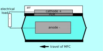
Figure 4: Schematic showing 2D cross-section of an MFC in which anolyte is replen-ished by inflow and outflow of fluid through orifices at each of the anode chamber. The surrounding fluid in which the MFC is submerged is shown as a shaded area around the MFC. The figure is not to scale.
cath-ode exposed to the overlying air (Figure 4(a)). However, this prevents the connection of multiple MFCs electronically in series, a widely used strategy for voltage multi-plication, due to the unwanted electrical connection by the surrounding fluid. By im-plementing a mouth-like open-and-close mechanism (Figure 4(b)) the individual MFC anodes are isolated when the opening is closed (Figure 4(c)), allowing operation of the MFC-powered robots either as individual units or in series electrical configuration.
2.1
Design of the Mouth
mouth closed, isolating MFC anode chamber from surrounding fluid
70mm 60mm
(a) Robot with mouth closed, isolating the anode from the surrounding fluid.
mouth open, allowing inflow and outflow of fluid to MFC MFC cathode
chamber
192mm
MFC anode chamber
[image:6.595.205.406.467.603.2](b) Robot with mouth open, allowing fluid inflow and outflow to the anode chamber.
Figure 5: CAD drawing showing key components of the design for a robot with MFC stomach fed by a soft, bio-inspired mouth mechanism, which is shaded in grey. The approximate water level is indicted by the dotted lines in each figure. The cathode chamber isolates the cathode electrode from the surrounding fluid and exposes it to the overlying air.
The robotic MFC floated at the water surface. The mouth mechanism was inspired by the suction feeding of vertebrate fish, which involves expansion of the intra-oral cavity in order to transport food-rich fluid into their mouths [26]. Origami folding of a single soft acetate membrane (thickness = 240µm approx.) (Figure 5) was used to open the mouth, drawing in the surrounding fluid with suspended particulate matter (Figure 5(b)), and close the mouth, raising the lips of the mouth above the water level (Figure 5(a)). Using this low cost (<£0.5), simple, lightweight, mechanism, the MFC can be fed directly from its fluid surroundings. In contrast to the use of rigid compo-nents, use of a soft membrane allowed electrical isolation of the anode chamber from the surrounding fluid when the mouth is closed, without the need for joints or seals. This isolation permits voltage multiplication by series connection of individuals in a configuration, resembling a chain of connected salps.
For repeatability in testing the novel mechanism, the corner folds of the soft mem-brane were gear coupled to a single central motor drive using rigid plastic components. The MFC cathode chambers were produced from acrylic to replicate the design of an analytical style MFC, enabling direct comparison of the performance of the novel feed-ing mechanism with this well-established design. For example, recent work has shown 5J per batch of food administered can be generated using this type of analytical-style MFC [27].
anode side cathode side stainless steel mesh
stainless steel wire 10mm
(a) Photograph of MFC in open circuit mode, meaning there is no electrical connection be-tween anode and cathode elec-trodes.
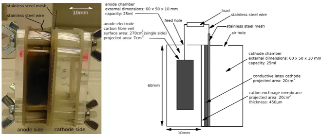
10mm 60mm anode chamber
external dimensions: 60 x 50 x 10 mm capacity: 25ml
anode electrode carbon fibre veil
surface area: 270cm (single side) projected area: 7cm
2 2
load
stainless steel mesh feed hole
air hole
cathode chamber
external dimensions: 60 x 50 x 10 mm capacity: 25ml
-cation exchnage membrane projected area: 20cm thickness: 450µm
2 conductive latex cathode projected area: 20cm 2 stainless steel wire
[image:7.595.131.461.368.506.2](b) Schematic detailing the components of the MFCs used in this study. A conductive latex cathode was used to maintain a continu-ous redox reaction without the need to hydrate the cathode electrode. A polyurethane-based rubber coating (Plasti-Dip, Petersfield UK) was mixed with white spirit and micronised graphite powder in the mass ratio 2:3:1, using a method derived from [28] and painted onto the air side of the membrane. The MFC is configured with an electrical load connecting the anode and cathode electrodes.
Figure 6: An analytical style MFC used as the control experiment in this study and, therefore, on which the design of the MFC with mouth was based.
2.2
The Energy Balance
To achieve the energy autonomy, it was critical that the feeding mechanism could be actuated without energy consumption in excess the energy budget defined by the MFC stomach stomach used to power it.
whereEmf c is the energy generated by the MFC andWbody is the mechanical work done by the body, including supply of energy to the MFC. Additionally, the electrical energy harvested,Eharvested, and the electrical energy consumed, Ebody, depend on the efficiency of the energy harvesting hardware and motors, respectively. Therefore we can re-define Equation (1) as
Eharvested>Ebody (2)
The work,Wbody(Table 1), to drive the mouth mechanism, was evaluated experimen-tally by using a DC motor (AMAX12, Maxon) to drive the central input gear. The work done was found by integrating the powerPmechover the opening and closing strokes respectively using the product of the motor torqueτand motor angular velocityω.
Wbody =
Z tf
ti
Pmechdt=ω
Z tf
ti
τ dt (3)
A potentiostat (Hokuto Denko) was used to set a voltage and measure the current drawn by the motor at that voltage. The torque was derived from the current drawn by the motor.
Based on previous work using analytical style MFCs (Figure 6),Emf ccan be esti-mated as 5J [27].Wbodycan be estimated asWopen+Wclose(Table 1). This suggests that Equation (1) may be satisfied, showing the potential of the robot for energy au-tonomous operation. However, the energy consumed in actuating the motors,Ebody, due to the efficiency the DC motor used, means that Equation (2) cannot be satisfied. Therefore, the next stage is to firstly, evaluate the energy output by an MFC with the novel design for a soft bio-inspired mouth, in comparison to a conventional analytical style MFC.
Henceforth, we term the MFC with the mouth the ‘artificial stomach’ to distinguish it from the conventional analytical style MFC, termed the ‘control MFC’. Based on this performance verification, suitable actuators and energy harvesting hardware must be sourced to produce a design for an energy autonomous robot, powered by the MFC stomach, by satisfying Equation (2).
Table 1: The electrical energy consumed, Ebody = Eopen +Eclose, to supply the mechanical workWbody = Wopen+Wclose, to actuate the mouth, and the resulting first law thermodynamic efficiencyη.
Wbody(J) Ebody, (J) η(%)
Open 0.04 1.4 2.86
Close 0.16 4.19 3.82
3
Experimental Method
3.1
Power Production From MFCs
Two identical analytical style MFCs were set up (Table 2). One was converted to the artificial stomach with the soft mouth and the other was used as the control. A servo motor (Carson) was initially used to drive the feeding actuation. An Uno micro-controller board (Arduino) was used to control actuations of the robotic MFC, using
manual input switches. The energy required by this system to actuate the mouth and transport the robot was 345.37J.
mouth motor(mouth)
MFC submerged
pulley
floats motor (transport)
with potentiometer for position feedback
[image:9.595.165.432.168.339.2]microcontroller
Figure 7: Photograph of the artificial organism in a container of fluid
The foraging robot which was partially submerged in a container of 10L of fluid (Figure 7) of the same composition as the anolyte (Table 2).
The composition of the fluid was chosen to replicate that used in previous work [27] demonstrating power production from MFCs of this type.
Table 2: Experimental method using two identical analytical style MFCs. A single batch feed involved removing 25ml anolyte using a syringe and replacing it with 25ml of 5mM acetate solution, mixed with 0.2% tryptone, 0.1% yeast extract.
Day Operation
0 Two analytical style MFCs inoculated: sewage sludge (Wessex Water, Saltford UK) mixed with 2.5% nutrient broth. 10kΩload.
Data logger: LXI data acquisition/switch unit (Agilent Technologies).
0 - 12 Every 2nd day: 5ml anolyte removed, replaced with 5ml stock solution (25mM acetate solution, mixed with 1% tryptone, 0.5% yeast extract).
12 Batch 1, 10kΩload applied
20 Batch 2, 1kΩload applied (optimum load for MFCs of this type, [27] to imitate fixed load of EH4295 Micropower Step Up Low Voltage Booster)
33 Batch 3, 1kΩload applied
45 One of the two analytical style MFCs dismantled. Anode, cathode and cation exchange membrane converted to MFC with mouth.
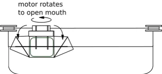
motor rotates to open mouth
(a) Mouth opens (17s) then remains open for further 3 minutes.
tensioned string motor rotates to
drive linear travel
(b) Artificial stomach with mouth transported 20cm linearly at a velocity of 2.5ms−1 across container of fluid, with mouth open, by rotation of second servo mo-tor fixed to periphery of container. Rotary potentiome-ter coupled to second servo motor for position feedback to microcontroller. The mouth then remains open for a further 1 minute. Direction of travel alternated with each feed.
motor rotates to close mouth
[image:10.595.222.383.659.751.2](c) Mouth closes (17s)
Figure 8: Operations used to feed the artificial stomach. The surrounding fluid in the container was replenished prior to each feed.
The artificial stomach was also fed without transporting it across the container using the rotation of a motor as shown in Figure 8(b) over 2 batches (19 and 20) to evaluate the necessity to travel across the container as a feeding operation.
3.2
Harvesting Energy from MFCs
Energy harvesting circuitry was sourced to store the low output voltage of the MFC-stomach at a boosted voltage for use in feeding an energy autonomous, soft robot. DC motors were sourced to drive the actuation of the soft robot with sufficient efficiency
thatEbody<Eharvested, satisfying Equation (2) and showing the potential of the robot
for energetic autonomy.
While a number of examples of energy harvesting from MFCs using ultra-low volt-age input circuits are demonstrated in the literature ([29], [30], [31]), the range of en-ergy harvesting hardware available to MFC technology remains severely limited [32]. As it stands, the current state of the art in commercially available low power voltage step-up technology is represented by the EH4295 inductor-based voltage booster (Ad-vanced Linear Devices Inc). The device outputs AC voltage with a gain between 7 and 10 and has a lower input voltage threshold of 60mV. It has a nominal impedance of 950
Ω. This voltage booster was used to increase the low voltage output of the MFC and an energy harvesting board (EH300, Advanced Linear Devices Inc) was used to rectify the AC output of the voltage booster to a DC voltage, enabling the charge of a storage capacitor (Section 3.2).
MFC
boostervoltage(EH4295)
capacitor (0.33F) energy
harvester (E300)
[image:11.595.126.472.401.445.2]V
MFCV
ACV
DCFigure 9: Block diagram of hardware
3.3
Powering Actuators Using Harvested Energy
3.3.1 Powering DC motors
To demonstrate the potential of the robot for energy autonomous operation, high effi-ciency DC motors and gearheads (RE 10 & GP 10 K (Maxon), 16C18, & M915L61(Portescap)) were selected to actuate a replicate of the foraging robot, identical to the design shown in Figure 5, which contained no microbes. The motors were powered by the discharge of 3 x 1F super- capacitors (PowerStor, B series) charged in series to 4.0V (2.64J); the mean recorded energy harvested from the MFC stomach, at this time. Manual switch-ing was used to control the supply of charge to the motors.
3.3.2 Powering IPMC Artificial Muscle
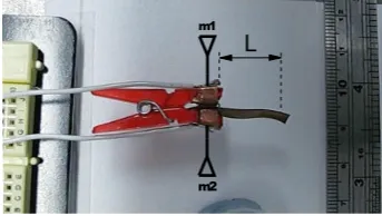
polarities at a frequency of 1Hz. A micro-controller (PIC12LF1822, Microchip) was used to control the switching and was powered in parallel with the IPMC from the discharge of the capacitor. The IPMC strip of length 2.5cm and width 1cm, made from Nafion 117(DuPont), was electroless plated with gold electrodes using the the impregnation reduction fabrication method described in [33]. The Nafion 117 layer had a thickness of 180 microns and the electrode thickness was estimated as 10 microns based on previous work in [34]. The IPMC was fixed with a copper connection at one end. Cantilever actuation of a point at L=1.49cm (Figure 10(a)) from the fixed end was measured using a laser displacement sensor (Keyence LK-G150).
Vs s Q 4 Q 5 M m 2 L Q4 M m2 Vs s Q
4 Q5
M m 2 6 5 2 4 3 Vss Q2 m1
(a) Experimental setup for evaluation of IPMC actu-ator, viewed from above. L = length of fixed end to point measured by laser displacement sensor. m1 and m2 are connected to the driving electrical circuit shown in Figure 10(b)
OUT 7 MIN 6 CI1 5 NQ 2 CLR 4 CI2 3 Vdd Vss N2 N1 N3 N4 Vdd Vss C1 0.33F supply m2 m1 d1 d3 d2 d4
[image:12.595.211.383.247.344.2](b) Schematic of electrical circuit driving IPMC actuation. The h-bridge comprised of 4 N-channel, enhancement mode MOSFETs (N1-4), switched by digital output of microcontroller (d1-4)
Figure 10: Experimental set-up for IPMC actuation.
3.3.3 Powering SMA Artificial Muscle
A mass of 3g was suspended vertically by a helical shape memory wire actuator (BioMetal helix, Toki Corp.) of wire diameter (0.15mm) and spring diameter (0.62 mm) and an equilibrium length of 21.6mm. The 3 x 1F super- capacitors charged in series to 5.5V (5J) were discharged directly to the SMA actuator (Figure 16).
m
m
martensite austenite
SMA
Vdd
Vss C1
0.33F supply 3
4
Vdd
Vss C1
0.33F supply Vdd
Vss N2
N1 N3
N4
Vdd
Vss C1
0.33F supply
[image:13.595.217.373.128.238.2]m2 m1
Figure 11: Schematic of SMA actuation driven from direct discharge of supply capac-itor C1.
4
Results and Discussion
4.1
Power Production from MFCs
Prior to converting one of the two analytical style MFCs to the artificial stomach design, similar performance (peak power = 18.0µW and 21.45µW respectively, under 1kΩ, mean of batches 2-3) was shown by the MFCs.)
Following conversion, continued similarity was shown between the performance of the artificial stomach and the control MFC (10.40 J energy per batch, peak power = 22.86µW, and 10.57J energy per batch, peak power of 24.50µW, respectively, aver-aged over 6 batches). This demonstrated that the novel mode of feeding was effective and that MFC performance improved temporally. However, difference between the cy-cles of the two MFC types can be seen clearly in Figure 12. This may indicate that the difference in feeding mode can impact the peak power output from the MFC.
120 125 130 135 140
120
time (days) 0
5 10 15 20 25 30
p
o
w
e
r
(
¹
W
)
stomach control
[image:13.595.206.400.491.636.2]4.2
Harvesting Energy from MFCs
230 235 240 245 250
228
time (days) 0.00
0.05 0.10 0.15 0.20
voltage MFC (V)
voltage MFC
0.0 0.5 1.0 1.5 2.0 2.5 3.0 3.5 4.0 4.5
voltage capacitor (V)
[image:14.595.202.399.169.309.2]voltage capacitor
Figure 13: Voltage output from the artificial stomach to the input of the boost converter (load 950Ω), and the voltage of storage capacitor, charged by the rectified output of the boost converter. Two batches are shown as an example: batches 17 and 18 (beginning day 227 and 243 respectively)
The voltage output of the MFC, when connected to the boost converter and stepped up to the DC-regulated output voltage of the boost converter, charged the 0.33F ca-pacitor connected to the output of the boost converter, as shown in Figure 13. The capacitor was charged to approximately 2.86 J of stored energy per batch (average of three batches) showing an average energy conversion efficiency of 30%. No significant difference in power output was observed when the artificial stomach was not trans-ported across the container of fluid in between opening and closing the mouth (2.87 J of stored energy per batch, average energy conversion efficiency of 29% (average of two batches). This negative result is interesting as it shows that the only actuation re-quired to replenish the contents of the MFC stomach is to open and close the mouth. Therefore, the energy production required of the MFC to achieve energy autonomy is less than initially expected as it does not need to power transport in addition to the mouth.
4.3
Powering Actuators Using Harvested Energy
4.3.1 Powering DC motors
The energy consumed,Ebody, to actuate the mouth and transport the robot was 1.81J, which satisfied the Equation (2) where the input energy,Eharvested, was 2.64J.
0 5 10 15 20 25 30 35
time (S)
0 1 2 3 4 5 6
voltage (V)
feed motor
0 5 10 15 20 25 30 35
time (S)
0 1 2 3 4 5 6
voltage (V)
travel motor
mouth
open mouthclose
linear travel
0 5 10 15 20 25 30 35
time (S)
0 1 2 3 4 5 6
voltage (V)
[image:15.595.193.398.126.425.2]capacitor
Figure 14: Direct discharge of 0.33 F capacitor charged to 4.0V to two DC motors to drive feeding and travel actuation respectively via an externally powered switching circuit. The voltage of the capacitor (top), and motors that drive the mouth (middle) and the transportation (bottom) are shown.
4.3.2 Powering IPMC Artificial Muscle
0 10 20 30 40 50 time (s)
4 2 0 2 4 6
voltage (V)
supply voltage IPMC voltage
1.0 0.5 0.0 0.5 1.0 1.5
Displacement (mm)
IPMC displacement
(a) Results from start of experiment to time = 52s
0 2 4 6 8 10
time (s) 4
2 0 2 4 6
voltage (V)
supply voltage IPMC voltage
1.0 0.5 0.0 0.5 1.0 1.5
Displacement (mm)
IPMC displacement
[image:16.595.185.410.127.509.2](b) Results from start of experiment to time = 10s
Figure 15: The supply voltage from the capacitor, the voltage across of the IPMC actuator and the cantilever displacement, during discharge of 0.33F capacitor, charged to 5.5V into IPMC artificial muscle, via a simultaneously power switching circuit, with a switching frequency of 1 Hz.
The bending moment,M, generated by the first actuation of the IPMC, was found byM = 2yIEL2 as 701µNm , where y is the deflection of a point at length,L, from the fixed end of the IPMC and I andE are, respectively, the equivalent moment of inertia and Young’s modulus of the IPMC. The energy consumed from the capacitor per stroke, Eelec = 12CV
2
n−1 − 1
2CV
2
n, where Vn−1 andVn are the voltage of the capacitor of size C prior to and following actuation, decreased from 182mJ to 2mJ over 104 strokes. This showed that energetic IPMC oscillation can be driven from the typical energy output of an MFC. This may have application in future development of an MFC-powered soft robot.
4.3.3 Powering SMA Artificial Muscle
An instantaneous drop in voltage of the supply capacitor (5.5V to 4.0V) indicated the relatively large initial current drawn by the SMA actuator. The SMA contracted to a length of 17.8mm due to the charge from the capacitor Figure 16(a) with a peak force,F= 29mN. The actuator reaches its fully contracted state within 500ms (Fig-ure 16(b)).
0 5 10 15 20 25 30 35 40
time (s) 0.5 0.0 0.5 1.0 1.5 2.0 2.5 3.0 3.5 4.0 voltage (V)
capacitor voltage SMA voltage
0.5 0.0 0.5 1.0 1.5 2.0 2.5 3.0 3.5 4.0 Displacement (mm) SMA displacement
(a) Results from start of experiment to time = 52s
0.0 0.5 1.0 1.5 2.0
time (s) 0.5 0.0 0.5 1.0 1.5 2.0 2.5 3.0 3.5 4.0 voltage (V)
capacitor voltage SMA voltage
0.5 0.0 0.5 1.0 1.5 2.0 2.5 3.0 3.5 4.0 Displacement (mm) SMA displacement
[image:17.595.328.490.227.352.2](b) Results from start of experiment to time = 2s
Figure 16: The supply voltage from the capacitor, the voltage across of the SMA actu-ator and the displacement of the suspended mass during discharge of 0.33F capacitor, charged to 5.5V into SMA artificial muscle.
During the initial contraction, the first law thermodynamic efficiencyηwas found
to be 0.2% byη = Wmech
Eelec = Rt
0F vdt 1
2CVn2−1−12CVn2
whereWmech =
Rt
0F vdt,F is axial
forcevis linear velocity, andEelecis the energy consumed from the capacitor. The force and displacement output may be employed in the design of a robot combining the advantageous characteristics of both soft robotics and MFC power, however these benefits may come at the price of reduced thermodynamic efficiency.
5
Conclusion
work, may be instrumental in improving the real world survivability of the design of the robot, by replacing the complex, multicomponent, rigid actuators. However, there is a likely trade-off between mechanical robustness and thermodynamic efficiency, as shown by the lower efficiency operation of the IPMC actuator in this study (0.2% com-pared to 2.86-3.83% (DC motor)). High efficiency, low power control is a current them of our work towards achieving full energetic autonomy of the foraging soft robot. Ad-ditionally, our future work will investigate the use of a soft mouth to feed a totally soft robot. This work makes a significant contribution to soft and MFC-powered robotics, by their combined use in a completely novel aquatic robot.
This work was supported by the Engineering and Physical Sciences Research Coun-cil (EPSRC) [grant number EP/I032533/1].Jonathan Rossiter is EPSRC Fellow (grant number EP/M020460/1) and also supported by the RoboSoft Coordination Action on Soft Robotics (FP7) Ioannis Ieropoulos is an EPSRC Career Acceleration Fellow (grant numbers EP/I004653/1 and EP/L002132/1).
1Dept. of Engineering Mathematics, University of Bristol, Bristol, UK
2Bristol BioEnergy Centre, University of the West of England, Bristol, UK
3Bristol Robotics Laboratory, Bristol, UK
References
[1] C Laschi, B Mazzolai, V Mattoli, M Cianchetti, and P Dario. Design of a biomimetic robotic octopus arm.Bioinspiration & biomimetics, 4(1), 2009. [2] R F Shepherd, F Ilievski, W Choi, S a. Morin, a. a. Stokes, a. D Mazzeo, X Chen,
M Wang, and G M Whitesides. From the Cover: Multigait soft robot.Proceedings of the National Academy of Sciences, 108(51):20400–20403, 2011.
[3] David McFarland and Emmet Spier. Basic Cycles, Utility and Optimism in Self-Sufficient Robots.Robotics and Autonomous Systems, 20:179–190, 1997. [4] G R Harbison and R W Gilmer. The feeding rates of the pelagic tunicate, Pegea
confoederata and two other salps. Limnology and Oceanography, 21:517–528, 1976.
[5] Sunwoo Kim, Jung-Hye Won, and Chang-Bae Kim. Taxonomic Study of Genus Cyclosalpa (Thaliacea: Salpida: Salpidae) from Korea.Animal Systematics, Evo-lution and Diversity, 28(4):261–268, 2012.
[6] Kurt S Aschenbeck, Nicole I Kern, Richard J Bachmann, and Roger D Quinn. Design of a quadruped robot driven by air muscles. Proceedings of the First IEEE/RAS-EMBS International Conference on Biomedical Robotics and Biomechatronics, 2006, BioRob 2006, 2006:875–880, 2006.
[7] Von Howard Ebron, Zhiwei Yang, Daniel J Seyer, Mikhail E Kozlov, Jiyoung Oh, Hui Xie, Joselito Razal, Lee J Hall, John P Ferraris, Alan G Macdiarmid, and Ray H Baughman. Fuel-powered artificial muscles. Science (New York, N.Y.), 311(5767):1580–3, 2006.
[8] Martin Hanczyc. Droplets: Unconventional Protocell Model with Life-Like Dy-namics and Room to Grow.Life, 4(4):1038–1049, 2014.
[9] M P M Dicker, J M Rossiter, I P Bond, and P M Weaver. Biomimetic photo-actuation: sensing, control and actuation in sun-tracking plants.Bioinspiration & biomimetics, 9(3):36015, 2014.
[10] L. Ray, A. Price, A. Streeter, D. Denton, and J.H. Lever. The Design of a Mobile Robot for Instrument Network Deployment in Antarctica. Proceedings of the 2005 IEEE International Conference on Robotics and Automation, 34(4):2111– 2116, 2005.
[11] Mars Exploration Rover Landings Press Kit. Technical Report January, NASA, 2004.
[12] G A Hajos, J A Jones, A Behar, M Dodd, Jack Jones, Aerospace Engineer, Mis-sions Branch, Senior Principal Engineer, Advanced Thermal, Mobility Technolo-gies, Senior Technical Staff, and Robotic Vehicles Group. An Overview of Wind-Driven Rovers for Planetary Exploration. pages 1–13, 1998.
[13] Etienne Gernez, Cesar Minoru Harada, Rik Bootsman, Zenon Chaczko, Gabriella Levine, and Peter Keen. Protei open source sailing drones: A platform for edu-cation in ocean exploration and conservation. 2012 International Conference on Information Technology Based Higher Education and Training (ITHET), pages 1–7, 2012.
[14] R.E. Davis, C.C. Eriksen, and C.P. Jones. Autonomous buoyancy-driven under-water gliders. In Gwyn Griff, editor,The Technology and Applications of Au-tonomous Underwater Vehicles, pages 37–58. Taylor and Francis, London, 2002. [15] John Greenman, Owen Holland, Ian Kelly, Kevin Kendall, David McFarland, and Chris Melhuish. Towards robot autonomy in the natural world: a robot in predator’s clothing.Mechatronics, 13(3):195–228, 2003.
[16] Brief Project Overview Eatr : Energetically Autonomous Tactical Robot. Techni-cal report, DARPA.
[17] Stuart Wilkinson. “ Gastrobots ”— Benefits and Challenges of Microbial Fuel Cells in Food Powered Robot Applications.Autonomous Robots, 9:99–111, 2000. [18] Ioannis Ieropoulos, John Greenman, Chris Melhuish, and Ian Horsfield. EcoBot-III : a robot with guts. InProceedings of the Alife 7 Conference, pages 733–740, 2010.
[19] Clare E Reimers, Hilmar A Stecher Iii, John C Westall, Yvan Alleau, Kate A Howell, Leslie Soule, Helen K White, and Peter R Girguis. Substrate Degra-dation Kinetics , Microbial Diversity , and Current Efficiency of Microbial Fuel Cells Supplied with Marine Plankton Substrate Degradation Kinetics , Microbial Diversity , and Current Efficiency of Microbial Fuel Cells Supplied with Marine.
Applied and Environmental Microbiology, 2007.
[20] Daniel a. Lowy and Leonard M Tender. Harvesting energy from the marine sedi-ment–water interface.Journal of Power Sources, 185(1):70–75, oct 2008. [21] P. Aelterman, K. Rabaey, P. Clauwaert, and W. Verstraete. Microbial fuel cells
[22] Ioannis Ieropoulos, Iain Anderson, Todd Gisby, Cheng Hung Wang, and Jonathan Rossiter. Microbial-powered artificial muscles for autonomous robots. InTaros Autonomous Robotic Systems, number September, pages 209–216, 2008. [23] Ieropoulos I Philamore H, Rossiter J. An Energetically-Autonomous Robotic
Tadpole with Single Membrane Stomach and Tail. InProc Biomimetic and Bio-hybrid Systems, 4th international conference, Living Machines, LNAI 9222, pages 366–378, 2015.
[24] Mohsen Shahinpoor and Kwang J Kim. Ionic polymer–metal composites: IV. Industrial and medical applications. Smart Materials and Structures, 14(1):197– 214, 2004.
[25] Andreas Lendlein and Steffen Kelch. Shape-Memory Polymers. Angew. Chem. Int. Ed., 41(12):2034–2057, 2002.
[26] Mark W Westneat. Skull biomechanics and suction feeding in fishes. In George V Lauder Robert E. Shadwick, editor,Fish Physiology: Fish Biomechanics, pages 29–69. Academic Press, 2006.
[27] Hemma Philamore, Jonathan Rossiter, Peter Walters, Jonathan Winfield, and Ioannis Ieropoulos. Cast and 3D printed ion exchange membranes for monolithic microbial fuel cell fabrication.Journal of Power Sources, 289:91–99, 2015. [28] Jonathan Winfield, Lily D Chambers, Andrew Stinchcombe, and Jonathan
Rossiter. The power of glove : Soft microbial fuel cell for low-power electronics.
Journal of Power Sources, 249:327–332, 2014.
[29] Deukhyoun Heo. Batteryless , Wireless Sensor Powered by a Sediment Microbial Fuel Cell.Environmental science & technology, 42(22):8591–8596, 2008. [30] Daxing Zhang, Fan Yang, Tsutomu Shimotori, Kuang Ching Wang, and Yong
Huang. Performance evaluation of power management systems in microbial fuel cell-based energy harvesting applications for driving small electronic devices.
Journal of Power Sources, 217:65–71, 2012.
[31] Nicolas Degrenne, Bruno Allard, Francois Buret, Florent Morel, Salah-Eddine Adami, and Denis Labrousse. Comparison of 3 self-starting step-up DC:DC con-verter topologies for harvesting energy from low-voltage and low-power micro-bial fuel cells. Proceedings of the 2011 14th European Conference on Power Electronics and Applications, pages 1–10, 2011.
[32] Andrew Meehan, Hongwei Gao, Senior Member, and Zbigniew Lewandowski. Energy Harvesting With Microbial Fuel Cell and Power Management System.
IEEE Transactions on Power Electronics, 26(1):176–181, 2011.
[33] Naoko Fujiwara, Kinji Asaka, Yasuo Nishimura, Keisuke Oguro, and Eiichi Torikai. Preparation of gold-solid polymer electrolyte composites as electric stimuli-responsive materials.Chemistry of Materials, 12(6):1750–1754, 2000. [34] Mohsen Shahinpoor and Kwang J Kim. Ionic polymer – metal composites : I .,
volume 819. 2001.
[35] Peter Aelterman, Korneel Rabaey, Hai The Pham, Nico Boon, and Willy Ver-straete. Continuous Electricity Generation at High Voltages and Currents Using Stacked Microbial Fuel Cells. Environmental Science & Technology, 40(10):3388–3394, 2006.