© 2019, IRJET | Impact Factor value: 7.211 | ISO 9001:2008 Certified Journal | Page 1563
IMPLEMENTATION OF DYNAMIC INTERNETWORKING IN THE REAL
WORLD IT DOMAIN
Hemanth SM
1, Yathish Babu MP
2, Dr. Mary Cherian
3, Mr. Pradeep Sagar BL
41
Technical student, Dept of Computer Science Engineering, Dr.AIT, Karnataka 560056, India
2Technical student, Dept of Computer Science Engineering, Dr.AIT, Karnataka 560056, India
3
Proffesor, Dept of Computer Science Engineering, Dr.AIT, Karnataka 560056, India
4Technical Manager, Cisco BU, Inflow Technologies Pvt Ltd, Bengaluru, Karnataka, India
---***---Abstract -
This project is aimed to measure the ease use of a network infrastructure we design, build and operate for an organization. The project also aims to find out the general aspects of computer networking. For example: the devices, the physical or logical aspects of a computer network, as well as network topologies. This study briefly discusses the architecture of an enterprise network. It examines the barriers to planning, designing and implementing an enterprise network. This study also covers the methods to implement enterprise level networks. A basic router configuration is used for covering the Routing technologies which route data between branches using protocols such as Routing Information Protocol (RIP), Open Shortest Path First (OSPF) and Enhanced Interior Gateway Routing Protocol (EIGRP). A private address 172.16.0.0 network is sub netted for the efficient use of addresses. Dynamic Host Configuration Protocol (DHCP) is configured on the server to automatically assign IP addresses to hosts. Authentication is enabled using Challenge Handshake Authentication Protocol (CHAP). Access Control List (ACL) and Domain Name System (DNS) are also configured in the topology.Key Words: Network infrastructure, Organization, Enterprise, Protocol, Address.
1. INTRODUCTION
Enterprise network implementation is totally based on network. Enterprises and large organizations use IT to make reliable and secure communication including secure transfer of documents, files etc. In an enterprise, departments are separated for good results which is why we included this characteristic in our project. This type of network avoids the unauthorized access, it authenticates the authorized users or hosts. This is done by ACLs as they filter traffic and provide security to the network. The fundamental purpose of designing this scenario is to provide security in your network to secure your private data and make a reliable and excellent communication in a WAN connection and reduce the organization dependency on floppy disks etc. Organizations that share data through the use of floppy disks, DVDS, CDs etc follow a non-efficient or cost-effective method. The issue is that the business by using this method to share data leads to duplication of data which effects the growth of the business. Another major issue is the lack of communication that is all details cannot be conveyed at the required time. The scope of creating company network scenario is to have a secure WAN network for the communication purpose of an enterprise that eradicate data redundancy from the grass root level which shows smooth functioning of a network.
1.1 Objectives
The objective of this project is to help organizations to implement robust networking solution To build a sophisticated networking solution to meet the different organization’s demand To consider right networking components to build network from industry leading vendor Cisco To detail the skill set required to meet the next generation requirement.
1.2 Methodology
The steps used here are
i. Determine Requirements: The first step in deploying the Network Infrastructure is to determine the requirements as determined by the client’s situation. This step involves: Analysing business operations to determine features and functions needed,
© 2019, IRJET | Impact Factor value: 7.211 | ISO 9001:2008 Certified Journal | Page 1564
and operational needs is addressed. The solution consists of the platforms and systems that make up the architecture as well as the features, functions, and applications that provide the services required.iii. Assess Network and Infrastructure Readiness: Network and infrastructure readiness assessment involves the review and audit of all network infrastructure areas that will be affected by the deployment. The assessment is performed at each site where the network solution will be deployed. Items to assess include: Network design (routing and switching network), software, hardware, environment, network links and network services.
iv. Develop a Detailed Design: After developing the site requirements, it is time to develop a detailed design for the system based on the requirements identified. The detailed design will address a wide variety of issues regarding each component that will be implemented.
v. Developing Implementation Plan: Developing an implementation plan involves defining the processes required to carry out the implementation of the system. Among the necessities considered during his step are the following key factors: Accurate scheduling of any site-specific actions needed prior to implementation, equipment delivery and staging, project phases and deadlines, acceptance criteria for each project phase etc.
vi. Stage and Configuring solution: Staging and configuring of the system can help make final installation more efficient. For this step, the following tasks are performed:
Assemble the components that will be installed at each site, perform basic testing of hardware and software and pre-configure the devices.
vii. Install the Solution: Installing the system involves installing and re-configuring the network infrastructure and installing and setting up the system components. After verifying the readiness of the equipment, the following general steps to install the solution is performed: Catalogue and inventory the system components, install the equipment in data racks, complete cabling and other physical connectivity, verify that all units power up correctly and capture installation-specific information.
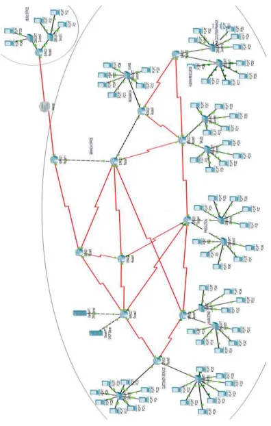
1.3 Creation of the topology
We have created our topology using Cisco Packet Tracer software. We have considered our topology to be in two different regions (branch and head office). We have divided branch office network into seven departments. We have considered routers, switches, computers, DHCP server based on the requirements. Firstly, a private address 172.16.0.0 is sub netted for our topology. The range of address used here are 172.16.0.0 – 172.16.208.0. Dynamic Host Configuration Protocol (DHCP) has been configured on the server to automatically assign IP addresses to the hosts/computers. Routing protocols (RIP, OSPF and EIGRP) are configured on all the routers. Access control lists are configured to filter traffic in the network. There are two types of access lists. Here in our topology we have configured named extended access list. The list does the following:
1. Denies FTP data (port 20) communication from ‘customer service’ to ‘sales.’ 2. Denies ICMP communication from ‘marketing’ to ‘production’.
3. Denies telnet (port 23) communication from ‘research’ to ‘marketing’. 4. Denies IP communication from ‘accounting’ to ‘sales’.
5. Denies HTTP (port 80) communication from ‘production’ to ‘human resource’.
© 2019, IRJET | Impact Factor value: 7.211 | ISO 9001:2008 Certified Journal | Page 1565
2. NETWORK TOPOLOGY
© 2019, IRJET | Impact Factor value: 7.211 | ISO 9001:2008 Certified Journal | Page 1566
3. RESULT
[image:4.595.152.445.154.343.2]3.1 DHCP configuration On PC 4 of ‘Customer service’.
Fig -3.1: DHCP
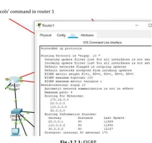
3.2 Routing Protocol:
Result of ‘show Ip protocols’ command in router 1
[image:4.595.138.448.400.691.2]© 2019, IRJET | Impact Factor value: 7.211 | ISO 9001:2008 Certified Journal | Page 1567
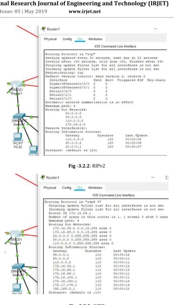
Fig -3.2.2: RIPv2© 2019, IRJET | Impact Factor value: 7.211 | ISO 9001:2008 Certified Journal | Page 1568
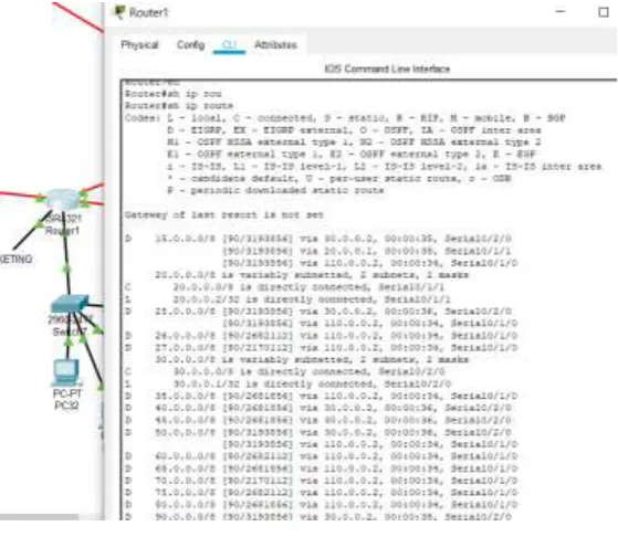
Result of ‘show ip route’ command in router 1 [image:6.595.157.442.215.652.2]Fig -3.2.4: Routing table
© 2019, IRJET | Impact Factor value: 7.211 | ISO 9001:2008 Certified Journal | Page 1569
3.3 Pinging: [image:7.595.130.469.142.334.2]Successful communication from PC 18 ‘marketing’ to another region of topology (head office).
Fig -3.3: Pinging
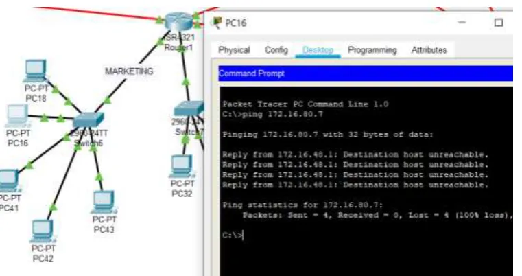
3.4 Access control list:
Successful denial of communication from marketing to production.
[image:7.595.112.493.430.631.2]© 2019, IRJET | Impact Factor value: 7.211 | ISO 9001:2008 Certified Journal | Page 1570
3.5 VLAN Communication: [image:8.595.91.500.141.321.2]Successful communication between PC 12 and PC 66 (Inter-VLAN routing).
Fig -3.5: VLAN Communication
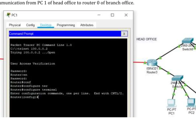
3.6 Telnet:
Successful communication from PC 1 of head office to router 0 of branch office.
Fig -3.6: Telnet
4. CONCLUSION
[image:8.595.98.496.382.624.2]© 2019, IRJET | Impact Factor value: 7.211 | ISO 9001:2008 Certified Journal | Page 1571
REFERENCES
[1] Comer, Douglas (2000). Internetworking with TCP/IP: Principles, Protocols, and Architectures – 4th ed. Upper Saddle River, NJ: Prentice Hall. p. 394. ISBN 0-13-018380-6.
[2] S. Floyd & V. Jacobson, “The Synchronization of Periodic Routing Messages”, April 1994 [3] “PORT NUMBERS”, The Internet Assigned Numbers Authority (IANA), May 2008 [4] “Network Security Basics”, 7 May 2004 by Robyn Aber
[5] IEEE 802.1Q-2011, 1. Overview
[6] IEEE 802.1Q-2011, 1.4 VLAN aims and benefits
[7] RFC 760, DOD Standard Internet Protocol (January 1980)
[8] Internet Protocol-DARPA Internet Program Protocol Specification. September 1981. p. 7. RFC 791. [9] "Net Acuity Edge Offers Hyper-local IP targeting" Retrieved 201112-10.
[10] Groth, David; Toby Skandier (2005). Network+ Study Guide, Fourth Edition. Sybex, Inc. ISBN 0-7821-4406-3.