http://dx.doi.org/10.4236/ijcns.2012.55035 Published Online May 2012 (http://www.SciRP.org/journal/ijcns)
Weighted Sum Rate Maximization in OFDM Based
Cooperative Cognitive Radios:
A Joint Optimization Approach
Pedram Johari, Vahid Tabataba Vakili
Communications Engineering Department, School of Electrical Engineering, Iran University of Science and Technology (IUST), Tehran, Iran
Email: [email protected], [email protected]
Received March 14, 2012; revised April 16, 2012; accepted April 23, 2012
ABSTRACT
Improving utilization of the radio spectrum is the main goal of Cognitive Radio Networks (CRN). Recent studies made use of cooperative relay technology in cognitive networks, to increase transmission diversity gain. In this paper we con-sider an OFDM based cooperative cognitive network with a pair of Source-Destination nodes as the primary user (PU), and a pair of Source-Destination nodes—which is assisted with a relay—as the secondary (cognitive) user (SU). Both primary and secondary users share a same spectrum. In a two hop transmission, the source transmits in the first hop, and the half-duplex relay decodes the message, re-encodes and forwards it to the destination in the second hop on a different subcarrier. The cognitive network obeys an underlay paradigm where the SU is allowed to transmit simultaneously with PU, while its power is limited such that the interference caused for PU does not exceed a defined temperature. Under this constraint, a joint subcarrier pairing and power allocation is proposed for SU to maximize its weighted sum rate. The problem is transformed to a convex optimization problem and solved in the dual domain. Then an algorithm to achieve feasible solutions is used based on the optimization results. Through extensive simulations, we compare the spectrum utilization of the proposed approach with the existing ones, and show that interestingly the proposed method improves the weighted sum rate of SU.
Keywords: Cooperative Cognitive Radio; Underlay Transmission; OFDM; Joint Optimization
1. Introduction
In the era of communications, daily increasing demands for wireless services and its high penetration in routine human activities is overloading the precious radio spec-trum. Beside this bottleneck, and according to spectrum efficiency measurements recently revealed by FCC [1], the inefficient usage of available spectrum in fixed as-signments scenarios causes the effort for more utilizing the scarce spectrum to be the focus of many researches. Emerging Cognitive Radio Networks (CRN)—coined by Joseph Mitola in his Doctoral Dissertation [2]—is be-coming an efficient solution to this problem in recent years. Diverse aspects of CRNs have been studied in many articles since then. A detailed exposition of Cogni-tive Radios (CR) from the signal processing point of view has been presented in [3]. Development of the IEEE 802.22 as the first Cognitive Radio Wireless Regional Area Network Standard is a worldwide effort to embark use of this novel technique [4]. As it is categorized in [5], there are three well known paradigms for unlicensed use of spectrum in CRNs: Interweave, Overlay, and
Under-lay.
Among different system models defined in recent studies, some made use of cooperative relay technology in cognitive networks to increase transmission diversity gain. In [6] a number of cooperative diversity cognitive models are discussed by combining a cognitive radio with the cooperative technique. A brief overview of ap-plications of cooperative cognitive networks is presented in [7]. Also cooperative transmission between secondary nodes to improve spatial diversity and improve spectrum diversity with a focus on the latter one is discussed, and a new MAC protocol is proposed [7].
and the power allocation optimization problem for cogni-tive user and cognicogni-tive relay is considered [9]. A joint subcarrier and power allocation algorithm for coopera-tive multiuser orthogonal frequency division multiplex-ing (OFDM) CR is presented in [10]; where a DF coop-erative strategy is used, and a three-node relay network is simplified to a tow-node network with the equivalent channel gain. In [11] joint relay selection and power al-location is investigated in a CR system to maximize sys-tem throughput by developing an optimal approach. Also a suboptimal approach is proposed which reduces com-plexity while maintaining performance. A relay selection in cooperative cognitive network is proposed in [12], in which a secondary node relays PU information to reduce the power consumption of PU, and simultaneously de-crease interference from primary traffic which exposes spectrum opportunities for secondary system. In [13] a two-user AF relaying cognitive network is considered, and jointly allocation of sensing time and power is de-veloped to maximize throughput of secondary network.
It can be widely seen that novel wireless communica-tions tend to use multi-carrier OFDM method because of its flexibility in resource allocation and the benefits on minimizing the impact of multi-path fading. To be in harmony with this trend, our interest in this study lies on an OFDM-based cooperative cognitive radio network. Among three different paradigms of cognitive radios, we choose underlay transmission where both the primary and cognitive users transmit over a same spectrum. Two pairs of Source-Destination (SD) nodes are considered where one pair is the primary user and the other is the secondary user. Also we assume that the secondary user’s transmission is assisted with a cognitive DF relay node. In underlay scenario, it is assumed that the secon-dary network is aware about channel gains from its transmitters to the PU. SU’s and the relay’s power are limited in this case, because simultaneous transmission with licensed users is available while cognitive transmit-ters (secondary source and the relay) have not violated an interference temperature which is constrained by primary network.
Our goal is to maximize the throughput of secondary network with interference power constraint defined by primary network, and total power constraint of secondary transmitter and the relay. A joint optimization of power allocation and subcarrier pairing for secondary transmit-ter and the DF relay node is developed. We formulate the joint power allocation and subcarrier pairing optimiza-tion problem, and then solve it using continuous relaxa-tion, to reform the problem to dual problem. An algo-rithm to achieve feasible subcarrier pairing and power allocation is proposed based on the solution results. Ex-tensive simulation results show that the proposed algo-rithm almost achieve the optimal weighted sum rate, and
outperform existing methods in secondary throughput improvement.
The rest of this paper is organized as follows. In Sec-tion 2, we define our cooperative cognitive radio network model and formulate the Weighted Sum Rate (WSR) maximization problem by introducing our objective and constraints. Section 3 solves the optimization problem and proposes an algorithm to achieve feasible solution of the problem. In Section 4, we benchmark the proposed method through extensive simulations. Section 5 con-cludes the paper.
2. System Model and Problem Formulation
In this section, we will first define a cooperative cogni-tive radio system model, and then formulate the WSR maximization problem by introducing the objective func-tion, problem constraints, and the optimization variables based on the system model.
2.1. Cooperative Cognitive Radio System Model
We consider an OFDM-based multicarrier cooperative cognitive radio system, in which both primary and sec-ondary users share the same bandwidth for their trans-missions. The secondary system model contains a base station (BSS), a single user (SU) and a DF relay node (R),
which transmits simultaneously with a primary system also containing a base station (BSP) and one user (PU).
The secondary transmission consists of two hops. In first hop (time slot) BSS transmits over subcarrier k, while
both the relay and SU receive the information. In second hop the half-duplex relay retransmits the information which has been received in the first time slot. The relay uses a Decode-and-Forward (DF) method, and transmits over a different subcarrier m, in second hop. Therefore the secondary system transmission lasts two time slots using a Subcarrier Pair denoted as SP (k, m). So if we divide the total frequency band to M subcarriers we will have M subcarrier pairs for secondary system transmis-sion. The secondary system’s downlink destination (SU) receives the information from BSS and the relay node
using a Maximal Ratio Combiner (MRC) receiver to ex-ploit spatial diversity.
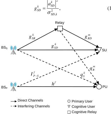
As shown in Figure 1 downlink transmissions are con-sidered, and the corresponding downlink channel gains are defined. Let k
SD
g denote the secondary BS (Source) to SU (Destination) downlink channel gain on subcarrier k, gSRk and
m RD
g denote channel gains of BSS to Relay
on subcarrier k, and relay to SU on subcarrier m respec-tively. Also let hf denote the primary system downlink
channel gain on subcarrier f. The channel gains from BSS
and the relay to PU are defined as k and S
q m
R
q on sub-carriers k and m respectively. As shown in Figure 1,
k SD g , gkSR,
m RD
(solid lines) while qSk and m R
q causes unwanted inter-ference to PU (dashed line). Also let f
P S
I denote inter-fering channel gain from primary BS (BSP) to SU. It’s
assumed that all channel gains are independent from each other, and remain constant in a two-slot period. More-over, all the desired channel gains of the secondary sys-tem and the interfering channel gains from secondary to primary system which are gSDk ,
k SR
g , gRDm , , and k S q m
R
q respectively, are assumed to be perfectly known in BSS. The BSS performs subcarrier pairing and power
allocation, and informs the relay node and the SU of the corresponding parameters through a control signaling prior to data transmission. In next section we will formu-late our optimization problem based on the system model shown in Figure 1.
2.2. Joint Subcarrier Pairing and Power Allocation Problem Formulation
The aim of this paper is to maximize the downlink throughput of secondary system. To formulate our opti-mization problem we have to define our objective func-tion, constraints, and optimization variables. Similar to [14], in our cooperative cognitive model the objective function is the achievable weighted rate of secondary system, which is denoted as k m, for a given subcarrier
pair SP (k, m). Also let , and ,
R S k m
p pk mR denote the trans-mission power of secondary BS in the first time slot and the relay in the second time slot, respectively. Without loss of generality and to make the mathematical formulas simpler in notation, we assume that all the channel gains shown in Figure 1 considered as the normalized channel gains or the Signal-to-Noise-Ratio (SNR) of the corre-sponding channel. As an example we consider gSDk as
2 , , 2 k SD SD a k SD g k (1) Direct Ch Interferin nnels annels g Cha Primary User ser Cognitive U Cognitive Relay BS BS S P SU PU k S q f h f
P S I k SD g m R q k SR
g gRDm
Relay Relay SU PU Primary User tive Us tive Rel Cogni er Cogni ay Direct C
[image:3.595.65.283.493.718.2]Interfering C els hannels hann BS BS S P
Figure 1. Cooperative cognitive radio system model.
where is the channel gain from secondary BS to SU on subcarrier k and is the variance of Additive White Gaussian Noise (AWGN) on the corresponding subcarrier. k SD a 2 , SD k
Since a relay node is used in secondary transmissions, the subcarrier pair SP (k, m), may works in two different modes depending on relay’s activity: direct-link mode and relay mode. In the relay mode the DF relay will for-ward the message in the second time slot on subcarrier m, while in the direct-link mode the message will be sent only via subcarrier k of SD link in the first time slot, and the relay is not used since it will not improve the throughput.
Now that the parameters are defined, we can formulate the achievable weighted rate of secondary downlink for SP (k, m) as [14,15]
, , , , ,log 1 ,
2
direct-link mode
log 1 ,
min ,
2 log 1
relay mode
k S k
SD k m
k S k m
SR k m k
k S k R
SD k m RD k m w
g p
R g p
w
g p g p
(2)
where is a weighting factor to represent Qual-ity-of-Service (QoS) requirements on subcarrier k. Also the rate is scaled by
0
k
w
1 2 since the transmission lasts two time slots.
Introducing total power constraint in secondary system as , , , for SP (k, m), it is shown [16] that
using relay is advantageous and improves the achievable rate if
S R
k m k m k m
p p p
, and .
k k m k
SR SD RD SD
g g g g (3) Similar to [14], by letting following expressions for
and
,
S k m
p R,
k m
p in (2)
,
,
,
,
,
, relay mode
, direct-link mode
, relay mode
0, direct-link mode
k m
k m
m RD
k m
k m k
S
SR RD SD k m
k k
SR SD k m
R k m k
SR RD SD g
p
g g g
P p
g g
p
P g g g
(4)
and defining the equivalent secondary channel gain gk m,
as
,
, relay mode
, direct-link mode
k m SR RD
k m k
SR RD SD k m
k SD
g g
g g g
g g (5)
, log 1
2
k
k m k m k m
w
R g , p , (6) Also we define which indicates whether SP (k, m) is selected or not. Now that we have defined our objective function and the required variables, the WSR optimization problem can be formulated over vari-ables p and t as follows
, 0,1 k m t
,
,
, 1 1P1 max log 1
2
M M k
k m k m k m
k m w
t g
p t p ,
m k k m k m (7) , budget 1 1 s.t. M M k m k m p P
(8), 1 1, M k m k t
(9), 1 1, M k m m t
(10)
, 0,1 , ,
k m
t (11)
, 0, ,
k m
p (12)
, max,
S k k k m S
p q I k (13)
, max,
R m m k m R
p q I m (14) where p and t are MM matrices with entries k m,
and k m, for each SP (k, m), and
p
t Pbudget
max
I
is the total power constraint of secondary system, and max max
is the maximum tolerable interference vector for primary user over each subcarrier. Constraints (8)-(12) are corre-sponded to secondary system limitations, while con-straints (13) and (14) are the primary user interference temperature thresholds.
1 , ,
I IM
3. Weighted Sum Rate Maximization
In this section, we will first solve the WSR maximization problem in the dual domain, and then propose an algo-rithm to achieve feasible solution of the problem based on the optimization results.
3.1. Solution to Optimization Problem [P1]
The defined problem [P1] is a Mixed Integer Program-ming (MIP) problem because of the constraint (11). Due to the fact that the constraint is a set of discrete points, MIP problem is hard to solve. The approach to this kind of problem is to approximate the problem by its con-tinuous relaxation as in [14]. In this technique, instead of constraint (11) which forces to be an integer (either 0 or 1), it will be relaxed to
,
k m t
, 0, ,
k m
t k m (15)
which is a convex constraint set and is more easier to deal with.
Also in [P1], constraints (13) and (14) are power limi-tations on the secondary source and relay respectively, while the optimization variable is k m, as the total
power constraint. To satisfy constraints (13) and (14) and make it in correspondence with k m, , let denote
the maximum total allowed power over subcarrier pair SP (k, m). Using expressions in (4) and combining con-straints (13) and (14), can be immediately derived as
p
p pk mmax,
max , k m p max max max , max ,
min , relay mode
, direct-link mode
k m
k RD
S k m k
SR RD SD m
k m k k
m SR SD
R k m k
SR RD SD k k S I g q
g g g
I p
g g
q
g g g
I q (6)
Using continuous relaxation and maximum total power constraint max in [P1], the relaxed problem becomes
, k m p , , , ,
1 1 ,
1
max log 1
2
M M
k m
k m k k m
k m k m
p
t w g
t
p t (17)
s.t. (8)-(10), and
, 0, ,
k m
t k m
,m
(18)
max
, ,
0 pk m pk m,k (19) The objective function in (17) is the same as [P1] for
, 0,1
k m t
t
. The new relaxed problem is a convex opti-mization problem since its objective function is concave, and the constraints are convex sets [18], and therefore has a unique global solution. But the optimal value of
,
k m may not be an integer. Using the same approach in
[14], we solve the problem in the dual domain and obtain the optimum value of k m, which satisfies (11). This
solution will be an upper bound for problem (17). t
The Lagrangian of problem (12) by using constraints (8) and (9) will be obtained as
,
, ,
1 1 ,
budget , ,
1 1 1 1
, , , 1 log 1 2 1 M M k m k m k k m
k m k m
M M M M
k m m k m
k m m k
L
p
t w g
t P p
p t
t
(20)
where 0 is the Lagrange dual variable, and is the dual Lagrange vector with entries m . The dual
problem will be
, ,
P2 min maxL , , ,
We will first find the optimum value of , by maximizing , k m p
, , ,
L p t over pk m,
to solve the exterior part which is finding the optimum values of and m which satisfy constraints (8) and
(9). The following iterative equations will obtain the op-timum values of and m using the sub-gradient
method , , , , , , , 2 1 k m k m k k m
k m k m
k m k m g
t w t
L p p g t
(22a)
1
,
1 1
M M
i i i i
budget k m k m P
p ,M (26) , , , , 1 0 2 1 k k m k m
k m k m
w L p p g t
(22b) 1
, 1
1 , 1,
M
i i i i
m m k m
k t m
i (27)applying constraint (19), the optimal value of will be , k m p max , * , max max
, , budget
1 1
max
, , budget
1 1
, 0
, if
1
, if 2
k m
k m
M M
k m k m
k m p
M M k
k m k m
k m k m p p p w t g P p P
b where i is the iteration index, and is the step size in the ith iteration. Note that the step size of (26) and (27) can be different. In each iteration the values of k m, and
can be updated using the new values obtained for p
,
k m t
and m in (23) and (25). As the iteration advances,
(26) and (27) will converge and the optimum dual vari-ables will be obtained.
(23)
The original WSR problem [P1] has an integer valued constraint which causes non-convexity of the constraints set. Hence, the curve obtained for WSR optimum value by varying the total power constraint may have discrete changes in its slope. These sudden jumps in the slope of the curve are due to the changes of the optimal SP as the total power varies. This will cause the solution to the relaxed dual problem to be an upper bound for the opti-mum value of [P1]. The gap is known as the duality gap. Recently, it is declared that the duality gap will be zero if the optimum answer of the optimization problem is a concave function of the constraints [20], and therefore the solution of the dual problem is the optimum solution to the original problem. Also it is shown in [21] and used in [14]—same approach as our problem in an OFDM downlink resource allocation problem—that the optimum value of the problem tends to be concave over constraints if the number of subcarriers (M) is large enough. Hence for practical OFDM networks (with ) [14], we obtain the optimum solution to the original problem [P1] by solving the dual problem [P2].
8 M where the following notation is used
,,,
a z a b
z z a z
a
b z b
Equation (23) is known as “constrained water-filling” [19] since it has maximum power constraint . Also called as “multi-level water-filling” because of weighting factor wk.
max ,
k m
p
To obtain the optimum value of , we will rewrite the Lagrangian function (20) as (24)
,
k m
t
In (24), Xk m, and K
,
are independent of t. ,k m
X represents the achievable rate for selected subcar-rier pair SP(k,m) including cost of selecting subcarrier m in second time slot (m) and price of power
consump-tion (the last term in Xk m, ). Hence, the optimum pair for
subcarrier k in first time slot is subcarrier m in second time slot which maximizes Xk m, . It can be readily
de-rived that
3.2. Proposed Algorithm Design
, *
,
1, for arg max
0, otherwise
k m m k m
m X
t
k (25) We apply our solution to [P2] using Algorithm 1. The problem [P2] has two parts, first part is maximizing the
Lagrangian function (21) over variables k m, and tk m, ,
assuming an initial value for dual Lagrange variables, and second part is finding the optimum values for the
p Assuming and m are given we derived k m, and
,
k m in (23) and (25) respectively, and the interior part of
our dual optimization problem is solved. The next step is
* p * t
max max , , , *, , budget
1 1 , 0 , 0 1
,
1 1
, , , log 1
2 2 2
k m k m
k m
p p
M M M
k k k
k m k m m m
k m k m k m m
K X
w w w
L t g P
g g
α p t Lagrange dual variables and m to minimize (21)
with the values of k m, and tk m, obtained in the first
part. In section 3.1 a closed form solution for the first part is derived in Equations (23) and (25). While for the second part a sub-gradient method is discussed to find the optimum values of
p
and m using iterative
Equa-tions (26) and (27). In Algorithm 1, we will first initialize the required variables. In each iteration, we will first calculate the optimum value of k m, and k m, using
Equations (23) and (25), and then find new values for
p t
and m with the corresponding equations. The loop
will continue until the dual Lagrange parameters verge to their optimum values which minimize the con-straints cost. Since constraint (9) is guaranteed by equa-tion (25), while constraint (10) may be violated, an amendment is used to avoid selecting the same relay subcarrier for more than one source subcarriers, which results in more than one “1”s in a column of t and violate constraint (10) [14]. This amendment is applied at the last 10% of the algorithm iterations. At the last step a constrained water-filling is applied to find the optimum power allocation using to maximize WSR for sec-ondary system while the interference threshold of the primary network is not violated. The optimum subcarrier pairing scheme and power allocation which maximize WSR of secondary system while preserving QoS of pri-mary network in an OFDM based cooperative cognitive network is obtained by using this algorithm.
* ,
k m
t
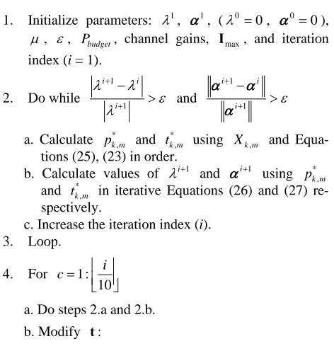
Algorithm 1. Joint Subcarrier Pairing and Power Alloca-tion for SU WSR MaximizaAlloca-tion in Cooperative Cognitive Network
1. Initialize parameters: 1, 1, (0 0, 00),
, , Pbudget, channel gains, Imax, and iteration
index (i = 1).
2. Do while
1
1
i i
i
and
1
1
i i
i
a. Calculate * and using
,
k m
p *
,
k m
t Xk m, and Equa-tions (25), (23) in order.
b. Calculate values of i1
and i1
using and in iterative Equations (26) and (27) re-spectively.
* ,
k m
p
* ,
k m
t
c. Increase the iteration index (i). 3. Loop.
4. For 1: 10
i
c
a. Do steps 2.a and 2.b.
b. Modify t:
i. While , , for any m.
1
1
M k m k
t
ii. In each column of t which contains more than one “1”s (source column) keep the “1” which results in the largest Xk m, .
iii. Find the column with no “1”s (destination col-umn) which has the minimum change to m with the source column.
iv. Change a “1” in the source column (other than the “1” which is kept in 4.b.ii) with a zero in the destination column, in a row which causes the largest Xk m, in the destination column. v. Loop.
a. Do Constrained Multi-level Water-Filling with
k
w , Pbudget , and max
,
k m
p obtained from * ,
k m t , and Imax.
b. Calculate corresponding WSR using (6). 5. End.
4. Numerical Results and Simulations
In this section the proposed method for our Cooperative Cognitive Radio Network, as shown in Figure 1, is benchmarked through extensive simulations. As we men-tioned all the channel gains k
SD g , k
SR g , m
RD g , k,
S
q m
R q ,
f
h , and f P S
I are independent of each other, and remain constant in a two-slot period. Also it is assumed that the channel gains are independent and identically distributed (i.i.d.) over subcarriers and follow a Rayleigh distribu-tion with parameter b differs from one link to another corresponding to the mean square of subcarrier channel gains in different scenarios. The variance of Additive White Gaussian Noise (AWGN) is assumed to be one.
In Algorithm 1, the initial value of dual Lagrange mul-tipliers are set as 1 1, and . The convergence criterion is
1 1 0.01
, and the step size for the subgradi-ent method is set to be i 0.05 i
w
, where i is the it-eration index. In Un-Weighted Sum Rate (UWSR) sce-nario, the weighting factor k is set to be all “1” for
different subcarriers, and in Weighted Sum Rate (WSR) scenario, it obeys the equation wk 1
k1
M1
. The results are obtained based on 1000 randomly gener-ated channel realizations.Two different system configurations corresponding to the position of the relay node are investigated. In the first scenario it is assumed that the relay node is placed be-tween the secondary source and destination. The mean square of channel gains in this scenario, are set as
2 3
SR
[image:6.595.55.291.486.734.2]straint for secondary system is assumed to be Pbudget 5
[Watts], and the maximum tolerable interference for primary user is equal to Imax 1M over all subcarriers.
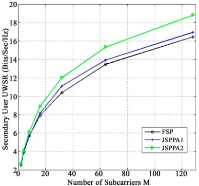
In this figure the WSR of the Fixed Subcarrier Pairing (FSP) method—where for every subcarrier pair —is compared to the Joint Subcarrier Pairing and Power Allocation (JSPPA) approach. In JSPPA1 we only apply the maximum power constraint for Constrained Water-Filling in the last part of Algorithm 1, while in JSPPA2 the is considered in both subcar-rier pairing and power allocation to find optimum values
and respectively. As it is shown in Figure 2, a 17% improvement in WSR is acquired with JSPPA2 when we have subcarriers. Figure 3 shows the UWSR for secondary system, exploiting FSP, JSPPA1, and JSPPA2 methods with same assumptions.
km
max ,
k m p
, SP k m* ,
k m t
max ,
k m p
* ,
k m p
[image:7.595.318.527.269.468.2]64 M
Figure 2. WSR of secondary system, when the relay is be-tween the secondary source and destination.
Figure 3. UWSR of secondary system, when the relay is between the secondary source and destination.
In the second scenario, the relay node is placed close to the secondary source. The mean square of channel gains in this scenario, are set as
2 5
SR
E g , E g SD2 1, and E g RD2 1. All other assumptions are the same as the previous sce-nario. Figures 4 and 5 show the secondary system’s WSR and UWSR respectively through different number of subcarriers. In this scenario the improvement in WSR for M 64 subcarriers is 9%.
When the relay node is between the secondary source and destination, in Figure 6 we have shown the WSR of secondary system by varying the total available power
budget
[image:7.595.71.273.284.478.2]P for M 64 subcarriers. And Figure 7 shows
Figure 4. WSR of secondary system, when the relay is close to the secondary source.
[image:7.595.317.530.507.705.2] [image:7.595.70.275.514.705.2]Figure 6. WSR of secondary system through different val-ues of Pbudget, for M64 subcarriers.
Figure 7. WSR of secondary system through different val-ues of Imax, for M64 subcarriers and Pbudget 5 W.
the WSR of secondary system by varying the tolerable interference for subcarriers and fixed total power budget [Watts]. Both Figures 6 and 7 show
that the JSPPA method outperforms the FSP.
64
M
5
P
5. Conclusion
In this study we consider an OFDM based cooperative cognitive network with a pair of Source-Destination nodes as the primary user (PU), and a pair of Source- Destination nodes—which is assisted with a relay—as the secondary user SU. In a shared spectrum underlay paradigm, downlink transmission of the secondary sys- tem using a half-duplex relay with DF method under total power constraint is considered. Under defined constraints
set, a joint subcarrier pairing and power allocation is proposed for SU to maximize its WSR. The problem is transformed to a convex optimization problem using continuous relaxation method, and solved in the dual domain. In large enough number of subcarriers (M) the solution to dual problem will tend to the optimal WSR solution. An algorithm to achieve feasible solutions is used based on the dual optimization results. The algo-rithm has two parts, the first part is to find the optimum values for optimization variables which are power allo-cation and subcarrier pair scheme, and second part is to minimize the Lagrangian function over Lagrange dual variables. Through extensive simulations, the spectrum utilization of the proposed approach is benchmarked, and compared with the existing ones. Interestingly it is shown that the proposed method improves the weighted sum rate of SU, and the simulations endorse our mathematical proofs. Simulations show that in best conditions the pro-posed method JSPPA2 improves the WSR of SU by 17% in respect to the fixed subcarrier pairing (FSP) method. Cooperation in multiuser primary and secondary systems with more relay nodes can be considered in future re-searches by using the same optimization approach. Also using the proposed method for cooperative cognitive networks which obey overlay paradigm, where cognitive relay nodes can help even primary users to enhance their data transmission, can be a subject of interest in future studies.
6. Acknowledgements
The authors wish to acknowledge the partial support of Iran Telecommunication Research Center (ITRC).
REFERENCES
[1] Federal Communications Commission Spectrum Policy Task Force, “Report of the Spectrum Efficiency Working Group,” 2002.
http://www.fcc.gov/sptf/files/SEWGFinalReport_1.pdf
[2] J. Mitola, “Cognitive Radio: An Integrated Agent Archi-tecture for Software Defined Radio,” Ph.D. Thesis, KTH Royal Institute of Technology, Stockholm, 2000.
[3] S. Haykin, “Cognitive Radio: Brain-Empowered Wireless Communications,” IEEE Journal on Selected Areas in Communications, Vol. 23, No. 2, 2005, pp. 201-220. doi:10.1109/JSAC.2004.839380
[4] C. R. Stevenson, G. Chouinard, Z. Lei, W. Hu and S. J. Shellhammer, “IEEE 802.22: The First Cognitive Radio Wireless Regional Area Network Standard,” IEEE Com-munications Magazine, Vol. 47, No. 1, 2009, pp. 130- 138. doi:10.1109/MCOM.2009.4752688
[image:8.595.66.277.318.516.2]Information Theoretic Perspective,” Proceedings of the IEEE, Vol. 97, No. 5, 2009, pp. 894-914.
doi:10.1109/JPROC.2009.2015717
[6] T. Luo, F. Lin, T. Jiang, M. Guizani and W. Chen, “Mul-ticarrier Modulation and Cooperative Communication in Multihop Cognitive Radio Networks,” IEEE Wireless Communications, Vol. 18, No. 1, 2011, pp. 38-45. doi:10.1109/MWC.2011.5714024
[7] Q. Zhang, J. Jia and J. Zhang, “Cooperative Relay to Improve Diversity in Cognitive Radio Networks,” IEEE Communications Magazine, Vol. 47, No. 2, 2009, pp. 111-117. doi:10.1109/MCOM.2009.4785388
[8] N. Golrezaei, P. Mansourifard and M. Nasiri-Kenari, “Multi-Carrier Based Cooperative Cognitive Network,”
IEEE 73rd Vehicular Technology Conference, Budapest, 15-18 May 2011, pp. 1-5.
[9] J. Lou, T. Luo and G. Yue, “Power Allocation for Coop-erative Cognitive Networks,” IEEE 3rd International Conference on Broadband Network and Multimedia Technology, Beijing, 26-28 October 2010, pp. 412-416. [10] C. H. Chen, C. L. Wang and C. T. Chen, “A Resource
Allocation Scheme for Cooperative Multiuser OFDM- Based Cognitive Radio Systems,” IEEE Transactions on Communications, Vol. 59, No. 11, 2011, pp. 3204-3215. doi:10.1109/TCOMM.2011.092011.100197
[11] L. Li, X. Zhou, H. Xu, G. Y. Li, D. Wang and A. Soong, “Simplified Relay Selection and Power Allocation in Cooperative Cognitive Radio Systems,” IEEE Transac-tions on Wireless CommunicaTransac-tions, Vol. 10, No. 1, 2011, pp. 33-36. doi:10.1109/TWC.2010.101810.100311
[12] W. C. Ao, S. M. Cheng and K. C. Chen, “Power and In-terference Control with Relaying in Cooperative Cogni-tive Radio Networks,” IEEE International Conference on Communications, Cape Town, 23-27 May 2010, pp. 1-5. [13] C. Zhao and K. Kwak, “Joint Sensing Time and Power
Allocation in Cooperatively Cognitive Networks,” IEEE
Communications Letters, Vol. 14, No. 2, 2010, pp. 163- 165. doi:10.1109/LCOMM.2010.02.092102
[14] C. N. Hsu, H. J. Su and P. H. Lin, “Joint Subcarrier Pair-ing and Power Allocation for OFDM Transmission With Decode-and-Forward Relaying,” IEEE Transactions on Signal Processing, Vol. 59, No. 1, 2011, pp. 399-414. doi:10.1109/TSP.2010.2081982
[15] T. M. Cover and A. A. E. Gamal, “Capacity Theorems for the Relay Channel,” IEEE Transactions on Information Theory, Vol. 25, No. 5, 1979, pp. 572-584.
doi:10.1109/TIT.1979.1056084
[16] L. Vandendorpe, R. T. Duran, J. Louveaux and A. Zaidi, “Power Allocation for OFDM Transmission with DF Re-laying,” IEEE International Conference on Communica-tions, Beijing, 19-23 May 2008, pp. 3795-3800.
[17] W. Ying, Q. Xin-chun, W. Tong and L. Bao-ling, “Power Allocation and Subcarrier Pairing Algorithm for Regen-erative OFDM Relay System,” IEEE 65th Vehicular Technology Conference, Dublin, 22-25 April 2007, pp. 2727-2731.
[18] S. Boyd and L. Vandenberghe, “Convex Optimization,” Cambridge University Press, Cambridge, 2004.
[19] N. Papandreou and T. Antonakopoulos, “Bit and Power Allocation in Constrained Multicarrier Systems: The Sin-gle-User Case,” EURASIP Journal on Advances in Signal Processing, Vol. 2008, 2008, Article ID: 643081. doi:10.1155/2008/643081
[20] W. Yu and R. Lui, “Dual Methods for Nonconvex Spec-trum Optimization of Multi-Carrier Systems,” IEEE Transactions on Communications, Vol. 54, No. 7, 2006, pp. 1310-1322. doi:10.1109/TCOMM.2006.877962
[21] K. Seong, M. Mohseni and J. M. Cioffi, “Optimal Re-source Allocation for OFDMA Downlink Systems,” IEEE International Symposium on Information Theory, Seattle, 9-14 July 2006, pp. 1394-1398.