43
The Capacity of Mesh Cell based on Fixed WiMAX
System
Firas Sami Alsharbaty
Department of Electrical Engineering
College of Engineering
University of Mosul/IRAQ
Mohammed Younis
Department of Electrical Engineering
College of Engineering
University of Mosul/IRAQ
ABSTRACT
A Worldwide interoperability for Microwave Access (WiMAX) cell which is to be considered in this research applies mesh mode of operation with centralized scheduling. The direct connection between subscribers in many cases without the need of base station gives an improvement of the signal to noise ratio especially among users with short distances but the advantage of the mesh mode is tumbled when the number of users is increased significantly. This is related to the great increment in the overhead, the high processing during hops and the need for complex routing algorithm. Other factors like MAC and PHY layers overheads are studied and taken into account in the calculation of the cell capacity.
General Terms
Analysis, Frame Format, Mathematical Model, Scheduling.
Keywords
Capacity, Mesh mode, Overhead, WiMAX.
1.
INTRODUCTION
Mesh mode is a peer-to-peer mode of communication; a subscriber can communicate via multihop routing or forwarding to another one. A wireless network that supports mesh mode communication is called a wireless mesh network [1]. Mesh mode gives a subscriber an opportunity to transfer data through relaying nodes. Each subscriber station (SS) of a network has the capability to behave like a relay. An SS listens to network configuration messages (called MSH-NCFG) which are periodically transmitted by all subscribers in a network. From these messages, there can be obtained: i) coarse synchronization with a network, ii) basic network parameters, and iii) a list of neighbours. Subsequently, an SS selects a potential subscriber from adjacent subscriber and starts to negotiate and establish a temporary connection called sponsor channel. The created channel is used by SS to registrate to the network and to establish internet protocol (IP) connection using dynamic host configuration protocol (DHCP).
The potential SS is allowed to accept or refuse the request for sponsor channel opening. An acceptance is signalized with MAC address advertisement in MSH-NCFG message during the whole negotiation process. After the successful SS network entry, the user can set up other connections to the neighbouring subscribers. The 802.16-2004 standard doesn’t specify rules how a SS selects potential subscriber or any other adjacent subscribers to connect to.
It is worth to mention that Mesh mode supports time division duplex (TDD) only, it defines three scheduling mechanisms schemes: centralized, coordinated distributed and uncoordinated distributed scheduling [2][3]. A base station (BS) in centralized scheduling gathers resource requests from all the mesh SSs within a certain hop range. It then determines the amount of resources to grant to each link in the network in both downlink and uplink, and relays these grants through SSs within one-hop range [4]. Distributed scheduling is done by exchanging requests and grants in the extended neighborhood of the communicating SSs, which consists of the direct neighbors (one-hop) and their neighbors (two-hop neighbors) [5].This research deals with the centralized scheduling only leaving other types.
2.
THEORY
2.1 PHY Layer
The physical (PHY) layer of WiMAX is based on IEEE 802.16-2004 standard for fixed SSs. The primary function of PHY layer is the physical transport of data through channels.
According to [6], the channel bandwidth may vary from 1.75 MHz to 28 MHz The bigger channel size can provide more radio resources and thus capacity of the system is larger . To prevent inter symbol interference (ISI) caused by delay spread, part of the OFDM symbol is appended at the beginning of the symbol. The repeated symbol fraction is called cyclic prefix (CP) and its size depends on type of environment. From bandwidth size and CP values, symbol time duration )time of one symbol) can be derived .
In case of OFDM modulation used in 802.16 standards, the bandwidth is divided into 256 subcarriers. When pilot and null subcarriers are subtracted, the remaining 192 subcarriers can be used to carry user’s data. The capacity of each subcarrier depends on the order of used modulation. WiMAX standard supports BPSK (1 bit per subcarrier), QPSK (2 bits per subcarrier), 16QAM (4 bits per subcarrier) and finally 64 QAM (6 bits per subcarrier) [7].
Because of errors introduced by imperfection of the channel, Reed Solomon is used, it provides redundant bits which must be carried with useful information for the purpose of error detection and correction at the receiver. The ratio of information to information plus redundant bits is called coding rate and may vary from ½ to 4/5 .
44 Table 1. The parameters of PHY
2.2
MAC Layer of Centralized Scheduling
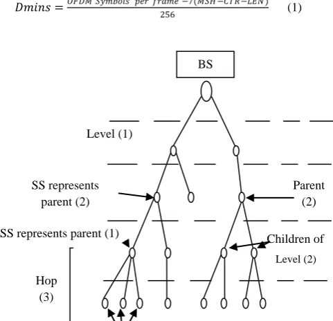
Centralized scheduling is performed using two main types of messages: the Mesh Centralized Scheduling (MSH-CSCH) message and the Mesh Centralized Scheduling Configuration (MSH-CSCF) message. Each SS gathers its children's (subscribers which rely on it) requests and reports them along with its own in a MSH-CSCH request to its parent (see Figure 1). The whole process repeats recursively until the requests are propagated towards the BS. The BS then determines the flow assignments and broadcasts a MSH-CSCH Grant, which is rebroadcasted by intermediate SS’s until all subscriber stations in the network receive it. SSs determine their scheduling in a recursive manner by using a common algorithm that divides the frame proportionally. According to this Request/Grant procedure, WiMAX mesh networks cannot support more than 100 subscribers. Moreover, as the tree depth increases the control information reduces the available slot space for data, thus decreasing the achievable throughput [5].
2.2.1 Frame Structure
MAC protocol of IEEE 802.16 mesh mode is based on time division multiple accesses (TDMA); it is built on a time division multiplexing (TDM) physical layer. The time in this layer is divided into slots of equal duration, and during each slot a packet is transmitted. This mode uses Orthogonal Frequency Division Multiplexing (OFDM) to implement the TDM physical layer.
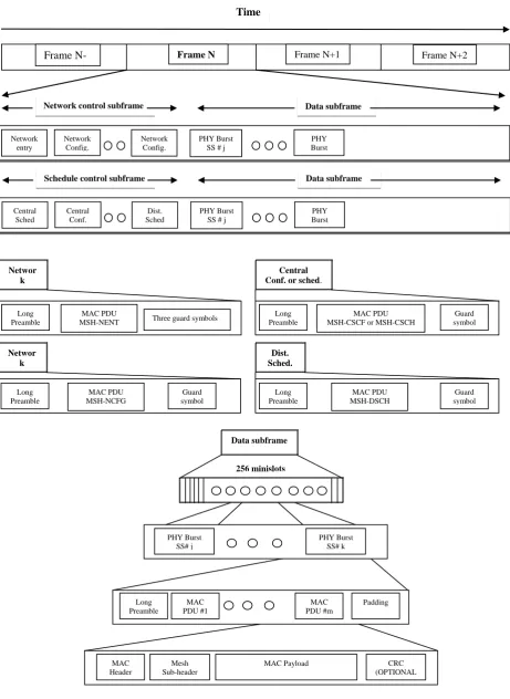
According to OFDM, blocks of bits are transformed into constant duration symbols carried on multiple, orthogonal, carriers. The symbols are grouped into TDMA frames of equal length, the frames must be repeated over time to provide smooth transmission of data to users. Figure 2 shows the structure of a mesh frame which constitutes of: control and data subframes. It is worth mentioning that, scheduling will compute the range and position of minislots in a frame. A minislot is a unit of bandwidth allocation equivalent to a certain number of physical slots. The duration of a minislot is fixed , and each minislot contains a specific number of orthogonal frequency-division multiplexing (OFDM) symbols. The data rate attainable in a minislot depends on the coding and modulation schemes utilized at transmission time. The symbols in the control subframes are grouped into transmission opportunities with a fixed length of seven OFDM symbols. Four of the symbols are used to transmit information at the lowest bit rate, while the other three are used as guard symbols [8]. There are two types of control
subframes: schedule control and network control. The latter is signaled periodically and further comprises two messages: MSH-NENT and MSH-NCFG. The schedule control subframe is partitioned into two subframes. The first one is used for exchanging centralized scheduling messages, MSH-CSCH and MSH-CSCF while the second subframe is used for exchanging coordinated distributed scheduling messages (MSH-DSCH). All transmissions apply (QPSK) 1/2 modulation over the broadcast channel and start with long preamble and finish with guard symbol (except MSH-NENT which is finished with three guard symbols). Data is transmitted in the data subframe. The size of a data minislot depends the length of control subframe. According to 802.16-2004 standard, the length of the control subframe is fixed and of length CTRL-LEN*7 OFDM symbols. Where MSH-CTRL-LEN is a network parameter transmitted in the network configuration subframe [9]. Therefore, the size of a data minislot (Dmins) is computed by:
𝐷𝑚𝑖𝑛𝑠 =𝑂𝐹𝐷𝑀 𝑆𝑦𝑚𝑏𝑜𝑙𝑠 𝑝𝑒𝑟 𝑓𝑟𝑎𝑚𝑒 −7(𝑀𝑆𝐻 −𝐶𝑇𝑅−𝐿𝐸𝑁)
256 (1)
Fig 1: Mesh Tree
The reason for limiting the number of transmission opportunities in the data-subframe to 256 is related to fields referring to transmission opportunities in 802.16 scheduling packets which are 8-bits long [9].
The data subframe consists of groups of PHY bursts, every burst start with long preamble and contains many MAC PDU’s. Each PDU is started with MAC header (6 bytes) followed with mesh subheader (2 bytes). After mesh subheader, MAC payload had variable length (0-2039) bytes. MAC PDU is finished with optional CRC (4 bytes).
Transmission opportunities are assigned to logical channels. There are three types of logical channels: basic, broadcast and data [9]. The basic channel is used for ranging and network entry packets, the broadcast channel is used to transmit mesh control packets, and the data channels are used for data packets and some 802.16 control packets.
PARAMETERS VALUE
BANDWIDTH BW ( MHz) 20
symbol useful time ( µs) 11.64
CP time (µs) 2.91
overall symbol time ( µs) 14.55
OFDM Subcarriers 256
Data Subcarriers 192
At coding rate1/2, PHY OVERHEAD (%) 71.88 At coding rate3/4, PHY OVERHEAD (%) 57.81
DUPLEX TYPE TDD
Access FIXED
Number of BS 1
Number of SSs 50
Frame duration (ms) 20
frequency band (GHz) 5
Level (2)
Level (3)
SS,s represent children of parent (1)
Parent (2)
Children of parent (2) SS represents
parent (2)
SS represents parent (1)
Hop (3)
Level (1)
[image:2.595.305.546.279.511.2]45 Level (2)
Parent (2)
Children of parent (2) SS represents parent
(2)
SS represents parent (1) Level (1)
BS Networ
k Entry
Long Preamble
MAC PDU
MSH-NENT Three guard symbols
Central Conf. or sched.
Long Preamble
MAC PDU MSH-CSCF or MSH-CSCH
Guard symbol
Networ k Conf.
Long Preamble
Guard symbol MAC PDU
MSH-NCFG
Dist. Sched.
Long Preamble
MAC PDU MSH-DSCH
Guard symbol
Long Preamble
MAC PDU #1
MAC PDU #m
Padding
MAC Header
Mesh Sub-header
MAC Payload CRC (OPTIONAL
)
Data subframe
PHY Burst SS# j
PHY Burst SS# k
256 minislots
Frame
N-1
Frame N Frame N+1 Frame N+2
Time
Network entry
Network Config.
Network Config.
PHY Burst SS # j
PHY Burst SS # k
Network control subframe Data subframe
Schedule control subframe Data subframe
Central Sched
Central Conf.
Dist. Sched
PHY Burst SS # j
[image:3.595.81.543.83.716.2]PHY Burst SS # k
46 The basic channel is allocated in the control sub-frame. Some
[image:4.595.306.562.123.251.2]slots used by the broadcast channels are in the control sub-frame and some are in the data sub-sub-frame. All data channel slots are located in the data sub-frame. The basic channel and the data channels are unicast since only one node is supposed to process transmissions from the channel, while the messages in the broadcast channel are intended for all first-hop neighbours of a subscriber. The channels are closely related to the types of packets transmitted in them; Table 2 summarizes the relationship between the mesh control packet types and channel types .The basic channel is used by subscribers entering the network to transmit the network entry NENT packets. Broadcast channels are used to transmit MSH-NCFG, network configuration messages, and MSH-CSCF, MSH-CSCH and MSH-DSCH scheduling messages. There are three types of broadcast channels, depending on how transmission opportunities in the channel are shared. There are two reliable broadcast channels that use coordinated transmissions to prevent collisions. The first uses distributed election based scheduling for MSH-NCFG and MSH-DSCH messages. The second uses tree based scheduling for MSH-CSCH and MSH-CSCF messages. Optionally, MSH-DSCH messages can also be transmitted in the unused data slots of the data sub-frame, in an additional unreliable broadcast channel [9].
Table 2. Mesh control messages of WiMAX
3. ANALYSIS AND DESIGN OF MESH
3.1 MAC Overhead Calculations
Figure 3 explains the frame format of mesh mode. It consists of Control and Data sub-frames. Control subframe can be either, network or schedule control subframes. The messages of network control subframe usually occur at the beginning of any connection and may be repeated occasionally to keep the network performance perfectly. Therefore the overhead contribution of this subframe can be neglected.
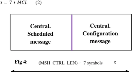
On the other hand, schedule control is divided into: centralized and distributed schedules. This research deals with centralized schedule. Figure 4 shows that this schedule
consists of two types of messages: centralized schedule CSCH) and centralized configuration messages (MSH-CSCF).
Fig 3: MAC frame of Mesh mode of operation
The overhead of centralized schedule control subframe (in MAC layer introduced by MSH-CSCF and MSH-CSCH messages) can be evaluated as a number of OFDM symbols [10]:
[image:4.595.317.542.331.455.2]𝜇 = 7 ∗ 𝑀𝐶𝐿 (2)
Fig 4: Centralized schedule control subframe
Where, MCL (MSH_CTRL_LEN) is a network parameter and can be estimated by the following formula:
𝑀𝐶𝐿 =𝑂𝐻𝛽 +𝑂𝐻𝛿
𝐵𝑝𝑠 1 (3)
Equation (2) can be rewritten as:
µ = 7(𝑂𝐻𝛽 +𝑂𝐻𝛿
𝐵𝑝𝑠 1 ) (4)
Where:
𝑂𝐻ß = the overhead that introduced by MSH-CSCF message
𝑂𝐻𝛿 = the overhead that introduced by MSH-CSCH message
𝐵𝑝𝑠1 = the number of bytes per symbol at QPSK modulation and ½ coding rate
𝑂𝐻ß can be estimated from following formula in bytes [9]:
𝑂𝐻𝛽 = 3 + 0.5 ∗ 𝑁𝑐 + 2 ∗ 𝑚𝑓 + 3 ∗ 𝑁 (5)
𝑂𝐻𝛿 can be estimated from following formula in bytes:
𝑂𝐻𝛿 = 4 + 𝑚𝑓 (6)
Where:
Nc = the number of available channels in the band assigned to the Mesh BS
mf = the maximum number of links that can be established Message type Channel
type Scheduling Purpose
MSH-NENT Basic Best effort Network entry
MSH-NCFG Broadcast Distributed election
Network
configuration
MSH-CSCF Broadcast Tree scheduling
Centralized scheduling
configuration
MSH-CSCH Broadcast Tree scheduling
Centralized schedule distribution
MSH-DSCH Broadcast
Distributed election, Best effort
Decentralized scheduling negotiation
Control
subframe
Data
subframe
One frameµ (Symbols)
Network control or schedule control
subframes
(MSH_CTRL_LEN) ⋅ 7 symbols
Central.
Scheduled
message
Central.
Configuration
[image:4.595.51.289.387.609.2]47 N = the number of SSs in the wireless network, under control
of the Mesh BS
3.2 Capacity Calculation
The effective length in one MAC frame is calculated after the subtraction of the length of overheads of PHY and MAC layers from the overall length of the frame:
𝑆 = 𝑂𝐻𝑅 ∗ 𝐾 (7)
Where:
OHR = the ratio of the effective length to the length of a frame
K = the overall length of frame
S = the effective length of frame after the subtraction of the overhead ratio
The number of symbols in one MAC frame can be calculated by the following formula:
𝑇 =𝑆
𝐶 (8)
Where: C is length of one symbol.
The symbols that are used for useful data can be estimated by the following formula:
𝐷 = 𝑇 − 𝜇 (9)
Where:
D = the symbols that used for useful data.
T = the number of OFDM symbols in one MAC frame after the subtraction of the overhead from the overall length of the frame
µ = the symbols that used for schedule control subframe (the overhead)
The system capacity to requested capacity of mesh mode can be calculated by the following formula [7]:
𝑆𝑐 𝑅𝑐=
𝐷
𝑅𝐸𝑄 (𝐷) (10)
Where REQ (D) represents the number of OFDM symbols that are needed to transfer a given nominal bit rates for all active users in the range of BS and can be calculated as follow:
The requested capacity can be estimated from the following formula [10][11] :
𝑅𝐸𝑄 𝐷 = 𝐵𝑅 ∗ 𝐿𝑜𝐹 ∗ 𝑆𝑆(𝐵𝑆)
𝑏𝑝𝑠𝑖 7
𝑖=1 (11) Where:
BR = the nominal bit rate in bits per second LoF = Length of frame in second
SS (BS) represents the number of SSs that use individual modulation type and coding rate
Bpsi = Number of bits allocated to one OFDM symbol
It is worth mentioning that the overhead introduced by other MAC messages and mesh subheader as well as by MAC PDU (packet data unit) headers is neglected (due to their small values).
4.
SIMULATION MODEL
The simulation of WiMAX system performance in mesh mode is based on the following assumptions:
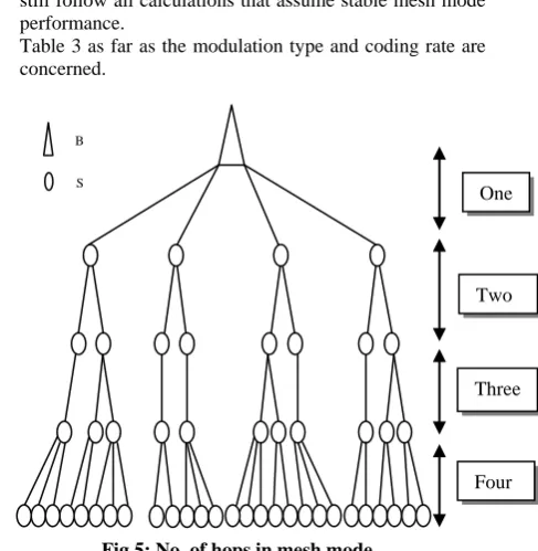
- WiMAX cell consists of one BS and up to 50 SSs, see Figure 5.
- All SSs under coverage of BS (centralized scheduling). - The maximum number of hops in the tree is equal to four. - The modulation type and coding rate depend on the
strength of the signal to noise ratio in the link between two SSs, see Table 3.
- A connection is possible between any two neighbors in the tree directly or between SSs through single or multiple hops.
- The tree is allowed to change six times but keeping the same number of users and hops, this means that they are still follow all calculations that assume stable mesh mode performance.
- Table 3 as far as the modulation type and coding rate are
concerned.
[image:5.595.321.565.254.504.2]Fig 5: No. of hops in mesh mode
Table 3. The modulation types and coding rate of the links in the tree of the assumed six states
5. THE RESULTS
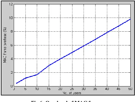
Figure 6 shows the overhead that must be introduced in the MAC layer of the mesh mode of operation.
Modulation and coding
rate
First state (No. of
users)
Second state
Third state
Fourth state
Fifth state
Sixth state
QPSK 1/2 3 0 5 0 2 3 QPSK 3/4 7 1 6 0 10 2 16 QAM 1/2 12 12 14 5 12 13 16 QAM 3/4 12 18 19 20 17 12 64 QAM 2/3 12 15 2 20 5 14 64 QAM 3/4 4 4 4 5 4 6
B S S
S One
hop
Two hops
Three hops
[image:5.595.315.572.555.729.2]48 With the increment in the number of the users, the overhead
[image:6.595.316.552.79.238.2]of MAC frame is increased due to the additional increment in the messages control part.
Fig 6: Overhead of MAC frame
The system capacity to requested capacity with the increment in the value of the number of the users of mesh mode at BR = 1Mbps is illustrated in Figure 7.
Fig 7: Sc/Rc versus No. of users in mesh mode at BR = 1Mbps
It is obvious that the system performance in mesh mode can provide 25 users with the services required, while the system fails to provide users with required services for all values greater than 25 (i.e. congestion occurs).
Figure 8 shows the system capacity to requested capacity with the nominal bit rates for different numbers of users.
When the bit rate is increased, the system capacity to requested capacity is decreased. This is related to the increment in the requested capacity.
Fig 8: Sc/Rc versus nominal bit rates
6. CONCLUSION
This paper dealt with the analysis and calculation of the overheads of PHY and MAC layers. The analysis of mesh mode shows that the system capacity to requested capacity is a function of the SNR ratio and the number of users. The magnitude of the SNR ratio is further improved as compared with classical mode of WiMAX (point to multipoint); this is related to the principles of mesh operation where there are many cases the communication is conducted between users without the need to the base station ( i.e. through the relay station). The results of centralized scheduling show that, the system capacity to requested capacity is decreased with the increment of the number of users and nominal bit rates. This is related to the portion of the frame which is occupied by the overheads is significant and gradually increased as well as the increment of requested capacity, at nominal bit rate equal to less than 3Mbps, 10 users can utilize the system resources of the cell successfully before congestion occurs. The future scope of this paper will deal with optimizing the capacity of the mesh cell in centralized scheduling by using routing algorithms and employing the mesh mode in decentralized scheduling.
7. REFERENCES
[1] Tung D., Wong C., Kong Y., Liang Ch., Chua C. and Mark J. 2009. Wireless Broadband Networks. John Wiley & Sons, Inc.
[2] Zhu H., Tang Y. K., and Chlamtac I., Unified Collision-Free Coordinated Distributed Scheduling (CF-CDS) in IEEE 802.16 Mesh Networks. Vol. 7, No. 10, PP 3889-3903.
[3] Ahson S. and Ilyas M., 2008. WiMAX Technologies, Performance Analysis, and QoS. Taylor & Francis Group, LLC.
[4] Abu Ali N. A., Taha A.E. M., Hassanein H. S. and Mouftah H.T., 2008. "IEEE 802.16 Mesh Schedulers: Issues and Design Challenges". IEEE Network magazine, Vol. 22, Issue 1, PP 58-65.
[5] Nahle S., Iannone L., Donnet B., and Friedman T. 2007. Trade-Off in WiMAX Mesh Networks. University of Pierre et Marie Curie - Laboratoire LIP6/CNRS and UniversityCatholique de Louvain CSE Department.
[6] IEEE Standard 802.16-2004 2004. Part 16: Air Interface for Fixed Broadband Wireless Access System. IEEE Standard for Local and metropolitan area networks, Revision of IEEE Std 802.16.
[image:6.595.53.284.124.298.2] [image:6.595.55.283.351.533.2]49 [7] Mach P. and Bestak R. WiMAX performance evaluation.
IEEE Networking, Sixth International Conference, vol. 22, issue 28, PP 12-17.
[8] Ahson S. and Ilyas M., 2008 " WiMAX Standards and Security ", Taylor & FrancisGroup, LLC
[9] Redana S. and Lott M., 2004 "Performance Analysis of IEEE 802.16a in Mesh Operation Mode". Information and Communication Mobile, Munich, PP 1-6,.
[10]Mach P. and Bestak R, 2008 “WiMAX Throughput Evaluation of Conventional Relaying”, DOI, Springer Science and Business Media, PP 11–17.
[11]Rangineni S. K., 2008, Multihop Concept in Cellular Systems, Master Thesis, University of Gävle, Sweden.