doi:10.4236/epe.2011.31009 Published Online February 2011 (http://www.SciRP.org/journal/epe)
A Digital Phase Locked Loop Speed Control of Three
Phase Induction Motor Drive: Performances Analysis
Ben Hamed Mouna, Sbita Lassaâd
Department of Electrical Engineering, National Engineering School of Gabes, Tunisia E-mail: benhamed2209@yahoo.fr, [email protected]
Received October 22, 2010; revised November 3, 2010; accepted November 13, 2010
Abstract
This paper deals with performance analysis and implementation of a three phase inverter fed induction motor (IM) drive system. The closed loop control scheme of the drive utilizes the Digital Phase Locked Loop (DPLL). The DPLL is safely implemented all around the well known integrated circuit DPLL 4046. An ex-perimental verification is carried out on one kw scalar controlled IM system drives for a wide range of speeds and loads appliance. This presents a simple and high performance solution for industrial applications.
Keywords:Digital Phase Locked Loop (DPLL), Induction Motor, Scalar Strategy, Speed Drives and Load Appliance
1. Introduction
IMs are used in many industry sectors as the leading element to convert electrical energy into mechanical one. The main challenge is based on robustness and low cost. The performance of the motor speed control required in the industrial drives depends on the application specifi-cations. In some applications, an open loop speed varia-tion of the drive motor is enough. In others, feedback control is required for better speed regulation perform-ances. The performances of the speed regulation depend on the performances of the speed controller. In light of available literature, important aspects of the motor drive system, it is considered worthwhile to review it critically in order to find the gaps existing knowledge on the IM drive systems. Researchers have used various types of closed loop controllers for the IM rotor speed. PI con-trollers are widely and still used in the outer speed loop [1,2]. They have a simple structure and can offer a satis-factory performance for a wide range of operation. Due to the continuous variation in the plant parameters and the non linearities conditions, PI controllers may become unable to provide the required control performance [3,4]. These inherent disadvantages of the PI controllers have encouraged the replacement of this controller with adap-tive [5,6] and robust [7-9] control laws. Adapadap-tive control laws impose a very computation burden while H∞ robust control requires the knowledge of the disturbances boundaries [7]. Sliding mode control is also used in the
es-tablished using digital and analog circuits. In [21], the authors have developed an inverter fed IM drive using the PLL speed controller. While more literature has been discussing the design of such control loop, very few arti-cles show the experimental results obtained at a specific target speed under a particular load appliance and none of these articles studies the PLL performance under a wide range of speeds and loads. Therefore, the aim of this paper is to highlight the high performance of the DPLL in experimentation for a wide range of speeds and shaft load appliance.
2. Basic of PLL IM
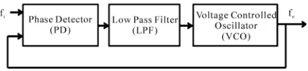
PLL is a feedback loop where a voltage controlled oscil-lator can be automatically synchronize to a periodic input signal [22-24]. The basic PLL has three components connected in a feedback loop [25-27] as shown in the block diagram of Figure 1: a voltage controlled
oscilla-tor (VCO), a phase detecoscilla-tor (PD) and a low pass filter (LPF).
The VCO is an oscillator whose frequency fosc is
pro-portional to input voltage. The voltage at the input of the VCO determines the frequency of the periodic signal at its output. The VCO output and a periodic input signal (the reference) are inputs to the phase detector. When the loop is locked on the input signal, the frequency of the VCO output is exactly equal to that of a reference. It is also said that the PLL is in the locked condition. PD produces a signal proportional to the phase difference between the reference signal and the VCO output signal. The output of the PD is altered through a low pass filter. The loop is closed by connecting the filter output to the input of the VCO. The output voltage of the filter is used to control the VCO frequency. A PLL basic property is that it attempts to maintain the frequency lock between the VCO output and reference signal even if the fre-quency of the input signal varies in time [26]. Suppose that the PLL is in the locked condition, and that the fre-quency of the incoming signal increases slightly. The phase difference between the VCO signal and the in-coming signal will begin to increase in time. As a result, the filter output voltage increases, and the VCO output frequency increases until it matches the reference fre-quency, thus keeping the PLL in the locked condition. The range of frequencies from minimal to maximal val-ues where the locked PLL remains in the locked condi-tion is called the lock range of the PLL [25-26]. If the PLL is initially locked, and input signal frequency be-comes smaller than fmin or if input signal frequency
ex-ceeds fmax, the PLL fails to keep the VCO frequency
[image:2.595.313.536.81.133.2]equal to input signal one and the PLL becomes unlocked. When the PLL is unlocked, the VCO oscillates at the
Figure 1. Bloc diagram of the PLL.
frequency fo called the center frequency, or the VCO free-running frequency. The lock can be established again if the incoming signal frequency gets close enough to fo. The range of frequencies fi = fo− fc to fi = fo + fc
such that the initially unlocked PLL becomes locked is called the capture range of the PLL [24]. The capture range 2fc depends on the characteristic of the loop filter [25]. For the used filter, an approximate implicit expres-sion for the capture range can be founded as:
0 2 2 1 c p K VDD fc f f (1)
If the capture range is much larger than the cut off fre-quency of the filter, fcfp−1 > 1, the expression for the
cap-ture range is simplified as:
0
2fc 2V K fDD p (2)
0
K is the VCO gain or the frequency sensitivity. Thanks to the rapid development of technology, the PLL is implemented using the integrated circuit systems. The most used integrated circuit is the well known 4046 chip [23].
3. System Configuration of the Drive System
and Experimental Results
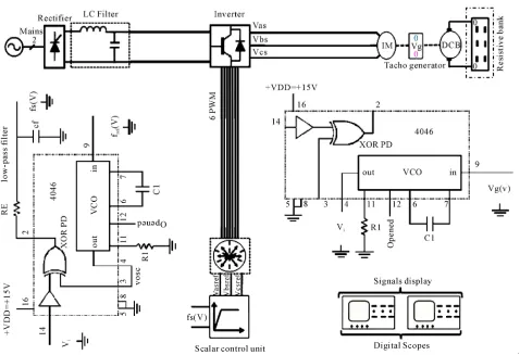
The overall system block diagram of 4046 PLL IM speed control is given in Figure 2. This system is roughly
clas-sified into two parts: the control and the power parts. The control part is consisting mainly of 4046 PLL and a sca-lar control unit. A simple positive supply voltage is needed for the chip. The positive supply voltage VDD is connected to pin 16 and the ground is connected to pin 8. The reference square wave signal goes to the input of an internal amplifier at the pin 14 of the chip. The reference signal must be a square wave with a 50% duty cycle. Therefore, to obtain this target signal, a direct voltage is fed to pin 9 (the input of the 4046 VCO) to give at its output (pin 4), a square wave signal representing the tar-get rotor speed. The VCO requires one external capacitor
C1 and one or two external resistors (R1 or R1 and R2).
Resistor R1 and capacitor C1 determine the frequency
range of the VCO and resistor R2 enables the VCO to
B. H. MOUNA ET AL. 63
Figure 2. Bloc diagram of the DPLL IM speed control.
speed is sensed by a tacho generator. The motor speed in square waveform is needed. A second 4046 is added and the motor speed in square waveform is received at its VCO output. The obtained signal is feedback at pin 3 and compared to the target frequency received at pin 4 by the phase detector (PD) [27]. The used PD in this application is the comparator I of 4046. It is simply XOR logic gate with logic down output when the two inputs are either high or both low and the logic up otherwise. The PD output is proportional to the phase error between two inputs [25-27]. The obtained PD output is then filtered by an external low pass filter [27]. The obtained filtered voltage is proportional to the synchronous (stator supply) frequency which feeds the scalar control unit. The inves-tigated DPLL IM speed regulation is built and tested using a 1kw — 2.65 A squirrel cage IM. Figure 3 shows
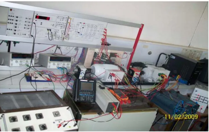
the experimental set up drive system of the hardware configuration. The IM is powered by an insulated gate bipolar transistor (IGBT) voltage source inverter (VSI). It utilizes a thyristor rectifier as a dc bus voltage link. The pulse width modulation (PWM) signals to control the power modules are generated by the scalar control card equipped with a digital processor. A tacho generator delivering 1v for 1000 rpm is mounted on the rotor shaft
to measure the rotor speed. The DPLL is built around the 4046 integrated circuit system. A DC generator (1 kw - 6.2 A) is coupled with the IM which feeds the resistor bank used as a load. Investigated system is tested for various ranges of target rotor speeds under various range of loads. For each test, the rotor speeds, waveforms of real and target speeds and the output of the LPF as con-trol signal are together illustrated. Obtained experimental results are given in Figures 4 to 18. Excellent steady
[image:4.595.316.530.338.495.2]
Figure 3. A photo of the experimental set up.
Figure 4. IM speed for a 1000rpm target speed under load appliance of 35% of its rated value.
[image:4.595.65.282.339.494.2]Figure 5. Control law for a 1000rpm target speed under load appliance of 35% of its rated value.
Figure 6. IM speed for a 1000rpm target speed under load appliance of 35% of its rated value.
[image:4.595.62.281.537.694.2] [image:4.595.314.531.538.693.2]B. H. MOUNA ET AL. 65
[image:5.595.65.281.79.246.2]Figure 8. Real and target square waveforms for a 1000rpm target speed under load appliance of 40% of its rated value.
Figure 9. Real and target square waveforms for a 400rpm target speed under load appliance of 40% of its rated value.
Figure 10. IM speed for a 400rpm target speed under load appliance of 50% of its rated value.
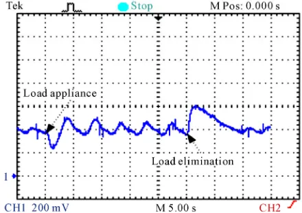
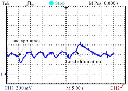
[image:5.595.309.531.288.446.2]in the locked condition. As, it is illustrated by the ob-tained experimental results under load appliance. At a time of load elimination, the square root of the stator
Figure 11. Control law for a 400rpm target speed under load appliance of 50% of its rated value.
Figure 12. Real and target square waveforms for a 400rpm target speed under load appliance of 50% of its rated value.
Figure 13. IM speed for a 400rpm target speed under load appliance of 60% of its rated value.
[image:5.595.62.283.290.446.2] [image:5.595.62.282.488.645.2] [image:5.595.309.529.490.645.2]Figure 14. Control law for a 400rpm target speed under load appliance of 60% of its rated value.
[image:6.595.315.530.80.239.2]Figure 15.Real and square waveforms for a 400rpm target speed under load appliance of 60% of its rated value.
Figure 16. IM speed for a 400rpm target frequency under load appliance of 65% of its rated value.
[image:6.595.64.282.279.435.2]the frequency of the incoming signal increases slightly. The phase difference between the VCO signal and the incoming signal will begin to decrease in time. As a re-sult, the filter output voltage decreases, and the VCO
Figure 17. Control law for a 400rpm target speed under load appliance of 65% of its rated value.
Figure 18. Real and target square waveforms for a 400rpm target speed under load appliance of 65% of its rated value.
output frequency decreases until it matches the reference frequency, thus keeping the PLL in the locked condition. As, it is illustrated by the obtained experimental results under load elimination. The digital scope screen images are illustrating the frequencies and speeds signals which are calibrated as follow: 1v for 1000rpm.
4. Conclusion
[image:6.595.314.531.281.436.2] [image:6.595.61.281.478.635.2]B. H. MOUNA ET AL. 67
is mainly provided by tackogenerator. The use of this sensor implies more electronics and high cost. To over-come these problems, a speed observer can be included in the control loop. Thanks to high performance of the PLL technique, it can be used to reconstruct the IM speed. The PLL sensorless novel scalar strategy IM speed controller will be the subject for a follow up fur-ther studies.
5. References
[1] S. Cong and Y. Liang, “PID-Like Neural Network Nonlinear Adaptive Control for Uncertain Multivariable Motion Control Systems,” IEEE Transactions on Indus-trial Electronics, Vol. 56, No. 10, October 2009, pp. 3872-3879. doi:10.1109/TIE.2009.2018433
[2] A. Rubai, M. J. Castro-Stitiriche and A. R. Ofli, “DSP Based Laboratory Implementation of Hybrid Fuzzy PID Controller Using Genetic Optimization for High Per-formance Motor Drives,” IEEE Transactions on Industry Applications, Vol. 44, No. 6, November-December 2008, pp. 1977-1986. doi:10.1109/TIA.2008.2006347
[3] M. Missiala, B. Vafakhah, J. Salmon and A. M. Knight, “Fuzzy Self-Tuning Speed Control of an Indirect Field- Oriented Control Induction Motor Drive,” IEEE Transac-tions on Industry ApplicaTransac-tions, Vol. 44, No. 6, Novem-ber-December 2008, pp. 1732-1740. doi:10.1109/TIA. 2008.2006342
[4] H. P. Huang, J. L. Yong and T. H. Chang, “Development and Fuzzy Control of a Pipe Inspection Robot,” IEEE Transactions on Industrial Electronics, Vol. 57, No. 3, March 2010, pp. 1088-1095. doi:10.1109/TIE.2009.2031 671
[5] T. Orlowska-Kowalska, M. Dybkousi and K. Szabat, “Adaptive Sliding Mode Neuro-Fuzzy Control of Two Mass Induction Motor Drive without Mechanical Sen-sors,” IEEE Transactions on Industrial Electronics, Vol. 57, 2009, pp. 553-564. doi:10.1109/TIE.2009.2036023 [6] K. Szabat, T. Orlowska-Kowalska and M. Dybkousi,
“Adaptive Sliding Mode Neuro-Fuzzy Control of Two Mass Induction Motor Drive without Mechanical Sen-sors,” IEEE Transactions on Industrial Electronics, Vol. 56, 2009, pp. 4038-4042. doi:10.1109/TIE.2009.2022514 [7] S. Katayama, K. Yubai and J. Hirai, “Iterative design of
the reduced order weight and controller for the H∞ loop
shaping method under open loop magnitude constraints for SISO systems,” IEEE Transactions on Industry Elec-tronics, Vol. 56, 2009, pp. 3854-3863. doi:10.1109/TIE. 2009.2017099
[8] K. K. Hoong, C. Y. Chung and S. Lan, “Model Based H∞
Control of Unified Power Quality Conditioner,” IEEE Transactions on Industrial Electronics, Vol. 56, 2009, pp. 2493-2504. doi:10.1109/TIE.2009.2020705
[9] I. Yalsh and U. Shaked, “Neuro adaptive H∞ Estimation
and Its Application to Improved Tracking in GPS Re-ceivers,” IEEE Transactions on Industrial Electronics, Vol. 56, 2009, pp. 642-647. doi:10.1109/TIE.2008.20083
43
[10] B. Betron, T. Ahmed-Ali and M. Benbouzid, “High Order Sliding Mode Control of Variable Speed Wind Turbines,” IEEE Transactions on Industrial Electronics, Vol. 56, No. 9, September 2009, pp. 3314-3321. doi:10.1109/TIE.2008. 2006949
[11] Y. Xinghuo and O. Kaynak, “Sliding Mode Control with Soft Computing: A Survey,” IEEE Transactions on In-dustrial Electronics, Vol. 56, No. 9, September2009, pp. 3275-3285. doi:10.1109/TIE.2009.2027531
[12] U. V. Utkin, “Sliding Mode in Control and Optimiza-tion,” Springer, Berlin, 1992.
[13] M. B. Hamed, L. Sbita and W. Abboud, “Neural Net-works for Controlled Speed Sensorless Direct Field Ori-ented Induction Motor Drives,” International Journal of Electrical Engineering, Vol. 8, No. 11, 2008, pp. 84-96. [14] L. Sbita and M. B. Hamed, “Fuzzy Controller and ANN
Speed Estimation for Induction Motor Drives,” Proceed-ing of the 4th IEEE International Conference, 2007. [15] X.-D. Sun, K.-H. Kho, B.-G. Yu and M. Matsui, “Fuzzy
Logic Based V/f Control of an Induction Motor for a DC Grid Power Leveling System Using Flywheel Energy Storage Equipment,” IEEE Transactions on Industrial Electronics, Vol. 56, 2009, pp. 3161-3168. doi:10.1109/ TIE.2009.2021679
[16] L. Y. Wang, T. Y. Chai and L. F. Zhai, “Neural Network Based Terminal Sliding Mode Control of Robotic Ma-nipulators Including Actuator Dynamics,” IEEE Transac-tions on Industrial Electronics, Vol. 56, No. 9, September 2009, pp. 3296-3304. doi:10.1109/TIE.2008.2011350 [17] M. B. Hamed and L. Sbita, “Internal Model Controller of
an ANN Speed Sensorless Controlled Induction Motor Drives,” Journal of Applied Sciences, Vol. 7, No. 11, 2007, pp. 1456-1466. doi:10.3923/jas.2007.1456.1466 [18] A. W. Moore, “Phase locked loops for motor speed
con-trol,” IEEE Spectrum, 1973, pp. 61-67. doi:10.1109/MSP EC.1973.5216851
[19] W. L. Kenly and B. K. Bose, “A Triac Speed Control of Three Phase Induction Motor with Phase Locked Loop Regulation, ” IEEE Transactions on Industrial Electron-ics, Vol. IAI-12, 1976, pp. 492-498.
[20] R. Moffat, P. Sen and R. Younker, “Digital Phase Locked Loop for Induction Motor Speed Control,” IEEE Trans-actions on Industry Applications, Vol. IAI-15, No. 2, March1979, pp. 176-182. doi:10.1109/TIA.1979.4503634 [21] P. C. Sen and M. Macdonald, “Stability Analysis of
In-duction Motor Drives Using Phase Locked Loop Control System,” IEEE Transactions on Industrial Electronics, Vol. IECI-27, No. 3, August 1980, pp. 147-155. doi:10. 1109/TIECI.1980.351668
[22] N. M. H. Ismail and M. Othman, “Low Power Phase Locked Loop Frequency Synthesizer for 2.4 GHz Band Zigbee,” American Journal of Engineering and Applied Sciences, Vol. 2, 2009, pp. 337-343. doi:10.3844/ajeassp. 2009.337.343
Electronics, Vol. 43, No. 6, December 1996, pp. 609-615. doi:10.1109/41.544547
[24] A. Takano, “Quick-Response Torque-Controlled Induc-tion Motor Drives Using Phase-Locked Loop Speed Con-trol with Disturbance Compensation,” IEEE Transactions on Industrial Electronics, Vol. 43, No. 6, December 1996, pp. 640-646. doi:10.1109/41.544551
[25] R. A. Al-Taha and S. R. Jassim, “Stability analysis of a
linear discrete data induction motor drive using phase locked loop (PLL),” Proceedings SSD Conference, 2005. [26] T. Lagutere, “Conceptions et modélisations d’oscillateurs et de leurs boucles verrouillage de phase associes pour des applications de radiocommunications mobiles profe- ssionnelles,” Ph.D. Dissertation, Poitier University, 2008. [27] H. Y. Aleksandar, “Test Generator for Examination of