Abstract—Wear and simulator testing are complicated tasks. Controlled wear testing should not be routinely done to qualify a material, but rather to elucidate wear mechanisms. It, generally, may be described as a machine used to test a joint replacement under conditions approximating those occurring in the human body. Simulator tests, on the other hand, can be used to conduct accelerated protocols that replicate/simulate particularly extreme conditions, thereby establishing the limits of performance for the material. The present paper is dealing with the study of the most common simulators, and the design of a new one that has been analysed by a CAD software to meet the aforementioned study and the ISO 14242 Standard recommendations.
Index Terms—Hip Joint Simulator, ISO 14242, flexion,
adduction, outwards rotation
I. INTRODUCTION
HE mammalian synovial joint is truly a remarkable structure and mechanism. After maturation, guided both by a genetic blueprint and by functionally driven adaptation, its behavior exceeds that of all simple engineered bearings; it is self-lubricating and, to a degree, self-repairing and capable of a service life exceeding 75 years. However, when damaged by trauma, disease or extended use, its repair and replacement has proven to be both one of the most challenging and rewarding of all aspects of human medicine. For when a painful joint, especially in the lower limb, is successfully replaced, the patient has not simply had pain relieved but has been restored to full life, often to such an extent that the permanent presence of an implant is essentially forgotten [1]. During the last decades, hip – joint endoprosthetics have been ever more widely used in the world’s orthopedic practice; more than 400,000 operations are performed every year and more than 100 types of endoprosthetic construction have been designed [2].
The biomaterials of hip joint prosthesis are metal or ceramic in femoral head, and metal, ceramic or UHMWPE in acetabular cup. Material selection and component design are important factors in the performance and durability of total joint replacements. Wear of total hip prosthesis is a significant clinical problem, because the wear of the implant products can cause adverse tissue reaction that may lead to massive bone loss around the implant and, consequently, loosening of the fixation. The need for systematic study of
N. I. Galanis is with the National Technical University of Athens, Athens, Greece (corresponding author to provide phone: +302102510174; fax: +302102580365; e-mail: [email protected]).
D. E. Manolakos is with the National Technical University of Athens, Athens, Greece (e-mail: [email protected]).
wear is evident in order to improve the knowledge of the tribology characteristics of a hip joint prosthesis. The study of wear rate typical of joint pairing constitutes an important aspect in pre-clinical validation of prosthesis. Generally, two categories of laboratory tests are conducted: wear screening device (quick tests) that provide information exclusively on the intrinsic features of the materials studied, and those conducted on joint simulators, in which real prostheses are tested in an environment that simulates physiological conditions. A wear-screening device basically uses a very simple specimen configuration. This category of tests are quick and provide information exclusively on the intrinsic features of the materials studied, without reproducing either the features of the shape of the implant, or the environment with which it will have to interact. Simulators are more complex and vary in their level of sophistication to reproduce with major accuracy the in vivo conditions [3].
Since 2000, the International Organization for Standardization (ISO) developed an international procedure in order to obtain comparable results between the laboratories. These international recommendations suggested the specifications and the methods to assess the wear and as to conduct a wear test.
In this paper it will be presented the procedure of designing such a simulator according to the strict ISO 14242, in order to adjust it in an existing automated dynamic Instron® Press, for controlling the load exerted on the examined implant. The design has to do with the simulation of the human movement, because it is complicated for femoral heads, as it has to do with the angles of flexion and extension, adduction and abduction, inwards and outwards rotation.
II. HIPSIMULATORSTUDY
Hip simulator studies have become an efficient tool for basic research as well as for preclinical testing to minimize patients’ risk when receiving new implant types. The history of simulator development, mainly driven by research, has led to the development of many diverse designs. Natural joint kinematics are more closely simulated by three-axes machines, performing independently controlled motion vectors, than by forerunner single-axis machines, executing purely flexion/extension movement. Besides the kinematics and loading regime used, the composition of test fluid still varies between the laboratories [4].
The objective of wear evaluation is to determine the wear rate and its dependence on the test conditions, which include load, speed, temperature, and the spatial configuration of the sliding components. In order to obtain realistic results, a wear test must be performed in a way to reproduce in vivo
Design of a Hip Joint Simulator According to
the ISO 14242
Nikolaos I. Galanis, Member, IAENG and Dimitrios E. Manolakos
working conditions as closely as possible. The extent to which the physiological phenomena can be reproduced by a given simulator design depends upon the availability of physiological data, the skill of the designer, and the budget for the project. The design of a hip joint simulator must consider the problem of generating relative motion cycles between two articulating surfaces, while applying a contact force that varies in magnitude and direction during the walk cycle. In addition to these mechanical features, it should also duplicate the thermo-chemical environment provided by physiological fluids [5].
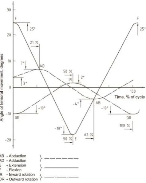
[image:2.595.51.289.251.549.2]The motion of the simulators is strict defined in the directions of all angles, like flexion and extension, adduction and abduction, inwards and outwards rotation, through ISO 14242. In Fig. 1, it is shown a diagram of variation with time of angular movement to be applied to the femoral test specimen.
Fig 1: Variation with time of angular movement to be applied to the femoral test specimen
In the last years, a lot of simulators design, were developed in order to achieve similarity between the simulation and in-vivo conditions. At this point, so as to understand them, there is a small presentation of the most known simulation in the literature, with characteristics as shown in Table I.
Typical devices of these hip joint simulators are shown in Fig. 2. According to Table I, each simulator has 2 or 3 axis of revolution with which achieves the rotation of specific angles in a variety of degrees.
The AMTI-Boston Hip Simulator simulates hip motion with simultaneous loading in a physiologic environment (Fig. 2a). The simulator provides rotation about 3 axes in
The electromechanical motion consists of flexion-extension (FE) and abduction-adduction (AA) of the femoral component. Saikko introduced a useful way to compare the wear produced in vivo and in vitro by wear simulators, by using a wear factor. The idea of the wear factor is that the wear rate is proportioned with respect to load and sliding distances [6 - 7]. Furthermore, the design of such a simulator, performed through a comparative analysis, consists a valuable basis for studies on the relationship between the types of multidirectional motion and wears [8].
The Mark II Durham hip joint simulator (Fig. 2c) is a five stations machine where the joints are mounted anatomically and subjected to a dynamic loading cycle with independent two-axis motion.
The Leeds PA II hip joint simulator (Fig. 2d) possesses six stations. The load is applied in the vertical direction and the simulator can control, independently, the Flexion-Extension and Internal-External rotations, with simplified cycles to generate a multidirectional motion between the femoral head and the acetabular cup. The joint bearings are mounted in the anatomical position with both the femoral stem and the acetabular cup cemented into metallic holders. The motions can be applied as smooth sinusoidal cycles with the flexion/extension applied to the femoral components with amplitudes of +30o/−15o, and a ±10o internal/external rotation. The internal/external rotation was applied 90ο out of phase with the flexion/extension such that
an open elliptical wear path can be generated between the components. This has been shown to give results similar to hip simulators with three physiological axes of motion; see also [3] and [9].
The ProSim Limited hip joint simulator has 10 stations (Fig. 2e). In each station, the cup is mounted in the anatomical position above the femoral head inclined at an angle of 35° with respect to the horizontal plane. This position replicates the inclination of the cup in the pelvis at 45° to the vertical and the resultant load vector 10° medially. Each station has two degree of freedom and the range of motion vary between –30° to +30°. The load and motion kinematics follows the Paul’s studies [10]. To evaluate this simulator there were a number of studies so as to examine the role of the materials of implants [11] and the design of their shape [12].
The MATCO hip simulator (model EW08 MMED) is configured in two bank of eight channel each (Fig. 2f). The cups and the heads are mounted in non-anatomical position. This simulator involves a symmetrical shift of the cup over a stationary head through a range of about 45° (±22.5°) in both sagittal and frontal planes with no rotation in the transverse plane. Usually the imposed load follows a Paul’s curve with a peak load of 2.1 kN.
The Shore Western Hip joint simulator is a 12 station machine (Fig. 2g). In each station the implants are mounted in non-anatomical position and the heads alignment is provided by a ball bearing on the head holder. In each station the implants were mounted in non-anatomical position (upside down) and the cup edges were set to an angle of about 23ο related to the horizontal plane [13].
Table I: Main characteristics between different simulators design [3].
AUTHOR SIMULATOR STATION
CLASSIFI-CATION
MOTION SIMULATED
WEAR RATE POSITION-
HEAD
Bragdon et. al.
(2003) AMTI 12 3 - axis
FE(±25ο),AA(±9ο)
IN-EX(±20ο) 4.8±1.1 mg/Mc anatomical
Saikko (2005) HUT-4 12 2-axis FE(46ο),AA(12ο) 8.2 mg/Mc anatomical
Smith
(2001) Mark II Durham 5 2-axis
FE(+30ο/-15ο)
IN-EX(±10ο) 50.32±7.07 mm3/Mc anatomical
Nevelos
(2001) Leeds PA II 6 2-axis
FE(+30ο/-15ο)
IN-EX(±10ο) 0.11±0.04 mm3/Mc anatomical
Barbour
(2000) PROSIM Limited 10 2-axis BI-AX (±30
ο) 42±1 mm3/Mc anatomical
McKellop (2004)
EW08
MMED 16 2-axis
FE(±22.5ο)
AA(±22.5ο) 0.4 mm3/Mc No anatomical
Clarke
(2005) SW 12 2-axis BI-AX (±23ο)
0.032±0.028
mg/Mc No anatomical Affatato
(2006) SW 12 2-axis BI-AX (±23ο) 0.17 mg/Mc No anatomical
FE = flexion-extension, AA = abduction-adduction, IN-EX = internal-external rotation, BI-AX = biaxial rocking, Mc = million cycles
III. DESIGN OF HIP SIMULATOR
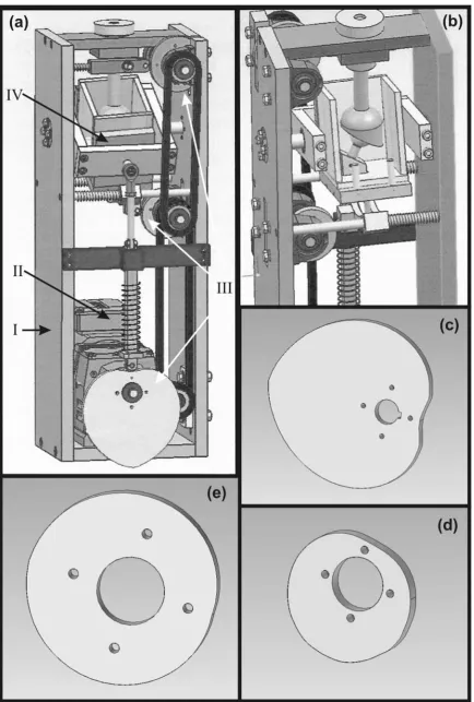
The main characteristics of the above-presented testing machines along with the recommendations of the ISO 14242 standard have been taken into consideration for designing a new concept of a 3-axis hip simulator, which will be capable to combine movements/rotations in the three important angles. The whole design was performed by using a CAD software at the Laboratory of Manufacturing Technology of the National Technical University of Athens. According to the limitations, which the specific machine has to fit in an existing automated Instron® press so as to control the amount of load that acts on implants during the study, the maximum height of simulator has not to exceed 1m. Furthermore, it must be foreseen a space for the motor, which will give rotation to the eccentric sheave of each axis, as well as a tank, filled with a fluid representing the environment inside the human body, where the implant will be immersed in.
Following the limitations arisen, we conducted at the design concept as shown in Fig. 3. The testing machine proposed herewith is consisting of four basic sets of parts, as listed below:
The main body of the simulator (I)
The electrical motor for rotating the eccentric sheaves through a system of driving chain and gear chain (II) 3 eccentric sheaves (III), one for each axis of
movement, which give motion to the tank
The tank for immersing the implant, filled with a special fluid, which simulates the physiologic phenomena (IV)
The eccentric sheaves play the most important role in this mechanism, since they are mainly charged to reproduce the exact rotation of a human hip joint, under walking conditions, according to ISO 14242 recommendations. This complex movement is described in Fig. 1, and its values permit the calculation of the exact radius of sheaves at each point of their periphery.
A. Extension and Flexion Eccentric Sheave
point at -17ο, which corresponds to the 50% of the sheave
rotation. Afterwards, an upward movement follows up to the upper point at +25ο. Taking into consideration the
movement limitations, the distance of 150mm between tank and sheave and the sheave radius of 105mm, the exact radius at each point of the sheave periphery may be calculated, as shown in the graph of Fig. 4
B. Abduction and Adduction Eccentric Sheave
The abduction and adduction movement takes place between the angles of +7ο and -7ο. The movement starts at
an angle of 3ο and gradually rotates up to the upper point of
+7ο, corresponding to the 21% of sheave rotation. A
downwards movement follows up to the lower point of -7ο,
corresponding to the 62% of the sheave rotation, and, finally, an upwards movement completes the rotation at 3ο.
Taking into account all movement limitations, the tank-sheave distance of 150mm and the tank-sheave radius of 105mm, there was also calculated the exact sheave radius at each point of its periphery; see Fig. 4.
C. Inwards and Outwards Rotation Eccentric Sheave The inwards and outwards rotation movement is limited between the angles of +2ο and -10ο. The movement starts at
an angle of -10ο and gradually rotates up to the upper point
of +2ο (at the 50% of sheave rotation), lowering again
downwards up to the lower point at -10ο. Taking into
account all movement limitations, the tank-sheave distance of 60mm and the sheave radius of 60mm, there was also calculated the exact sheave radius at each point of its periphery; see Fig. 4.
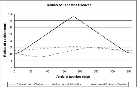
D. Radius
According to the graph in Fig. 4, the radius of the eccentric sheaves at each point is related with the angle of the movement in the specific axis and the basic radius of the part. In comparison with the graph in Fig. 1, the shape of the sheaves follows exactly the form of the angle of movement in the axis. This explains the same but in other plane, slope of the two graphs for the same rotational axis.
Fig. 4: Radius of eccentric sheaves of hip joint simulator
IV. CONCLUSION
This paper summarizes the use of hip simulators in research of new hip joint materials. Common known simulators have been presented, having one or more stations and giving the possibility to simulate the movement of a hip in 2- or 3-axis. A comparison between these machines and the recommendations of ISO 14242 lead to the design of a new one station hip simulator, with 3-axis of rotation. This movement can be achieved with the help of three individual eccentric sheaves with a specific shape, which produce the rotation in the prescribed angles according to the aforementioned international standard.
REFERENCES
[1] J. Black, Bearing Surfaces – 2005, 10th BIOLOX Symposium Proceedings, pp. 3-8, 2005
[2] N. I. Galanis and D. E. Manolakos, Investigation of Cutting Parameters in Manufacturing of Femoral heads, World Congress on Engineering 2009, pp. 1606-1611
[3] S. Affatato, W. Leardini and M. Zavalloni, Hip Joint Simulators: State of the Art, 11th BIOLOX Symposium Proceedings, pp. 171-180, 2006
[4] C Kaddick and M A Wimmer, Hip simulator wear testing according to the newly introduced standard ISO 14242, Proc Instn Mech Engrs,
Vol. 215 Part H, pp. 429-442, 2001
[5] M. Viceconti, G. Cavallotti, A.O. Andrisano and A. Toni, Discussion on the design of a hip joint simulator, Med. Eng. Phys., Vol.18 No. 3, pp. 234-240, 1996
[6] V. Saikko, T. Ahlroos, O. Calonius, A three-axis knee wear simulator with ball-on-flat contact, Wear, Vol. 249, pp. 310-315, 2001
[7] O. Calonius, V. Saikko, Force track analysis of contemporary hip simulators, Journal of Biomechanics, Vol. 36, pp. 1719–1726, 2003 [8] O. Calonius, V. Saikko, Slide track analysis of eight contemporary hip
simulator designs, Journal of Biomechanics, Vol. 35, pp. 1439–1450,
[10] A A J Goldsmith and D Dowson, Development of a ten-station, multi-axis hip joint simulator, Proc Instn Mech Engrs, Vol. 213 Part H, pp.
311-316, 1999
[11] D. Dowson, C. Hardaker, M. Flett and G. H. Isaac, A Hip Joint Simulator Study of the Performance of Metal-on-Metal Joints Part I: The Role of Materials, The Journal of Arthroplasty, Vol. 19 No. 8, pp. 118- 123, 2004
[12] D. Dowson, C. Hardaker, M. Flett and G. H. Isaac, A Hip Joint Simulator Study of the Performance of Metal-on-Metal Joints Part II: Design, The Journal of Arthroplasty, Vol. 19 No. 8, pp. 124- 130,
2004
[13] S. Affatato, M. Testoni, G. L. Cacciari, A. Toni, Mixed oxides prosthetic ceramic ball heads. Part 1: effect of the ZrO2 fraction on the
wear of ceramic on polyethylene joints, Biomaterials, Vol. 20, pp. 971-975, 1999
[14] S. Affatato, M. Spinelli, S. Squarzoni, F. Traina, A. Toni, Mixing and matching in ceramic-on-metal hip arthroplasty: An in-vitro hip simulator study, Journal of Biomechanics, Vol. 42, pp. 2439–2446,
2009
![Fig 2: Hip Joint simulators (a) AMTI, (b) HUT-4, (c) Mark II, (d) Leeds PA II, (e) ProSim Limited, (f) MATCO and (g) Shore Western [3]](https://thumb-us.123doks.com/thumbv2/123dok_us/1291698.658324/3.595.89.510.48.688/joint-simulators-leeds-prosim-limited-matco-shore-western.webp)
![Table I: Main characteristics between different simulators design [3].](https://thumb-us.123doks.com/thumbv2/123dok_us/1291698.658324/4.595.65.534.59.223/table-i-main-characteristics-different-simulators-design.webp)