Interfacial Microstructure of Silicon Carbide and Titanium Aluminide Joints
Produced by Solid-State Diffusion Bonding
Kazuyuki Tenyama
1;*, Masakatsu Maeda
2, Toshiya Shibayanagi
2and Masaaki Naka
2 1Department of Mechanical Engineering and Systems, Graduate School of Engineering, Osaka University, Ibaraki 567-0047, Japan
2Joining and Welding Research Institute, Osaka University, Ibaraki 567-0047, Japan
This paper describes the microstructure and the formation mechanism of solid-state diffusion bonded interfaces of silicon carbide (SiC) and titanium aluminide (TiAl). Two SiC specimens were diffusion bonded using a Ti-48 at%Al foil in vacuum. The interfacial microstructure has been investigated by means of scanning electron microscopy, electron probe microanalysis and X-ray diffraction. Four layers of reaction products are formed at the interface by diffusion bonding: a layer of TiC adjacent to SiC followed by a diphase layer of TiC+Ti2AlC, a layer of
Ti5Si3CXcontaining Ti2AlC particles and a layer of TiAl2. However, the TiAl2layer is formed during cooling. The actual phase sequence at the
bonding temperatures of 1573 K and 1673 K are SiC/TiC/(TiC+Ti2AlC)/(Ti5Si3CX+Ti2AlC)/Ti1XAl1þX/TiAl and SiC/TiC/(TiC+ Ti2AlC)/(Ti5Si3CX+Ti2AlC)/Ti5Al11/Ti1XAl1þX/TiAl, respectively. Ti5Al11and Ti1XAl1þXrapidly transform to TiAl2during cooling. The
layers grow obeying the parabolic law. The growth rate of the reaction layers change sensitively depending on the bonding temperature.
(Received March 29, 2004; Accepted June 11, 2004)
Keywords: solid state diffusion bonding, interfacial microstructure and reaction, titanium aluminide, silicon carbide, chemical potential diagram
1. Introduction
Turbine blades and vanes of advanced jet engines are made of nickel-based superalloys.1–4)Although these nickel-based superalloys are superb metallic materials for high-temper-ature structures, the specific densities are very high (approx-imately8:5103kg m3). Thus, the reduction of gross mass of jet engines is hard as far as the alloys are applied.5)Since
advanced aerospace structures are demanded to achieve a critical mass reduction, to replace the alloys to refractory materials with lower densities is necessary. Titanium aluminide (TiAl) is one of the candidates to replace the superalloys.5,6)The density of TiAl is3:8103kg m3, less than a half of that in nickel-based superalloys.5,7)Particularly,
the intermetallic compound with a composition slightly off-stoichiometric to the titanium-rich side, Ti-48 at%Al, per-form the most excellent mechanical properties among the intermetallic compounds in the titanium aluminide sys-tem.5–10)
To improve the thermal efficiency of jet engines, the temperature of intake-gas has to be raised. Recently, the temperature reaches 1900 K for the most advanced engines. The turbine blades and vanes can endure the temperature owing to the thermal barrier coating (TBC) and metallic bond coating (MBC). These coating techniques have to be also applied when the nickel-based superalloys are replaced by TiAl. For coating of TiAl, silicon carbide (SiC) is considered to be adequate: SiC performs higher strength, corrosion resistance and hardness at high temperatures than zirconia and NiCoCrAlY, the most commonly used TBC and MBC materials, respectively.11–13) These properties of SiC are
suitable for both TBC and MBC. Thus, the single layer of SiC functions as both TBC and MBC, making the coating process significantly simple. In addition, the density of SiC is lower than zirconia and NiCoCrAlY, being effective for mass
reduction of the jet engine components.
For practical application of TiAl and SiC, microstructures of their bond interface have to be clarified. Since the interfacial microstructure directly influences the mechanical properties of the joints, the microstructure has to be appropriately controlled to obtain the favorable performance of the joints. However, the reaction behavior between TiAl and SiC is scarcely reported.14)The knowledge is necessary
not only for precise design and control of the interfacial microstructure, but for prediction of the performance and life assessment of the joints.
The present paper reports the solid-state interfacial reaction mechanism between TiAl and SiC. The interfaces of solid-state diffusion bonded joints of SiC and Ti-48 at%Al were investigated in detail. Then, the observed reaction behavior was discussed on the basis of thermodynamics using corresponding Ti-Al-Si-C quaternary chemical potential diagram.
2. Experimental Procedure
SiC specimens were prepared from pressureless sintered columnar rods (Kyocera Corporation, SC-211) to the diam-eter and length of 6.0 and 4.0 mm, respectively. They contained a few mass percent of alumina as a sintering aid. The SiC specimens consisted of 2H, 4H and 6H polytypes.15)
The surface to be bonded was polished with 3mmdiamond paste. Ti-48 at%Al was produced by arc melting of mixed pieces of titanium and aluminum. The nominal purity for titanium and aluminum was 99.9% and 99.99%, respectively. Then, the TiAl ingots were annealed at 1273 K for 432 ks for homogenization. The ingots were cut and ground to 100-mm -thick foils under water-based lubrication. Both surfaces of TiAl foils were polished with 0.3mmalumina suspension just before the bonding treatment in order to remove surface scales. The arithmetic average roughness of SiC and TiAl surfaces was below 0.04 and 0.2mm, respectively.
*Graduate Student, Osaka University
Two SiC specimens and a TiAl foil were used for each bonding experiment. They were first washed with an ultra-sonic acetone bath. Then, the TiAl foil was inserted between two SiC specimens, and they were set in a high-frequency induction-heating vacuum furnace. The bonding temperature and time were selected from the ranges between 1573 K and 1673 K and between 0.9 ks and 32.4 ks, respectively. The vacuum inside the furnace was kept below1:5103Pa. A uniaxial pressure of 125 MPa was applied to the specimen, perpendicular to the bonding interface, during the bonding treatment. The cooling rate was set to 0.30 Ks1for the major part of bonding treatments, while it was changed within the range between 0.035 to 21 Ks1 to investigate the effect of the cooling rate on the interfacial microstructure.
The interfacial structure of the obtained joints was analyzed by scanning electron microscopy (SEM), wave-length-dispersive electron probe microanalysis (EPMA) and X-ray diffractometry (XRD). The SEM observation of the interfacial microstructures was implemented with the com-positional contrast mode of backscattered-electron images. The quantitative composition measurement by EPMA was carried out utilizing ZAF correction program.
3. Results
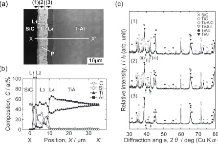
SiC and TiAl are successfully bonded to each other with all bonding conditions employed in this study. Figure 1 shows an interfacial microstructure of a SiC/TiAl joint bonded at 1573 K for 14.4 ks. Figure 1(a) is a SEM micrograph of the interface. The black region on the left side and the gray
region on the right side are SiC and TiAl, respectively. Four layered reaction products, which are marked on the micro-graph as L1, L2, L3and L4, are formed between SiC and TiAl. The thicknesses of L1, L2, L3 and L4are measured from the micrograph as 0.95mm, 0.52mm, 5.54mm and 3.51mm, respectively. L1 and L2 appear on the micrograph with a similar contrast. Small spots with a darkcontrast appearing in L1 are defects. L3 consists of two phases: the white phase appearing as the matrix and the gray granular phase, on which ‘‘P’’ is marked, dispersed in the matrix. L4 shows a homogeneous dark contrast. Figure 1(b) shows an elemental distribution profile along the line from X to X0in Fig. 1(a). L
1 and L2 consist of titanium, carbon and small amounts of aluminum and silicon. The composition of the matrix phase of L3is 35Si-9C-2Al, while that of the particle phase is Ti-25Al-25C-3Si. L4consists of titanium and aluminum, where the content of silicon and carbon is negligibly low. The content of aluminum in L4reaches 65 at%, approximately the double of that of titanium. The composition of TiAl is off-stoichiometric to the aluminum-rich side in the vicinity of the L4/TiAl interface. The composition approaches continuously the stoichiometric TiAl by leaving from the interface. Figure 1(c) shows a series of X-ray diffraction patterns which correspond to the positions (1), (2) and (3) marked on the top of Fig. 1(a). The specimen was cut at one side of SiC in the vicinity of the bond interface and polished out about 1mmfor each XRD measurement. Each reaction product and its arrangement were identified by the position of each X-ray diffraction peak and the alteration of its relative intensity. The peaks appearing in the pattern (1) are identified as SiC,15)
[image:2.595.72.518.451.747.2]TiC,16)Ti2AlC,17)Ti5Si3,18)TiAl219)and TiAl.20)Every phase formed at the interface appears in the pattern, due to the difficulty of polishing flat and parallel to the interface and the detection depth of the diffracted X-ray. However, the alteration of the relative intensity appears clearly for the peaks at 41.71, 39.55 and 42.70, which are marked with
arrows (i), (ii) and (iii), respectively. The peaks (i), (ii) and (iii) correspond solely to the 200 plane of TiC, the 106 plane of Ti2AlC and the 122 plane of Ti5Si3, respectively. In pattern (2), the peaks related to TiC do not appear. This result indicates that TiC exists only in L1 and L2. In pattern (3), only the peaks of SiC, TiAl2and TiAl appear. Therefore, L3 consists of Ti2AlC and Ti5Si3. Based on the results of SEM, EPMA and XRD, each reaction product observed at the interface is identified as follows: L1is a single-phase layer of TiC. L2 is a mixture of TiC and Ti2AlC. The matrix phase and the particle phase of L3 are Ti5Si3CX and Ti2AlC, respectively. L4is a single-phase of TiAl2. Thus, the apparent phase sequence is described as SiC/TiC/(TiC+Ti2AlC)/ (Ti5Si3CX+Ti2AlC)/TiAl2/TiAl.
In order to clarify the influence of the bonding temperature on the formation behavior of the interfacial microstructure, the interfacial microstructures of the joints bonded at 1673 K were also analyzed in the same way. Figure 2 shows a SEM micrograph of the joint interface bonded at 1673 K for 14.4 ks with the result of phase identification. The interfacial microstructures of the joints bonded at 1673 K are quite similar to those of the joints bonded at 1573 K: the interface consists of four layered reaction products. However, the interfacial microstructures of the joints bonded at 1673 K are different from those bonded at 1573 K in the following three points. The first point is that TiAl2is not formed as a layer but as acicular grains. The composition of aluminum in TiAl2 increases up to 68 at%. The second point is that raising the bonding temperature 100 K over 1573 K significantly in-creases the interfacial reaction rate. A 100-mm-thick TiAl foil is completely consumed by the reaction within 10 ks at 1673 K. The third point is that Ti2AlC is formed not only in TiC (L2) and Ti5Si3CX (L3) but also in TiAl2 (L4) by the reaction after 10 ks. Thus, the apparent phase sequence is described as SiC/TiC/(TiC+Ti2AlC)/(Ti5Si3CX+Ti2AlC)/
TiAl2/TiAl.
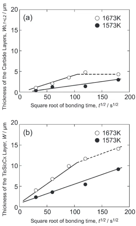
Figure 3 shows the growth behaviors of the reaction products. Figure 3(a) depicts the change in the total thickness of the TiC and TiC+Ti2AlC layers (wL1þL2) as a function of the square root of the bonding time (t1=2). The total thickness increases proportionately witht1=2, obeying the parabolic law at 1573 K. The layers initially grow obeying the parabolic law also at 1673 K. However, they stop growing after the bonding time of 10 ks, which corresponds to the time for consumption of the TiAl phase. Figure 3(b) depicts the growth behavior of the Ti5Si3CX+Ti2AlC layer. Also the Ti5Si3CX+Ti2AlC layer grows initially obeying the para-bolic law. At the bonding temperature of 1673 K, the growth is then slowed down after the consumption of TiAl phase at 10 ks. The growth rate constants of the TiC/(TiC+Ti2AlC) and the Ti5Si3CX+Ti2AlC deduced from Fig. 3 are listed in Table 1. The growth rate constants of the reaction layers at 1673 K are significantly larger than those at 1573 K. The dependence of the growth rate of each reaction layer on the bonding temperature was analyzed using an Arrhenius-type function. The frequency factor of the growth rate (k0) and the apparent activation energy for growth (Q) of the TiC/ (TiC+Ti2AlC) layers are deduced as4:3104m2s1 and
10
µ
m
Fig. 2 Interfacial microstructure of a SiC/TiAl joint bonded at 1673 K for 14.4 ks.
Fig. 3 Growth behavior of reaction phases at the interface bonded at 1573 K and 1673 K. The total thickness variations of (a) the TiC/ (TiC+Ti2AlC) layers and (b) the Ti5Si3CX+Ti2AlC layer against the
[image:3.595.312.539.67.444.2] [image:3.595.56.283.581.756.2]370 kJmol1, respectively, while those of the Ti
5Si3CX+ Ti2AlC layer are4:8107m2s1and 250 kJmol1, respec-tively. On the other hand, the interfacial microstructure is slightly influenced by the bonding temperature. Therefore, the growth rate of each layer can be effectively controlled by the bonding temperature.
4. Discussion
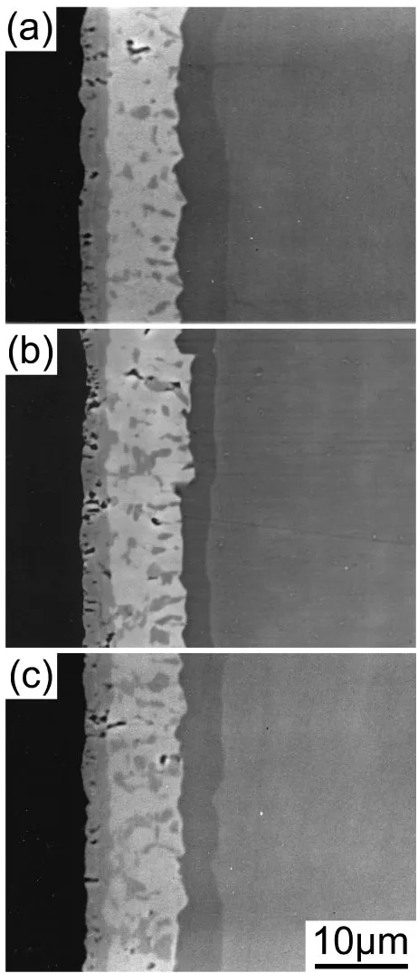
4.1 Phase sequence at the bonding temperatures The possibility of phase transformations during cooling has to be taken into account to understand the interfacial reaction at elevated temperatures. Since the analyses of the interfacial microstructures are carried out at room temper-ature, the results can be different from the actual ones at elevated temperatures. Particularly, TiAl2 is not stable at temperatures above 1488 K.21) The Ti-Al binary phase diagrams suggest that Ti1XAl1þX or Ti5Al11 are stable rather than TiAl2 at the bonding temperature of 1573 K and above.21–24) Then, the influence of the cooling rate on the formation process of the interfacial microstructures was investigated at first. Figure 4 shows the influence of the cooling rate on the interfacial microstructure of the SiC/TiAl joints bonded at 1573 K for 32.4 ks. The cooling rates of the joints depicted in Figs. 4(a), (b) and (c) are 21, 0.30 and 0.035 Ks1, respectively. The interfacial microstructures appear quite similar to each other. Only the size of the Ti2AlC particles in Ti5Si3CX appears larger with slower cooling rate, indicating that the particles grow also in the cooling process. However, no high-temperature phases of TiAl2 (e.g., Ti1XAl1þX or Ti5Al11) appear at the interfaces by changing the cooling rate. This result indicates that the transformation of the high-temperature phases to TiAl2 is completed in a considerably short time. Therefore, a higher cooling rate than 21 Ks1 is required to reveal the actual phases in the TiAl2layer at elevated temperatures. To retain joint interfaces of SiC/TiAl are, however, difficult with such high cooling rates. Thus, the further investigation has been made by quenching alloys with certain compositions corre-sponding to the phases appearing in the interfaces.
The Ti-Al alloys with aluminum composition ranging from 62.5 to 68.0 at% were heat-treated at the bonding temper-atures for 1.8 ks in vacuum and quenched in water. Figure 5 shows a series of XRD patterns taken from the quenched alloys. Ti-62.5 at%Al corresponds to the composition of TiAl in the region adjacent to TiAl2layer at the interface bonded at 1573 K. The pattern for Ti-62.5 at%Al quenched from 1573 K is shown in Fig. 5(a). The pattern indicates that TiAl20)and Ti1XAl1þX25)exist. This result agrees well with the detailed Ti-Al binary phase diagram presented by Braun and Ellner,21)indicating that the high-temperature phases are
[image:4.595.310.541.70.607.2]successfully maintained by quenching. Ti-65.5 at%Al corre-sponds to the composition of the TiAl2 layer formed at 1573 K and to that of the matrix region of TiAl2 formed at 1673 K. Figure 5(b) shows the pattern for Ti-65.5 at%Al quenched from 1673 K. Ti1XAl1þXand a small amount of h-TiAl226)are detected in the pattern. Braun and Ellner have mentioned that h-TiAl2 is a metastable phase observed only in as-cast alloys.21) Thus, the phase is considered to be a remaining phase of the as-cast alloy. Ti-68.0 at%Al corre-sponds to the composition of acicular grains of TiAl2formed Table 1 Growth rate constants of the interfacial reaction layers deduced
from Fig. 3.
Temperature, TiC/TiC+Ti2AlC layer Ti5Si3CX+Ti2AlC
T/K pffiffiffik/ms1=2 k/m2s1 pffiffiffik/ms1=2 k/m2s1
1573 1:8108 3:21016 4:9108 2:41015
1673 4:3108 1:81015 8:7108 7:61015
Fig. 4 Influence of the cooling rate on the interfacial microstructure of a SiC/TiAl joint bonded at 1573 K for 32.4 ks. (a) 21 Ks1, (b) 0.30 Ks1
[image:4.595.46.291.94.150.2]at 1673 K. Ti5Al1127) and a small amount of TiAl219) are formed in Ti-68.0 at%Al quenched from 1673 K as shown in Fig. 5(c). Since the appearance of TiAl2 is a result of phase transformation during cooling, the alloy is considered to be a single phase of Ti5Al11at the bonding temperature. Based on these results, the actual phase sequences at 1573 K and 1673 K are expressed as SiC/TiC/(TiC+Ti2AlC)/ (Ti5Si3CX+Ti2AlC)/Ti1XAl1þX/TiAl and SiC/TiC/(TiC+ Ti2AlC)/(Ti5Si3CX+Ti2AlC)/Ti5Al11/Ti1XAl1þX/TiAl, respectively.
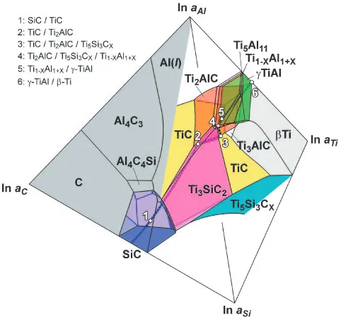
4.2 Reaction path on the chemical potential diagram The actual phase sequences at the bonding temperatures were considered from a thermodynamical point of view. Figure 6 proposes a Ti-Al-Si-C quaternary chemical potential diagram at 1573 K. The diagram is drawn on the basis of the thermodynamic data on the literature28–30)and the available
ternary phase diagrams31) with an assumption that no
quaternary equilibrium-phase is formed in the system. The diagram describes the relation between the phase equilibria and the chemical potential (i.e., the activity) of each constituent element.32) It is suitable for describing phase
sequences of diffusion-bonded interfaces.33,34)The interfacial
phase-sequence at 1573 K is described with a dotted curve on the diagram. The white plots with numbers indicate the corresponding binary and/or ternary phase equilibria on the reaction path. The point 1 corresponds to the SiC/TiC equilibrium. Between the points 1 and 2, the reaction path takes a route in the TiC region. The point 2 corresponds to the TiC/Ti2AlC equilibrium. The path between the points 2 and
3 lies on the plane of the TiC/Ti2AlC equilibrium. At the point 3, the TiC/Ti2AlC/Ti5Si3CX ternary equilibrium is achieved. The path between the points 3 and 4 is on the Ti2AlC/Ti5Si3CX binary equilibrium plane. The point 4 corresponds to the Ti2AlC/Ti5Si3CX/Ti1XAl1þX ternary equilibrium. The path between the points 4 and 5 is located in the Ti1XAl1þXsingle-phase region. The Ti1XAl1þX/TiAl equilibrium is achieved at the point 5. Then, the path goes through the TiAl region between the points 5 and 6. The point 6 corresponds to the TiAl/Ti equilibrium,i.e., the state of the Ti-48 at%Al at 1573 K. The curve of the reaction path appears continuous, suggesting that a local equilibrium is achieved at every part of the interface. Furthermore, the chemical potential of each constituent element changes monotonously from SiC toTiAl. This result indicates that the diffusion of the constituent elements at the interface can proceed smoothly by taking the reaction path. The smooth diffusion of the constituent elements is consistent with the experimental results: the reaction products grow obeying the parabolic law. Therefore, the interfacial phase sequence at 1573 K is concluded to be SiC/TiC/(TiC+Ti2AlC)/ (Ti5Si3CX+Ti2AlC)/Ti1XAl1þX/TiAl. At 1673 K, the chemical potential diagram suggests that Ti2AlC and Ti5Si3CX coexist with Ti5Al11, which is not allowed at 1573 K. This slight change in the chemical potential diagram by changing the temperature successfully explains the difference in the phase sequence between 1573 K and 1673 K: Ti5Al11 appears adjacent to the Ti5Si3CX+Ti2AlC layer instead of Ti1XAl1þX at 1673 K. Thus, the phase sequence at 1673 K being SiC/TiC/(TiC+Ti2AlC)/ (Ti5Si3CX+Ti2AlC)/Ti5Al11/Ti1XAl1þX/TiAl is consistent with the chemical potential diagram.
5. Summary
SiC was bonded to TiAl by solid-state diffusion bonding. Fig. 5 X-ray diffraction patterns from heat-treated Ti-Al binary alloys. (a)
Ti-62.5Al water-quenched from 1573 K, (b) Ti-65.5Al from 1673 K and (c) Ti-68.0Al from 1673 K.
[image:5.595.68.270.67.365.2] [image:5.595.306.547.72.296.2]The interfacial microstructure and growth behavior of the reaction products were analyzed by means of SEM, EPMA and XRD and considered on the basis of the Ti-Al-Si-C quaternary chemical potential diagram. The following points were clarified.
(1) SiC and TiAl are successfully bonded to each other with all bonding conditions employed in this study.
(2) The interfacial phase sequences of the SiC/TiAl joints appears uniformly as SiC/TiC/(TiC+Ti2AlC)/ (Ti5Si3CX+Ti2AlC)/TiAl2/TiAl at room temperature. However, the actual phase sequences at 1573 K and 1673 K are considered to be SiC/TiC/(TiC+Ti2AlC)/ (Ti5Si3CX+Ti2AlC)/Ti1XAl1þX/TiAl and SiC/TiC/ (TiC+Ti2AlC)/(Ti5Si3CX+Ti2AlC)/Ti5Al11/Ti1XAl1þX/ TiAl, respectively. Ti5Al11 and Ti1XAl1þX rapidly transform to TiAl2 during cooling.
(3) The reaction paths on the Ti-Al-Si-C quaternary chemical potential diagrams at 1573 K and 1673 K correspond with the experimental results, and the chemical potential of each interfacial phase changes monotonously from SiC to-TiAl.
(4) The reaction products grow monotonously obeying the parabolic law. The values of pre-exponential factor for the growth rate and the apparent activation energy for the growth of the carbide layers are4:3104m2s1 and 370 kJmol1, respectively, while those of the Ti5Si3CX layer are4:8107m2s1and 250 kJmol1, respectively.
REFERENCES
1) K. Yamaguchi: J. High Temperature Soc. Jpn.23(1997) 203–208, in Japanese.
2) H. Harada and T. Yokokawa: Materia Japan42(2003) 621–625, in Japanese.
3) J.-C. Zhao and J. H. Westbrook: MRS Bulletin28(2003) 622–630. 4) J. R. Nicholls: MRS Bulletin28(2003) 659–670.
5) Y. W. Kim: JOM46(1994) 30–39.
6) M. Yamaguchi: Acta Mater.48(2000) 307–322.
7) C. E. Harris and M. J. Shuart and H. R. Gray: SAMPE J.38-6 (2002)
33–43.
8) H. Inui, M. H. Oh, A. Nakamura and M. Yamaguchi: Acta Metall. Mater.40(1992) 3095–3104.
9) Y. Umakoshi, T. Nakano and T. Yamane: Scr. Metall. Mater.25(1991) 1525–1528.
10) T. Nakano, T. Kawanaka, H. Y. Yasuda and Y. Umakoshi: Mater. Sci. Eng. A194(1995) 43–51.
11) D. Baxter, A. Bellosi and F. Monteverde: J. Eur. Ceram. Soc.20(2000) 367–382.
12) Q. Fang, P. S. Sidky and M. G. Hocking: Corrosion Sci.39(1997) 511– 527.
13) S. Somiya: Mater. Chem. Phys.67(2001) 157–164. 14) H. Liu and J. Feng: J. Mater. Sci. Lett.20(2001) 815–817. 15) Powder Diffraction File, JCPDS, 29-1126, 29-1127 and 49-1428. 16) Powder Diffraction File, JCPDS, 32-1383.
17) Powder Diffraction File, JCPDS, 29-95. 18) Powder Diffraction File, JCPDS, 29-1362. 19) Powder Diffraction File, JCPDS, 47-1177. 20) Powder Diffraction File, JCPDS, 5-678.
21) J. Braun and M. Ellner: Metall. Mater. Trans. A32A(2001) 1037– 1047.
22) T. B. Massalski (Editor-in-Chief): Binary Alloy Phase Diagrams, (ASM International, Ohio, USA, 1986), pp. 173, 175 and 176. 23) J. C. Schuster and H. Ipser: Z. Metallk.81(1990) 389–396. 24) F. Stein and M. Palm:Intermetallics and Superalloys,
EUROMAT99-Volume10, D. G. Morris, S. Naka and P. Carson (eds.), (WILEY-VCH Verlag Gmbh, Weinheim, Germany, 2000) pp. 336–344.
25) Powder Diffraction File, JCPDS, 42-1137. 26) Powder Diffraction File, JCPDS, 42-1136. 27) Powder Diffraction File, JCPDS, 42-1135.
28) O. Kubaschewski, C. B. Alcock, P. J. Spencer (eds.): Materials Thermochemistry, 6th edition, (Pergamon Press, Oxford, England, 1993) pp. 257–323.
29) F. Zhang, S. L. Chen, Y. A. Chang and U. R. Kattner: Intermetallics5
(1997) 471–482.
30) P. Rogl and J. C. Schuster:Phase Diagrams of Ternary Boron Nitride and Silicon Nitride Systems, (ASM International, Ohio, USA, 1992) pp. 198–202.
31) P. Villars, A. Prince and H. Okamoto (eds.):Handbook of Ternary Alloy Phase Diagrams, (ASM International, Ohio, USA, 1995) pp. 2893–2900, 2903–2909, 4311–4319 and 7364–7366.
32) H. Yokokawa: Materia Japan35(1996) 1025–1030, in Japanese. 33) M. Maeda, R. Oomoto, T. Shibayanagi and M. Naka: Metall. Mater.
Trans. A34A(2003) 1647–1656.
34) M. Maeda, O. Igarashi, T. Shibayanagi and M. Naka: Mater. Trans.44