Enhanced Multi-Antenna Capabilities
through Small Cell Collaboration
Author:
Danny
Finn
Supervisor:
Prof. Luiz A.
DaSilva
Declaration
I declare that this thesis has not been submitted as an exercise for a degree at this or any other university and is entirely my own work.
I agree to deposit this thesis in the University’s open access institutional repository
or allow the Library to do so on my behalf, subject to Irish Copyright Legislation and Trinity College Library conditions of use and acknowledgement.
Signed:
Danny Finn
Summary
This thesis shows that collaboration between base stations in small cell scenarios can
lead to enhanced multiple-antenna gains. We demonstrate this for the case of
Multi-UserMIMO-based reassignments between adjacent small cells, from the perspectives
of spectral efficiency, energy efficiency and number of spatial layers effectively utilised.
Downlink Multi-User MIMO (MU-MIMO) is a spatial multiplexing technique in
which multiple transmit antennas at an evolved Node Base station (eNB) are used to simultaneously serve multiple User Equipments (UEs), each on a different spatial
layer, in such a way that the interference between the beams directed at
co-scheduled UEs is kept as low as possible. Due to MU-MIMO’s ability to provide
large spatial multiplexing gains without requiring additional antennas on the UE,
and its ability to overcome rank deficiency problems (which often limit single
point-to-point spatial multiplexing), MU-MIMO capabilities have been highly
emphasised in recent standardisation.
In this thesis we focus on the use of MU-MIMO in coordinated LTE small cell
networks. Small cells are an appealing technology to operators due to their low costs
of deployment and operation, and their ability to dramatically increase the spatial
reusability of limited spectrum.
MU-MIMO performs best when the antennas at the eNB experience highly
correlated channel characteristics, which is often the case in small cell scenarios.
However, for effective operation, MU-MIMO requires the channels between the base
station and different simultaneously-served UEs to be sufficiently uncorrelated (close to orthogonal) to ensure that excessive cross-layer interference is not
experienced. While this cross-layer (or multi-user) interference can be suppressed at
the transmitter using techniques such as Zero-Forcing Beam Forming, there is an
associated cost in terms of signal power, meaning that the combined throughput of
unsuppressed throughput of a single UE transmitted to on single layer alone. In
macrocell networks this problem is overcome by taking advantage of multi-user
diversity through MU-MIMO scheduling. On the other hand, in small cell scenarios where the number of UEs per cell is low, sets of UEs with mutually orthogonal
channels do not always exist in a given cell and the spatial multiplexing gains of
MU-MIMO cannot always be realised. However, due to the high density of
deployment in small cell networks, UEs are often in range of multiple small cells at
once.
For this reason, we propose MU-MIMO-based reassignments of UEs between
adjacent small cells, through which the channel orthogonality between UEs can be
increased along with the number of spatial layers which can be effectively utilised.
We propose a number of network-wide-mechanisms which target different performance objectives, such as spectral efficiency and energy efficiency, through
the use of centralised coordination between neighbouring small cells. We collectively
call these mechanismsMulti-User MIMOacross Small Cells.
This dissertation firstly reviews the background and relevant literature in the
areas of MIMO, small cells, multi-cell coordination, and cross-overs between these.
We then outline our simulation methodology and lessons learnt, including Extremely
Dense Network baseline simulator comparison and selection guidelines, and simulator
extensions implemented as part of this work. Finally, we specify, and assess the
performance of, our two MU-MIMO-based reassignment mechanisms. Performance
is assessed relative to the current practice of assigningUEs to the small cell of highest received power (not taking into account MU-MIMO considerations).
We find that from the reassignment of a single UE, the set of UEs for which
MU-MIMO is enabled achieves spectral efficiency average gains of 0.6 (from 2.16
to 2.78) and 0.7 (from 1.43 to 2.20) bps/Hz for indoor and outdoor deployments,
corresponding to the enabling of MU-MIMO for the reassignedUE on 96% and 94%
of scheduled subbands, respectively. This affected UE set for which MU-MIMO is
enabled consists of the reassigned UE and the UE with which they get paired in the
target cell. We also found that, through MU-MIMO-based reassignments, we can
Acknowledgements
Firstly and foremost, huge thanks are due to my supervisor Prof. Luiz DaSilva who
always had faith in my abilities when I thought a PhD was too big of an undertaking,
who constantly sought rigour and perfection in every aspect of my work, who instantly
knew the perfect phrasing of every key sentence, and who always went the extra mile
in making sure that CTVR was an ideal place to work.
Secondly, to Dr. Hamed Ahmadi, for working so closely with me, directing me each time I was lost, for being a huge inspiration throughout the longevity of my
PhD, and for introducing me to more people than I can remember.
And thirdly, to Dr. Andrea Cattoni, for helping to kick-start my work in the area
of MU-MIMO-based small cell reassignments which led to the main contributions
of this thesis, for constantly providing constructive feedback, for always expecting
others who work with him to (try to) work as hard as him, and for making sure that
my time in Aalborg was such a worthwhile and enjoyable experience.
My deepest of gratitude is due to the entire team at CTVR. To Prof. Linda
Doyle for being the most enthusiastic professor a department could have. To Pedro
and Francisco, for answering so many of my questions before and during the writing
of this thesis. Malandro mesmo ´e o cavalo marinho, que finge ser peixe pra n˜ao ter
que puxar carro¸ca. To Paolo, for being a true Italian. To Quentin, for being a true
French. To David for being a great student to work with. To Arman, for finding
incomprehensible ways of explaining the simplest of things. To the builders at my
window, for making sure to work just as loudly when I come in on Sunday as any other day of the week. To Emanuele, Carlo, Jonathan, Nicola, Ahmed, Seamas,
Irene, Jacek, Johann, Eamonn, Francesco, Nick, Ioannis, Jasmina, Elma, and Yong
for being great people to work and share an office with, you are all an inspiration.
To Justin, for working with me across so many years, for pushing me toward the
ever-growing close-knit team.
Thanks are due to the crews from CREW and Aalborg, as well as Rouzbeh and
Holger in Alcatel Lucent, for fruitful collaborations of which I’m sure there’ll be more to come.
To Muireann, for making thesis writing a lot less daunting.
To the Dublin University Trampoline Club, to which I will be forever indebted for
so hugely enhancing my college experience to the extent that I would almost consider
Trinity College and the Trampoline Club synonymous. The club and the people that
made it have provided 8 years of great training, great coaching, great trips away,
great competitions, great nights out, and great friends, which I will never forget.
Special mentions to Pa and Conor O’Brien, for being a great flatmate, and visiting
at just the right time, respectively.
To Bevan, Rob, Glenn, Kieron and Will for providing breaks when I needed them.
To my parents, for raising a great family and dedicating so much time to each of
us. You have made sure that there is nothing we can’t do if we put our minds to it.
To my examiners, Prof. Simon Saunders and Dr. Muhammad Ali Imran, for their
in-depth feedback which greatly strengthened the contributions of this work.
Most importantly of all, I dedicate this thesis to Fiona for keeping me focused,
bearing with me as the end approached, and always providing the best of company.
Finally, subtle thanks are due,
To the teams of red and blue.
Keepers, choppers, and shnakes,
Intensified our lunch breaks,
To the extend that they’re getting a mention too.
To Colm Madigan for highlighting the use of white text.
Finally, to anyone reading this, I nominate you for the ALS ice-bucket challenge:
Contents
Declaration i
Summary iii
Acknowledgements v
Contents vii
List of Figures xi
List of Tables xiii
1 Introduction 1
1.1 Overview . . . 1
1.2 Key Contributions . . . 4
1.2.1 MU-MIMO-based Reassignment Mechanism aimed toward Spectral Efficiency Gains . . . 4
1.2.2 Refined MU-MIMO-based Reassignment Mechanism aimed toward Energy and Spectral Efficiency Gains . . . 5
1.2.3 Extensions to Simulation Environments for Small Cell LTE Networks 7 1.3 Chapter outline. . . 7
1.4 Notation . . . 8
1.5 Publications . . . 10
1.5.1 Peer Reviewed Publications . . . 10
1.5.2 Non-Peer Reviewed Publications . . . 11
2 Background and Related Work 13 2.1 Advanced Multi-Antenna Capabilities . . . 14
2.1.2 Multi-User MIMO (MU-MIMO) . . . 21
2.1.3 Coordinated Multi-Point (CoMP) . . . 29
2.2 Advances in Small cells . . . 35
2.2.1 The Use of Multiple Antennas in Small Cells . . . 36
2.2.2 Collaboration and Supporting Network Structures. . . 38
2.2.3 Green Wireless . . . 40
2.3 Summary . . . 41
3 Simulation Methodology and Scenarios 43 3.1 Comparison of Simulators . . . 44
3.1.1 Simulator Types . . . 45
3.1.2 Supported Features . . . 48
3.1.3 Comparative Analysis . . . 54
3.2 Extensions to the Vienna SL Simulator . . . 59
3.2.1 Multi-User MIMO System Level Implementation . . . 60
3.2.2 MU-MIMO User Selection Algorithm . . . 62
3.2.3 Zero-Forcing MU-MIMO . . . 64
3.2.4 MU-MIMO CQI calculation . . . 65
3.2.5 Neighbouring eNB Feedback. . . 66
3.2.6 MU-MIMO Spectral Efficiency . . . 67
3.2.7 MMSE-IRC Filtering . . . 68
3.2.8 Reassignment . . . 68
3.3 Indoor and Outdoor Scenarios . . . 69
3.3.1 Indoor Residential Scenario . . . 70
3.3.2 Outdoor City Centre Scenario . . . 71
3.4 Summary . . . 73
4 MU-MIMO Across Small Cells: Spectral Efficiency Increases 77 4.1 Introduction . . . 77
4.2 System Model . . . 80
4.3 Reassignment Mechanism . . . 83
4.3.A Selection of Considered UEs . . . 83
4.3.B Check for Target UEs . . . 85
4.3.D Reassignment . . . 86
4.4 Simulation Results . . . 88
4.4.1 Reassignability of UEs . . . 91
4.4.2 Increases in MU-MIMO usage due to UE reassignments . . . 94
4.4.3 Increases in Spectral Efficiency due to UE Reassignments . . . . 99
4.4.4 Time Scale Considerations . . . 104
4.5 Summary . . . 106
5 MU-MIMO Across Small Cells: Energy and Spectral Efficiency Increases107 5.1 Introduction . . . 107
5.2 System Model . . . 111
5.3 Reassignment Mechanism . . . 113
5.3.A Selection of Considered UEs . . . 113
5.3.B Check for Target UEs . . . 115
5.3.C Selection of UEs to reassign from the Reassignable Set . . . 115
5.3.D Reassignment . . . 116
5.3.E Deactivation of emptied small cells . . . 116
5.4 Simulation Results . . . 117
5.4.1 Energy Efficiency Gains . . . 118
5.4.2 Increases in Spectral Efficiency . . . 123
5.4.3 Discussion of Other Potential Baselines . . . 126
5.5 Summary . . . 129
6 Conclusions and Future Work 131 6.1 Contributions and Findings . . . 131
6.2 Future Work . . . 134
6.2.1 Investigation of Additional Baselines for Ch5 Comparison. . . 134
6.2.2 Dynamic Investigation of Ch5’s Long-term Performance . . . 135
6.2.3 Variation of Tx Power with Small Cell Density . . . 135
6.2.4 Coordinated Reassignments between MEA-equipped Small Cells . 135 6.2.5 Making Simulator Code Available . . . 136
6.2.6 Combined MU-MIMO Across Small Cells and CS-CoMP . . . 136
List of Figures
1.1 MU-MIMO-based reassignment example. . . 4
1.2 Example outcome of reassignment resulting in small cell sleep state usage. . . 6
2.1 Downlink Multi-antenna transmission techniques. . . 14
2.2 Single-User MIMO transmission. . . 16
2.3 Comparison of SU-MIMO transmissions modes at UE speed of 3kmph. . . 18
2.4 Comparison of SU-MIMO transmissions modes at UE speed of 120kmph. . . 19
2.5 LTE Release 8 single-layer codebook beams for 4 Tx antenna uniform linear array. 20 2.6 Multi-User MIMO transmission. . . 22
2.7 Percentage throughput gain from using MU-MIMO over SU-MIMO. . . 23
2.8 Correlations between LTE Rel.8 codebook 4 Tx single-layer precoding vectors.. . 24
2.9 ZFBF 2×1 computational complexity comparison of MU-MIMO schedulers. . . 27
2.10 ZFBF 2×1 spectral efficiency comparison of MU-MIMO scheduling algorithms. . 28
2.11 CoMP transmission Types. . . 30
2.12 LTE-A Downlink Reference Signal Structure for 2 Tx antenna configuration. . . 33
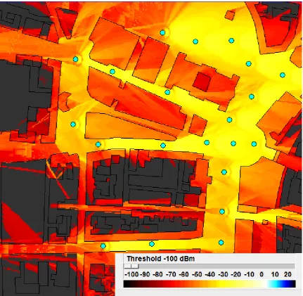
3.1 SINR distribution in an extremely dense heterogeneous deployment. . . 45
3.2 Mapping between simulator types and LTE protocol stack layers. . . 46
3.3 Curves used for mapping Effective SINR to BLER for a given CQI. . . 49
3.4 Variation in simulation time with small cell deployment density. . . 57
3.5 Dual Stripe indoor femtocell deployment scenario. . . 70
3.6 3-cell Munich outdoor picocell deployment scenario . . . 72
3.7 21-cell Munich outdoor picocell deployment scenario. . . 74
4.1 Spectral Efficiency-based MU-MIMO Across Small Cells reassignment process . . 84
4.2 Spectral efficiency reassignment gains for varying ∆M U I. . . 88
4.3 Reassignment Explanatory Example. . . 91
4.5 Increases in Multi-User MIMO usage resulting from reassignment. . . 96
4.6 Multi-User MIMO Usage Before and After Reassignment. . . 97
4.7 Increases in Multi-User MIMO usage resulting from reassignment for different DRs 98 4.8 Increases in Spectral Efficiency resulting from reassignment. . . 100
4.9 Spectral Efficiency Before and After Reassignment. . . 101
4.10 Increases in Spectral Efficiency resulting from reassignment for different DRs. . . 102
4.11 Spectral Efficiency Before and After Reassignment for different DRs. . . 103
4.12 MU-MIMO usage resulting from reassignment for different time periods. . . 105
5.1 Small cell deactivation after MU-MIMO-based small cell reassignments. . . 110
5.2 MU-MIMO Across Small Cells with sleep mode usage mechanism. . . 112
5.3 Percentage of eNBs that can be deactivated. . . 120
5.4 Reduction in power consumption. . . 122
5.5 Deactivated eNBs for Greedy heuristic and Optimal reassignment selection. . . . 123
5.6 Increases in Spectral Efficiency resulting from reassignment. . . 124
List of Tables
3.1 Ease-of-use Metric/Indicators . . . 54
3.2 Simulation Parameters and Hardware Configuration . . . 58
3.3 SINRs used in MU-MIMO Simulation (single cell implementation) . . 61
4.1 Simulation parameters . . . 92
4.2 Cell reassignment observations . . . 94
5.1 Simulation parameters . . . 119
1
Introduction
This thesis shows that simple collaboration between base stations in small cell
scenarios can lead to enhanced multiple-antenna gains. We demonstrate this for the
case of Multi-User MIMO-based reassignments between adjacent small cells, from
the perspectives of spectral efficiency, energy efficiency and number of spatial layers
effectively utilised.
1.1
Overview
The use of multiple antennas in cellular systems (also known as Multiple Input
Multiple Output (MIMO)) has recently led to significant gains in capacity and is commonly considered the key technological advance to which the transition from
3G to 4G was attributed. These gains come in three main forms: diversity,
beamforming, and spatial multiplexing. Diversity gains improve the robustness of a
link by transmitting and/or receiving different versions of the same signal over
multiple antennas. Beamforming gains are obtained by applying complex weights to
closely-spaced antennas in order to produce constructive and destructive
interference in desired directions, hence boosting the Signal to Interference and
Noise Ratio (SINR). Spatial multiplexing takes advantage of multipath fading
effects between multiple Transmit (Tx) and Receive (Rx) antennas to simultaneously transmit multiple spatial streams which can be successfully
separated at the receive side; in this way the throughput can be greatly elevated
through the usage of an increased number of independent data streams. Of these,
spatial multiplexing has attracted the most interest due to its ability to boost
Rx antennas nr.
This spatial multiplexing operation is not ideal, though, as correlations between
the paths of different Tx-Rx pairs can lead to what are known as rank deficiencies,
in which it is not possible to distinguish between transmissions on different spatial
layers, leading to a reduction in throughput. Further, while it is often possible to scale up the number of transmit antennas at the base station side, due to the small
form factor of the average mobile device, the housing of many antennas at the User
Equipment (UE) side is more difficult. This can, in turn, limit the number of spatial
layers available.
For these reasons there has been a recent shift in emphasis from spatial
multiplexing on a single link between a base station and aUE, to what is known as
Multi-User MIMO (MU-MIMO) [1], this was also forecasted in [2]. In MU-MIMO,
instead of serving a single UE on multiple spatial layers, multiple UEs are each
served on a single spatial layer, which is significantly less susceptible to rank
deficiencies and allows the capacity to instead increase to the order of
min(nt,PKk=1nr,k), where k ∈ {1, . . . , K} are the simultaneously served UEs within
the cell. Essentially this consists of performing beamforming toward multiple
spatially distinct UEs at once in such a way that the interference between the
beams directed at co-scheduled UEs is kept as low as possible.
In this thesis we focus on the use of MU-MIMO in coordinated Long Term
Evolution (LTE) small cell networks. Small cell infrastructure has recently seen
massive growth in deployment with the number worldwide currently exceeding 8.4
million [3] (compared to roughly 6 million macrocells [4]). This is a very appealing
technology to operators due to its low cost of deployment and operation compared
to macrocell base stations, and its ability to dramatically increase the spatial
reusability of limited spectrum.
MU-MIMO works best when the antennas at the base station experience highly
correlated channel characteristics [2, Fig.4]; as high antenna correlation is often
observed in cases where antennas are closely spaced this suits the small form factor of small cell devices. Further, due to strong line-of-sight components and reduced
scattering in small cell scenarios compared to macrocell cases [5], spatial
multiplexing on a single base sation-to-UE link would be subject to regular rank
deficiencies. MU-MIMO does however, for effective operation, require that the
sufficiently uncorrelated (close to orthogonal) to ensure that excessive cross-layer
interference is not experienced. While this cross-layer or multi-user interference can
be suppressed at the transmitter using techniques such as Zero-Forcing Beam Forming (ZFBF), there is an associated cost in terms of signal power, meaning that
the combined throughput of the spatial layers of multiple non-orthogonal UEs may
be less than the unsuppressed throughput of a single UE transmitted to on single
layer alone. In macrocell networks this problem is overcome by taking advantage of
multi-user diversity through MU-MIMO scheduling. In other words, as macrocells
contain many UEs, user selection can ensure that sets of UEs with mutually
orthogonal channels are always scheduled together. On the other hand, in small cell
scenarios where the number of UEs per cell is low, sets of UEs with mutually
orthogonal channels do not always exist in a given cell and the additional spatial multiplexing gains obtained for MU-MIMO cannot always be realised. At the same
time, due the high density of deployment in small cell networks, UEs are often in
range of multiple small cells at once.
For this reason we investigate the reassignment of UEs between adjacent small
cells to increase both the channel orthogonality between the UEs of each cell in the
small cell network and the number of spatial layers which can be effectively utilised.
We propose a number of network-wide-mechanisms which target different performance objectives through the use of centralised coordination between
neighbouring small cells. These objectives include increases in spectral efficiency
and reductions in small cell network energy consumption through combined use of
MU-MIMO-based reassignments and small cell sleep states. We collectively call
these mechanisms Multi-User MIMO across Small Cells.
In investigating our proposed Multi-User MIMO across Small Cells mechanisms
we compare to a primary baseline of Reference Signal Received Power (RSRP)-based cell association. This represents the default association policyLTEsystems [6, Section
5.2.3] and, in cases where all evolved Node Base stations (eNBs) operate within the
same frequency and have the same multi-antenna capabilities, this is the association
eNB 1
eNB 2
eNB 3
UE 2
PMI = 9
UE 3
PMI = 10
UE 1
PMI = 1
[image:20.595.63.486.97.324.2]UE 4
PMI = 5
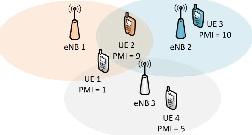
Figure 1.1: MU-MIMO-based reassignment example. UE colours indicate the small cell base station to which eachUEis initially attached.
1.2
Key Contributions
In devising new methods to enhance downlink multi-antenna transmission capabilities
through small cell collaboration the following primary contributions are made:
1.2.1
MU-MIMO
-based Reassignment Mechanism aimed toward
Spectral Efficiency Gains
This contribution centres on the proposal and assessment of the Multi-User MIMO
across Small Cells concept, from the perspective of spectral efficiency gains. As
already stated, MU-MIMO is the spatial multiplexing of data streams to multiple
UEs, each on different spatial layers, which can considerably increase UE spectral efficiencies. In small cell networks, where the number of UEs per cell is low, finding
suitable sets of UEs to be co-scheduled for MU-MIMO is not always possible. In
these cases we propose MU-MIMO-based cell reassignments of UEs into adjacent
cells to engineer a scenario in which the number of sets ofUEs with relative channels
this new concept for realistic indoor and outdoor small cell scenarios, taking into
account user scheduling before and after the reassignment occurs. From system level
simulations we show that the proposed mechanism results in considerable increases in spectral efficiency andMU-MIMO usage by both the reassignedUEand theUEin
the target cell with which it gets paired. We also show that, in the outdoor small cell
scenario, the percentage of UEs that meet the reassignment criteria and can benefit
from neighbour-cellMU-MIMO is almost double that of the indoor scenario.
In this contribution the emphasis is purely on increased spectral efficiency. Let
us consider the simple scenario shown in Figure 1.1 where UE colours indicate the
small cell eNBs to which the UEs are initially attached and the marked Precoding
Matrix Indicator (PMI) of each UE indicates a fed-back quantised form of the
channel directionality of each eNB-to-UE link. To simplify explanation, this figure
assumes that the PMI of each UE stays the same regardless of which eNB it is
served by; in reality, the channels from different eNBs are likely to instead correspond to different PMIs. As will be illustrated later in Figure 2.8 the channel
codeword corresponding to PMI=9 is orthogonal to those of both PMI=1 and
PMI=10, while other PMI codeword combinations are not orthogonal. Assuming
that only UEs with orthogonal quantised channels can be co-scheduled for
MU-MIMO, MU-MIMO cannot be performed in any small cell in this configuration.
However, by reassigning eitherUE1 toeNB 1 or UE 2 toeNB 2, assuming that UE
SINRs after reassignment are sufficiently high in both cases, previously unrealisable
MU-MIMO spatial multiplexing gains can be obtained.
1.2.2
Refined
MU-MIMO
-based
Reassignment
Mechanism
aimed toward Energy and Spectral Efficiency Gains
In this contribution we investigate the reassignment of UEs between adjacent small
cells to concurrently enable spatial multiplexing gains through MU-MIMO and reductions in energy consumption though switching emptied small cells to a sleep
state. As before, UEs can be reassigned between adjacent small cells provided that
the resulting UE-to-base station assignment corresponds to increased mutual
orthogonality between the UEs served within each cell and a minimum expected
eNB 1
eNB 2
eNB 3
UE 2
PMI = 9
UE 3
PMI = 10
UE 1
PMI = 1
UE 4
PMI = 5
Z
Z
Z
Given UE 2 is being reassigned from eNB 1 to eNB 2:
Original eNB:
eNB 1 Reassigned UE (RUE):
UE 2
Target eNB:
eNB 2 Target UE (TUE): UE 3 (PMI 10
^
PMI 9)
Figure 1.2: Example outcome of reassignment resulting in small cell sleep state usage.
configuration. We formulate the selection decision of which UEs to reassign as a set
covering problem with the objective of maximising the number of small cell base
stations to switch to a sleep state. Our results show that, for both indoor and
outdoor LTE small cell scenarios, the proposedMU-MIMO-based reassignments can
achieve significant reductions in the required number of active small cell base
stations, whilst simultaneously achieving increases in spectral efficiency of the
affected UE set for which MU-MIMO is enabled (i.e. the set of the reassigned UE
and the target UE with which they get paired in the target cell).
Returning to the example in Figure 1.1, two possible reassignments exist, both
of which result in a configuration better suited to MU-MIMO spatial multiplexing
gains. These are the reassignment of UE1 to eNB1 and the reassignment of UE2 to
eNB2. It is also the case that performing both reassignments does not make sense as if UE2 is reassigned to eNB2 then it cannot perform MU-MIMO withUE1 ineNB1,
as each UE can only be attached to a single eNB. In the previous mechanism the
decision of which of these two reassignments to perform was based purely on which of
the two reassignments results in the greatest expected spectral efficiency increase for
to the reassignment ofUE2 toeNB2 as this results in the emptying ofeNB1. If there
are no longer any UEs attached to eNB1 it can be switched to a sleep state and in
doing so both conserve energy and reduce interference to theUEs in the neighbouring cells. This is illustrated in Figure1.2.
1.2.3
Extensions to Simulation Environments for Small Cell
LTE
Networks
In the course of implementing the two above investigations for system-level simulation
a number of contributions from the point of view of simulation methodology were
made. In order to assist others in the simulation of Extremely Dense Networks
(EDNs) we identify and compare a representative cross-sectional set of potential
EDN simulators and put forward guidelines to steer readers toward the selection of
the appropriate simulator for their desired investigation. Further, in the context of
the Vienna System Level (SL) simulator [8], which we have selected as the baseline
simulator for our investigations, a number of extensions are required in order to
assess our desired scenarios. These extensions include, but are not limited to, the
implementation of MU-MIMO at system level, MU-MIMO scheduling and channel
quality estimation, and the inclusion of indoor and outdoor small cell scenarios. We
provide discussion of the extensions performed and how they are carried out, and we
will make some of these extensions available to the wider community so that they may be built upon by others.
1.3
Chapter outline
The remainder of the thesis is organised as follows:
As our work considers the reassignment of UEs between adjacent small cells to achieve increased multi-antenna gains,Chapter2focuses on providing background on
the state of the art in the fields of advanced multi-antenna techniques and small cell
deployments, including a discussion of multi-cell coordination within both contexts,
how the two fields cross over, and, in the case of small cells, how they can be advanced
To assess the potential gains of our proposed reassignment mechanisms it is
essential to be able to simulate their performance in the context of realistic
scenarios. How we go about this is the subject matter of Chapter 3. We provide a comparative analysis of simulation tools suitable for densely deployed small cell
network investigations and compile guidelines for others wanting to select an
appropriate simulation environment. Based on this comparison, for our
investigations we take as a baseline the Vienna LTE SL Simulator. We then
identify, implement, and detail the required extensions to this simulation
environment for our investigated case.
Chapter4focuses on our contributions obtained from theMU-MIMOAcross Small Cells reassignment mechanism, primarily from the perspectives of spectral efficiency
andMU-MIMOspatial multiplexing gains. The performance of ourMU-MIMO-based
reassignment mechanism is assessed in both realistic indoor and outdoor environments
and with varying deployment densities.
Chapter 5 extends the work of Chapter 4 by also considering the application of
small cell sleep states to reduce the amount of energy consumed by the small cell
network. In order to maximise the number of small cells switched to a sleep state while ensuring that reassignments result in an increase in the reassignedUE’s spectral
efficiency, we reformulate the reassignment selection process into the form of a set
covering problem. We then present the increases in both energy and (reassigned and
target UE) spectral efficiency that are achieved from our proposed approach.
Chapter 6 concludes the work by summarising our findings and identifying a
number of directions for future work.
1.4
Notation
Throughout this thesis we apply the following conventions:
• Italic letters (e.g., h) representscalars.
• Lower case boldface letters (e.g., h) represent vectors.
• Upper case boldface letters (e.g., H) represent matrices.
Additionally, the following listed variables are used regularly:
• H, h orh denote (matrices or vectors of) channel coefficients. • x orx denote transmitted signals, before transmit precoding. • y or y denote received signals, before receive filtering.
• z or z denote received signals, after receive filtering.
• U oru denote codebook-defined fed back unitary precoders.
• W or w denote transmitted unitary precoders.
• G or g denote receive filters.
• heff denotes effective channels (product of the channel matrixH and precoding
vector w).
• C denotes covariances.
• n denotes noise.
• k and j denote user indices (general and interfering, respectively).
• e,l, O and T denote base station indices (general, interfering, serving/original and target base stations, respectively).
• b denotes the index of a Resource Block (RB)(subband).
• nM U denotes the number of users simultaneously served by a MU-MIMO
transmission, with a maximum value of NM U.
• r denotes the predicted instantaneous rate. • R denotes the long-term average rate.
• a indicates whether a small cell base station is operating in an active state.
||.||, (.)−1, (.)H, (.)T and (.)† denote the norm, inverse, conjugate (Hermitian) transpose, regular transpose and Moore-Penrose pseudo-inverse of a matrix,
1.5
Publications
Publications which relate directly to the work of this thesis are marked with a black
bullet symbol (•). Publications marked with a white bullet symbol (◦) were performed
as part of other projects during the course of this PhD.
1.5.1
Peer Reviewed Publications
Submitted
• D. Finn, H. Ahmadi, R. Razavi, H. Claussen, and L. A. DaSilva, ”Energy and Spectral Efficiency Gains From Multi-User MIMO-based Small Cell
Reassignments,” submitted to IEEE Global Communications Conference
(Globecom), 2015.
• D. Finn, H. Ahmadi, A. Cattoni, and L. A. DaSilva, ”Improved Spectral Efficiency through Multi-User MIMO Across Small Cells,” submitted to IEEE Transactions on Vehicular Technology (TVT), 2015.
• D. Finn, C. Galiotto, P. Alvarez, J. Van De Belt, H. Ahmadi, and L. A. DaSilva, ”Simulating Dense Small Cell Networks,” submitted to IEEE
Vehicular Technology Magazine, 2014.
Accepted
• D. Finn, H. Ahmadi, A. Cattoni, and L. A. DaSilva, ”Multi-User MIMO across Small Cells,” in IEEE International Conference on Communications (ICC),
Sydney, Australia, 2014.
◦ I. Macaluso, D. Finn, B. Ozgul, and L. A. DaSilva, ”Complexity of Spectrum Activity and Benefits of Reinforcement Learning for Dynamic Channel
Selection,” in IEEE Journal on Selected Areas in Communications (JSAC),
◦ P. Van Wesemael, W. Liu, M. Chwalisz, J. Tallon, D. Finn, Z. Padrah, S. Pollin, S. Bouckaert, I. Moerman, and D. Willkomm, ”Robust Distributed Sensing with
Heterogeneous Devices,” in Future Network & Mobile Summit (FNMS), Berlin, Germany, 2012.
◦ D. Finn, J. Tallon, L. A. DaSilva, S. Pollin, W. Liu, S. Bouckaert, and J. V. Gerwen, ”Experimental Assessment of Tradeoffs among Spectrum Sensing
Platforms,” Sixth ACM International Workshop on Wireless Network
Testbeds, Experimental Evaluation and Characterization (WiNTECH), Las
Vegas, Nevada, USA, 2011.
1.5.2
Non-Peer Reviewed Publications
• D. Finn, H. Ahmadi, A. F. Cattoni, and L. A. Dasilva, ”Multi-user MIMO in small cell networks with coordinated scheduling,” in 4th Workshop of COST
Action IC0902, Rome, Italy, 2013.
◦ D. Finn, L. DaSilva, and Y. Xiao, ”Playing Games in Cognitive Radio Networks,” IEEE Communications Society Multimedia Communications
Technical Committee E-Letter (COMSOC MMTC E-Letter), vol. 7, no. 6, pp.
22-25, 2012.
◦ J.-H. H. C. Heller, S. Bouckaert, I. Moermann, S. Pollin, P. v. Wesemael, D. Finn, D. Willkomm, ”A Performance Comparison of Different Spectrum
Sensing Techniques.”, Wireless Innovation Forum Conference on Wireless
Communications Technologies and Software Defined Radio
(SDR-WInnComm), 2011.
◦ L. A. Dasilva, L. Doyle, D. Finn, and J. Tallon, ”CREW: Building a Cognitive Radio Federation,” in 1st Workshop of COST Action IC0902, Bologna, Italy,
2
Background and Related Work
In this chapter we provide background and related work on two main concepts
which are central to this thesis: advanced multi-antenna techniques and small cell
deployments.
We start this by providing some background on single-cell downlink multi-antenna
concepts: what they are, how they work and what general directions the research is
going in, before moving on to coordinated multi-cell concepts and discussing how our
work ties in with these.
Next we consider small cell deployments, where we define small cell following the
definition of the Small Cell Forum [9]: ”’Small cells’ is an umbrella term for
operator-controlled, low-powered radio access nodes, including those that operate in licensed
spectrum and unlicensed carrier-grade Wi-Fi. Small cells typically have a range from
10 meters to several hundred meters. Types of small cells include femtocells, picocells
and microcells - broadly increasing in size from femtocells (the smallest) to microcells
(the largest). Any or all of these small cells can be based on ’femtocell technology’
- i.e. the collection of standards, software, open interfaces, chips and know-how
that have powered the growth of femtocells.”; however, we include Remote Radio Heads (RRHs) as a type of small cell also. In this chapter, we consider how the small
cell market is progressing, what multi-antenna techniques have been investigated for
these scenarios, what architectures are best for allowing coordination between small
cells, and finally, how further energy savings can be made in small cell green wireless
SU-MIMO
MU-MIMO
CoMP
Figure 2.1: Downlink Multi-antenna transmission techniques.
2.1
Advanced Multi-Antenna Capabilities
Multiple Input Multiple Output (MIMO) uses multiple transmit and receive
antennas to improve channel performance. In this thesis we centre our focus on
downlink multi-antenna transmissions, which, as shown in Figure 2.1, can be
broadly broken down into three main categories: Single-User MIMO (SU-MIMO),
Multi-User MIMO (MU-MIMO) and Coordinated Multi-Point (CoMP)
transmissions. These correspond, respectively, to transmissions from a single multi-antenna transmitter to a single multi-antenna receiver, transmissions from a
single multi-antenna transmitter to a multiple (either single- or multi- antenna)
receivers (each on separate spatial layers), and coordinated transmissions from
multiple transmitters to a single (or multiple) receiver(s). Within these categories a
number of sub-categorisations also exist.
In this thesis we will focus mainly on 3rd Generation Partnership
Program (3GPP) Long Term Evolution (LTE)/LTE-Advanced (LTE-A) systems;
however, the mechanism we propose could equally be applied to other radio access
technologies.
Right from its initial release in 2008, LTE standardisation has relied on the use of multiple antenna transmissions to boost system performance, supporting up to
four antennas at both the Transmit (Tx) and Receive (Rx) side and transmissions
on up to four spatial-layers. This initial release focused on SU-MIMO transmissions
and offered only basic support for MU-MIMO. Since then, increased emphasis was
transmission mode 9 and the Demodulation Reference Signal (DM-RS). As well as
enabling SU-MIMO transmissions on up to 8 spatial layers, these allowed for
flexible switching between SU-MIMO and MU-MIMO, non-codebook-based precoding and MU-MIMO spatial multiplexing of up to 4 User Equipments (UEs)
each on a single spatial layer or 2 UEs each on 2 spatial layers. Since then
MU-MIMO advances focusing on improving Channel State Information (CSI), 3D
beamforming (MU-MIMO serving multipleUEs on the elevation plane) and massive
MIMO (MU-MIMO with very large numbers of co-scheduled UEs) have been
discussed for the Release 12 [1].
CoMP functionalities were first discussed for LTE Rel.9 although it wasn’t until
Rel.11 that basic CoMP support was provided. Continuing specification efforts in
this area are primarily focused on improving multi-pointCSI feedback specification,
control channel enhancements and CoMP solutions which make use of relaxed
backhaul requirements [1].
Needless to say, the current emphasis toward multi-antenna techniques which
exploit network/system configurations (whether multiple UEs or multiple evolved
Node Base stations (eNBs)) ties in well with our own emphases within this thesis.
2.1.1
Single-User
MIMO
(
SU-MIMO
)
In an SU-MIMO general system with Nt Tx antennas and Nr,k Rx antennas,
performed over NL spatial layers, the Nr,k×1 received signal of UE k, yk, can be
represented as follows
yk= Hk,Odk
| {z }
Desired Signal
+
NeN B−1 X
l=1
alHk,ldl
| {z }
Inter-Cell interference
+nW,k
| {z }
Noise
(2.1)
where Hk,e is the Nr,k ×Nt channel matrix from eNB e to UE k, where e can be
eitherO for the original/serving cell orl for interfering cells, anddk anddl represent
the Nt×NL desired and interfering transmitted signals, respectively. nW,k represent
complex Additive White Gaussian Noise (AWGN), the elements of which have zero
mean and varianceσ2. a
l is a boolean indicator, showing whether interfering cell l is
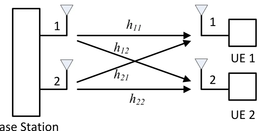
Base Station
UE
1
2
1
2
h
11
h
12
h
22
h
21
Base Station
UE 1
h
11
h
12
h
22
h
21
UE 2
1
2
1
[image:32.595.60.486.88.307.2]2
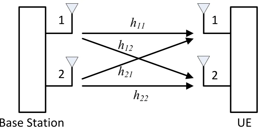
Figure 2.2: Single-UserMIMO transmission.
not subject to inter-cell interference, wherehtx,rxare the channel coefficients fromTx
antenna tx toRx antennarx which make up the channel matrixHk,O.
Commonly in SU-MIMO transmissions, three main methods are discussed:
transmit diversity, spatial multiplexing and beamforming, which are distinguished
by their different performance objectives. Transmit diversity operates by
transmitting the same signal over multiple antennas each coded differently using either space-time block codes (also known as Alamouti codes [10]) or their adapted
form space-frequency block codes. This has the effect of increasing the robustness of
the channel to error. Spatial multiplexing is the transmission of multiple data
streams over different spatial layers in such a way that they can be separated at the
receiver. This has the effect of increasing the capacity of the channel by the order of
the number of spatial layers used, which has a maximum of min(Nt, Nr,k). Finally, beamforming applies complex weights to transmissions on different antennas in
such a way as to combine constructively in the desired direction and destructively
in directions which would cause interference to other users. This has the effect of increasing the desired signal gain, while at the same time decreasing the level of
interference created. For each of these open- and closed- loop flavours exist,
corresponding to those in which channel knowledge at the transmitter (other than
for Modulation and Coding Scheme (MCS) selection) is not, and is, required,
Ch 5].
Of the SU-MIMO methods there is no one-size-fits-all best solution for all
wireless scenarios, hence in the standards a range of different multi-antenna
transmission modes are often defined. Famously, in trying to identify the optimal
way to use of multiple antennas, Zheng and Tse [12] quantified the tradeoff region
between link robustness provided by diversity and additional throughput provided by spatial multiplexing. However, in general the choice of transmission mode
depends on a number of factors including: Signal to Interference and Noise
Ratio (SINR),UE speed, channel correlation and traffic type.
Broadly speaking, in SU-MIMO, open-loop techniques should be used in high
velocity scenarios in which channel feedback is less reliable; diversity techniques
should be used in scenarios where high channel reliability is required, such as
control channels; spatial multiplexing should be used in cases where there is high
SINR and low correlation between the channels of different antennas; and
beamforming should be used in cases where the channels are highly correlated,
where increased SINR is required (e.g. on the cell edge) or where control is needed
over the emitted interference.
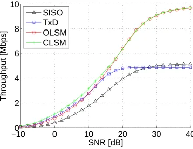
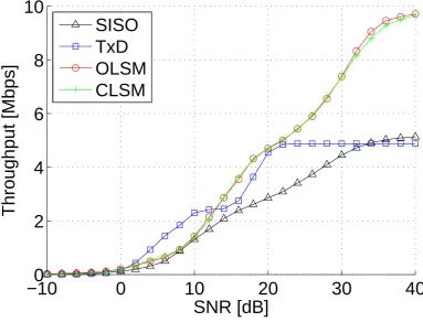
To demonstrate these points, Figures 2.3 and 2.4 compare the throughputs of
four LTE Transmission Modes (TMs) in low and high speed scenarios, respectively,
with varying Signal to Noise Ratio (SNR). These TMs are single antenna transmissions (SISO), Transmit Diversity (TxD), Open-Loop Spatial Multiplexing
(OLSM), and Closed-Loop Spatial Multiplexing (CLSM). These graphs were
generated using the Vienna Link Level (LL) downlink simulator [8] for a single eNB
and single UE with 2 Hybrid Automatic Repeat reQuest (H-ARQ) retransmissions,
a channel feedback delay of 5ms, and using the Typical Urban (TU) channel model [13] with low correlation between transmit antennas. As can be seen, the
multi-antenna techniques show superior performance to SISO transmissions in all
cases except for the TxD high SNR case, for which the losses in throughput from
feedback overhead exceed the gains from channel reliability. We see that at low speed (Fig. 2.3) the Closed-Loop transmissions provide higher throughput than the
other TMs for all SNRs, while at high speeds (Fig. 2.4) the Open-Loop
transmissions perform best with TxD showing best performance at low SNR and
OLSM at high SNR. The humps in this graph result from the use of H-ARQ,
−10
0
0
10
20
30
40
2
4
6
8
10
SNR [dB]
Throughput [Mbps]
[image:34.595.72.452.106.399.2]SISO
TxD
OLSM
CLSM
Figure 2.3: Comparison ofSU-MIMOtransmissions modes atUEspeed of 3kmph.
keeping the same modulation scheme. Hence, for increasing SNR, the humps
correspond to 4QAM, 16QAM and 64QAM, respectively.
In this thesis we focus on low mobility scenarios in which the correlation
between antennas is high (corresponding to close antenna spacings, low levels of
scattering, and/or strong Line-Of-Sight (LOS) components). For this reason, going
forward, use of the term SU-MIMO will mainly refer to beamforming operation,
also known as Closed-Loop Spatial Multiplexing (CLSM) on a single spatial layer in
LTE terminology, owing to the fact that in LTE this transmission mode operates in
the same way asCLSM, with the exception that only a single spatial layer is used.
In LTE CLSM on a single spatial layer the signal model can be expressed as follows
yk = Hk,Owkxk
| {z }
Desired Signal
+
NeN B−1 X
l=1
alHk,ldl
| {z }
Inter-Cell interference
+nW,k
| {z }
Noise
−10
0
0
10
20
30
40
2
4
6
8
10
SNR [dB]
Throughput [Mbps]
[image:35.595.121.505.108.400.2]SISO
TxD
OLSM
CLSM
Figure 2.4: Comparison ofSU-MIMOtransmissions modes atUE speed of 120kmph.
where the transmitted signal (dk in Eqn. (2.1)) consists of the transmitted symbol
xk with unitary precoding wk applied. The unitary precoding is selected from a
predefined codebook specific to the number of Tx antennas used. Figure 2.5 shows
the corresponding beam patterns for each of the entries in the LTE Rel.8 precoding codebook [14, Table 6.3.4.2.3-2] when applied to a Uniform Linear Array (ULA) of
dipole antennas with a half-wavelength inter-antenna spacing. As can be seen these
beam patterns generally have multiple strong lobes and multiple zeros in order to
allow interference restriction in multiple directions at once. The precoders in each
subfigure are all mutually orthogonal.
SU-MIMO Channel Feedback
TheLTE standards specify three types of Channel State Information (CSI) feedback
for use in the scheduling of UEs and adaptive modulation and coding. These are
−30 −20 −10 0 30 −150 60 −120 90 −90 120 −60 150 −30 180 0
PMI = 0 PMI = 1 PMI = 2 PMI = 3
(a) −30 −20 −10 0 30 −150 60 −120 90 −90 120 −60 150 −30 180 0
PMI = 4 PMI = 5 PMI = 6 PMI = 7
(b) −30 −20 −10 0 30 −150 60 −120 90 −90 120 −60 150 −30 180 0
PMI = 8 PMI = 9 PMI = 10 PMI = 11
(c) −30 −20 −10 0 30 −150 60 −120 90 −90 120 −60 150 −30 180 0
PMI = 12 PMI = 13 PMI = 14 PMI = 15
[image:36.595.77.470.92.425.2](d)
Figure 2.5: LTERelease 8 single-layer codebook beams for 4Txantenna uniform linear array.
Indicator (RI) [15]. TheCQI is a form ofSINR, quantised into one of 16 values, the
PMI recommends a linear precoding matrix from a predefined codebook, and the RI
indicates the rank (number of parallel transmission streams) to use. With regard to
the RI, going forward in this work, for both SU-MIMO and MU-MIMO operation, only Rank-1 transmissions for each UE will be considered.
TheCQIquantisation process proceeds as follows: for each of the 16 possibleCQI
values there is a corresponding MCS; the CQI is selected as the highest order MCS
which is expected to achieve a BLock Error Rate (BLER) no greater than 10% at the
UE’s SINR [16].
In LTE Rel.8 systems, recommended precoders are selected from a predefined
codebook C = {U0, . . . ,U2Nt−1} of Nt×NL unit-norm matrices, and the index of
the selected codeword in the codebook is called the PMI. Essentially this
regarding directionality of the strongest channel components (or the strongest
channel component for single-layer). The codebooks are defined in [14, Section
6.3.4]. PMI selection is based on the UEchannel matrix although the metric used in the selection varies between implementations. For example, the metric may target
the maximisation of the effective channel gain Ib(Ui) = det(UikHHHk,O,bHk,O,bUik)
(or equivalently Ib(Ui) = |Hk,O,buik|2 for single-layer [17]), where Ib(Ui) is the
metric computed for Resource Block (RB)(/subband) b ∈ {1, . . . , B} and B is the number ofRBs in the system bandwidth.
BothCQIandPMIfeedback can be specified as eitherwideband orsubband, while
for theRIonly wideband feedback is allowed. Put simply, widebandCSIcorresponds
to the best CSI, on average, if applied to the entire considered bandwidth, while
subband CSI is separately specified for each subbandRB.
WidebandCQIis computed by theUEby averaging theSINRs over allRBs using
Mutual Information EffectiveSINR Mapping (MIESM) (or a similar Effective SINR
Mapping (ESM) technique, as will be discussed in Section 3.1.2) before quantising
the resulting effective SINR into one of the 16 possible values.
The wideband PMI is selected as the PMI, which, when applied to the entire considered bandwidth, achieves the highest sum metric. In other words [18]
UPMI= argmax
Ui∈C
B
X
b=1
Ib(Ui). (2.3)
In LTE-A Rel.10 systems for 4 Tx antennas or less this is performed exactly the
same asLTE Rel.8, using the exact same codebook. For more than 4 Txantennas a new dual codebook is defined in whichboth wideband and subbandPMIs are selected
and fed back. In our investigations later in this work 4 Tx antennas will be used,
meaning that theLTE Rel.8 codebook is utilised.
The feedback specification methods discussed in this subsubsection apply to both
SU-MIMOand MU-MIMO transmissions.
2.1.2
Multi-User
MIMO
(
MU-MIMO
)
MU-MIMOis a spatial multiplexing technique in which multiple transmit antennas at
Base Station
UE
1
2
1
2
h
11
h
12
h
22
h
21
Base Station
UE 1
h
11
h
12
h
22
h
21
UE 2
1
2
1
[image:38.595.71.486.90.301.2]2
Figure 2.6: Multi-UserMIMOtransmission.
resource as shown in figure 2.6; this is achieved by transmitting to each UE on a
different spatial layer. Essentially this consists of applying precoding weights to direct
orthogonal beams at each served UE; in other words, performing beamforming with
multiple UEs at once in such a way that the interference between co-scheduled UEs
is minimised. Due toMU-MIMO’s ability to provide large spatial multiplexing gains
without requiring additional antennas on the UE, and its ability to overcome rank deficiency problems (which often limit single point-to-point spatial multiplexing),
MU-MIMOcapabilities have been highly emphasised in recent3GPPstandardisation
and in research projects such as FP7 Spectrum Aggregation and MU-MIMO:
ReAl-world Impact (SAMURAI) [19].
In a downlink scenario where a base station with Nt transmit antennas transmits
to K UEs, each with Nr,k receive antennas, the capacity of the channel scales with
min(Nt,PKk=1Nr,k). There are, however, some additional losses in the SINR, firstly,
due to the splitting of the transmit power across the co-scheduledUEs’ transmissions,
secondly due to any orthogonalisation operations (e.g. Zero-Forcing Beam Forming
(ZFBF)) in the precoding of transmissions to UEs with non-orthogonal quantised
channels, and thirdly, due to any residual Multi-User Interference (MUI) between
the UEs.
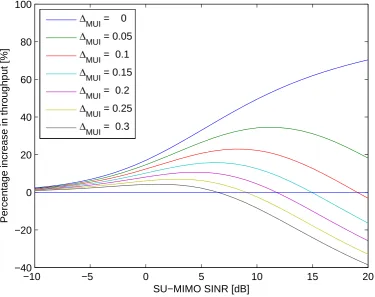
−10 −5 0 5 10 15 20 −40
−20 0 20 40 60 80 100
SU−MIMO SINR [dB]
Percentage increase in throughput [%]
∆MUI = 0
∆MUI = 0.05
∆MUI = 0.1
∆MUI = 0.15
∆MUI = 0.2
∆MUI = 0.25
[image:39.595.129.505.111.408.2]∆MUI = 0.3
Figure 2.7: Percentage throughput gain from usingMU-MIMOoverSU-MIMO.
to orthogonal (semi-orthogonal) quantised channel vectors (as specified by the PMI)
should be co-scheduled for MU-MIMO transmissions. Any residual MUI, which
primarily results from channel quantisation errors, should then be suppressed by the
receiver.
As an illustration of what MU-MIMO gains are possible, in Figure 2.7 we plot
the percentage throughput increases of MU-MIMO, with two co-scheduled UEs,
over Single-User MIMO beamforming on a single spatial stream (SU-MIMO), for
different levels of residual MUI after suppression, represented by the factor ∆M U I.
In this figure both UEs served simultaneously using MU-MIMO have equal SINRs and interference suppression capabilities, and their quantised channels are
orthogonal. ∆M U I ranges from 0 to 1, with higher ∆M U I representing higher
residual MUI (poor MUI suppression) and ∆M U I = 0 representing no residual MUI
(full MUI suppression). It must also be stated that due to CQI feedback
PMI
UE1
PMI
UE2
0 1 2 3 4 5 6 7 8 9 10 11 12 13 14 15
0
1
2
3
4
5
6
7
8
9
10
11
12
13
14
15
0
0.2
0.4
0.6
0.8
1
Figure 2.8: Correlations betweenLTERel.8 codebook 4Txsingle-layer precoding vectors.
gains at very low SINR are lost. As a result, a UE can benefit from MU-MIMO
transmissions if, firstly, its SINR is sufficiently high (greater than roughly 1.5dB), and secondly, there is another UE with a precoding matrix semi-orthogonal to its,
with which to pair.
Figure 2.7 was generated by computing 2-layer MU-MIMO SINRs for the given
range of single-layer SU-MIMO SINRs using Eqn.(3.6), which is obtained from [20].
Shannon rates are computed for theseSINRs and, in the case ofMU-MIMO, summed
over the two co-scheduled UEs.
As mentioned, in LTE and LTE-A systems, the orthogonality of co-scheduled
UEs is assessed based on their fed back PMI which indicates the directionality of the channel between the base station and the UE in quantised form. To illustrate the
orthogonality between different LTE Rel.8 codebook precoders, Figure 2.8 displays
the correlation of each possible 2 UE precoder combination in the 4 Tx antenna
case. If the correlation is zero (shown in dark blue) the codewords are orthogonal,
case, each codeword is orthogonal to at least 3 other codewords and that mutually
orthogonal codewords tend to be indexed in blocks of 4.
MU-MIMO Signal Model
ForMU-MIMO with nM U UEs co-scheduled, each transmitted to on a single spatial
layer (rank-1), the received signal of UE k, co-scheduled for MU-MIMO with UEs
j ∈ {1, . . . , nM U −1} , is given by
yk = Hk,Owkxk
| {z }
Desired Signal
+
nM U−1 X
j=1
Hk,Owjxj
| {z }
Multi-User Interference
+
NeN B−1 X
l=1
alHk,lWlxl
| {z }
Inter-Cell interference
+nW,k (2.4)
where yk represents the Nr×1 received signal vector, Hk,O represents the Nr×Nt
channel matrix within the original serving cell, wk represents the Nt ×1 applied
unitary precoding and xk represents the transmitted symbol, of UE k. Hk,Owjxj
represents the interference from co-scheduled UE j, while Hk,lWlxl represents the
interference from neighbouring celll and finally nW,k represent complex AWGNthe
elements of which have zero mean and varianceσ2. It should be noted that the value Hk,O in this equation includes the transmit power to each of the co-scheduled UEs,
which is n1
M U of the power it would have if they were scheduled forSU-MIMO alone. As indicated by al, if a neighbouringeNB is not active it does not produce inter-cell
interference. It is assumed that all serving cells are active, hence we omit the aO
which would otherwise precede Hk,O.
After a 1×Nr receive filter gk is applied we get the received symbol zk of user k
as
zk=gkyk. (2.5)
The post-reception SINR of UE k on a given subcarrier can be represented as
γk =
|gkHk,Owk|2
|gkPnM U
−1
j=1 Hk,Owj|2+|gk
PNeN B−1
l=1 alHk,lWl|2+σ2I||gk||2
MU-MIMO Transmission Strategies
MU-MIMO tranmissions can be performed in a number of different ways. Dirty
Paper Coding (DPC) [21] is a non-linear scheme which provides an upper bound on
MU-MIMO performance but is highly complex and requires full knowledge of the interference signal when decoding, making it not practical in reality. Instead this is
often used as a capacity upper bound for MU-MIMO channels. Zero-Forcing Beam
Forming (ZFBF) [22] is a linear precoding technique in which UEs are each served
on a single spatial layer and orthogonal precoders are selected for each UE in an
attempt to nullifyMUI. Block Diagonalisation (BD) [23] is another linear precoding
technique, this time with UEs each served on multiple spatial layers. This method
operates by nullifying interference between different UEs, although not nullifying
the interference between layers sent to the same UE. In this way a reduction in the
power losses required to enforce orthogonality can be achieved as interference between layers sent to a single UE can be successfully removed at the UE receiver.
Zero-Forcing (ZF) DPC [22] combines Zero-Forcing Beam Forming (ZFBF) and
Dirty Paper Coding (DPC) to achieve near optimal performance with much reduced
complexity (compared to DPC). This method however requires non-causal channel
knowledge and so cannot be used in real systems. Successive ZF DPC [24] is similar
toBD although for the ZF DPC case.
In LTE Rel.8 a UE can only be transmitted to on a single spatial layer and
only transmission to orthogonal UE pairs can be performed, meaning that none of
these techniques could yet be used. With the introduction of non-codebook based
precoding (enabled by the DM-RS) in LTE-A Rel.10, however, support for ZF and
BD was enabled. However, due to the presence of quantisation errors in the CSI
feedback, use of MU-MIMO often requires interference suppression at the receive
side, which requires multipleRx antennas [25]. WhenBDis used the combination of
UE antenna requirements for multiple spatial streams and interference suppression
results in the number of UE Rx antennas needed being quite high. For this reason
we focus on Zero-Forcing Beam Forming for MU-MIMO operation in this thesis,
implementation of which is discussed later in Section3.2.3, also the equations in the
0
20
40
60
80
100
0
0.5
1
1.5
2
2.5
3
3.5
x 10
5
Number of Users (K)
Complexity (FLOPs)
Greedy
SUS
Genetic
Brute
Figure 2.9: ZFBF2×1 computational complexity comparison of MU-MIMOschedulers.
MU-MIMO Scheduling
User scheduling is the most common method used to take advantage of multi-user
diversity. However, in MU-MIMO systems, user scheduling becomes a lot more
complex than inSU-MIMO systems. This is because the system performance is not
just a function of which UE is selected, but also of which UEs it is paired with; for
example, while in SU-MIMO taking a brute force approach would require
computing the objective function K times (where K is the number of UEs in the cell), trying all possibleMU-MIMO UE combinations to find the optimal set ofnM U
UEs requires PNM U
nM U=1
K nM U
objective function computations, where nM U is the
number of UEs co-scheduled for MU-MIMO with a maximum of NM U. As a result
greedy heuristics are commonly used.
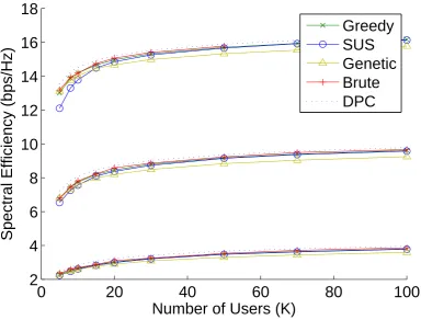
In figures 2.9 and 2.10 we compare the complexity and performance of a number
of different scheduling algorithms for 2 × 1 ZFBF MU-MIMO. The algorithms
0
20
40
60
80
100
2
4
6
8
10
12
14
16
18
Number of Users (K)
Spectral Efficiency (bps/Hz)
[image:44.595.75.460.106.398.2]Greedy
SUS
Genetic
Brute
DPC
Figure 2.10: ZFBF2×1 spectral efficiency comparison ofMU-MIMOscheduling algorithms. From bottom to top the three bands of curves correspond toSNRs of 0dB, 10dB and 20dB, respectively
successively selects UEs based on their expected rates (Greedy); the
Semi-orthogonal User Selection (SUS) algorithm in [27] which successively selects
UEs based on their channel gain, provided that their fed back precoding vector is
semi-orthogonal to those of the already scheduled UEs (SUS); the heuristic genetic
algorithm proposed in [28] (Genetic); and the brute force approach. For comparison
Figure2.10 also includes the DPC performance upper bound.
These figures were generated using Matlab-based code made available online at
[29] as part of the publication [30] to which we added the investigated scheduling
algorithms. Flop counting for complexity comparison was computed using the
Lightspeed Matlab toolbox [31]. We performed these simulations at link level
assuming perfect channel knowledge at the transmitter, with the maximum number
of co-scheduled UEs NM U=Nt=2, and for a range of SNRvalues as shown in Figure
2.10 [32].
would be impractical in real systems. On the other hand, theSUS algorithm, which
we use primarily in the following chapters, provides an extremely low complexity
solution which also achieves close to optimal performance for high numbers of UEs, and while the spectral efficiency is reduced when the number of UEs per cell is low,
overall this algorithm achieves a good tradeoff between complexity and performance1.
2.1.3
Coordinated Multi-Point (
CoMP
)
In this thesis our main focus is on the gains of downlink multi-antenna techniques
specifically focussing on small cell network scenarios with coordination. This focus
is shared with the more generalised group of techniques known as Coordinated
Multi-Point (CoMP). From a theoretical perspective the potential gains of CoMP
have been known for a considerable amount of time [33]; however, the costs involved in implementing the required coordination have, until recently, outweighed the
benefits. The recent uptake of new network architectures which centralise the
processing of multipleeNBs such as Cloud Radio Access Network (C-RAN) [34] and
liquid radio/baseband pooling [35] have led to cost effective solutions which greatly
simplify and accelerate coordination between neighbouring small cells. Amplifying
this, the emphasis of the 3GPP on supporting CoMP functionalities in LTE-A
systems (first discussed for Release 9 [36] with significant steps made in Release 11
[37]) has meant that this is a hot topic at the moment which is generating a lot of
interest from the research community [38]. Further emphasis on this sort of investigation has been encouraged by discussions such as [39], which asks questions
such as ”Is the PHY Layer Dead?” provoking a shift in telecommunications research
from a backdrop of incremental link level improvements toward new network
approaches with potentially high undiscovered gains.
The idea behind downlink CoMP is that UEs on the cell edge can often receive
transmissions from multiple base stations at once; if these transmissions are
coordinated then the performance of these UEs can be considerably increased. Very
good resources on the CoMP background and literature can be found in [38,40, 41],
as well as the 3GPP document onCoMP itself [37].
CoMP operates in three main ways: Coordinated Scheduling/Coordinated
Beamforming, Dynamic Cell(/Point) Selection, and Joint Transmission. These
Coordinated Scheduling/ Coordinated Beamforming
(a)
Dynamic Cell Selection OR
(b)
Joint Transmission
(c)
Figure 2.11: CoMPtransmission Types. (a) Coordinated Scheduling/Coordinated Beamforming, (b) Dynamic Cell Selection, (c) Joint Transmission.
transmission types are depicted in Figure 2.11. In this subsection we focus on
providing background on these three CoMP types, while the relationship between
these and our work will be discussed more precisely in Chapters 4 and 5.
Coordinated Scheduling/Coordinated Beamforming
In Coordinated Scheduling/Coordinated Beamforming (CS/CB) transmissions to each UE originate from a single serving base station(/transmission point) and the
scheduling processes of the set/cluster of cooperating eNBs (CoMP set) are
coordinated. As shown in Figure 2.11a, CS/CB operates by scheduling UEs such
that the intercell interference (marked in dashed lines) from the beams of the
scheduled UEs toward UEs operating within the same time/frequency resource in
adjacent cells is minimised. This is mainly done in two ways, which are referred to
in [40] as Coordinated Beam-Switching (CBS-CoMP) and Coordinated
Scheduling (CS-CoMP).
In CBS-CoMP base stations specify certain resources in which different beams
can be used (beam-to-resource assignment). This can be done in a time-domain
manner in which beams are cycled between according to a pattern specified through
coordination [42, 43], or in the frequency domain in which groups of subbands are
corresponding beam can be scheduled. CBS-CoMP provides effective interference
reductions at a low coordination signalling cost; however, these distributed solutions
are only suitable in cases where the number of UEs per cell is large, unlike the scenarios we consider.
In CS-CoMP methods a different approach is applied in which cell-edge UEs
inform their serving eNB of the set of either their worst-interfering (or
least-interfering) beams from neighbouring cells. This information is then fed to the neighbouring cells which either avoid (or steer toward) usage of those beams in the
scheduling decisions [46], [38, Sec 5.3 and references therein]. These methods are
largely distributed and require inter-cell feedback exchange in the form of beam
indexes (e.g. PMIs for the LTE Rel.8 predefined codebook of beams) and the
corresponding channel quality improvement (CQI improvement for LTE).
As specified in [37, Sec 5.1.3] CS/CB can also be performed in tandem with
Semi-Static Point Selection (SSPS) in which transmissions to a UE originate from
a single transmission point(/eNB) which can change semi-statically (on the order of
seconds). SSPS as a term appears to be as-of-yet relatively unused in the research
literature, although is very closely related to its more dynamic counterpart, DCS,
discussed in the following.
Dynamic Cell Selection
Dynamic Cell(/Point) Selection (DCS) is a form of CoMP Joint Processing (JP),
meaning that transmit data must be present at all eNBs within the cooperating
CoMP set. Despite this, transmissions to the served UE originate from a single
transmission point, as shown in Figure2.11b; although the transmission point can be dynamically switched from one subframe (1ms) to the next. DCS is often performed in along with muting [47] in which the transmissions of cooperating eNBs, when
not transmitting to the dynamically switching cell-edgeUE on a given subband, are
halted temporarily (replaced with Almost Blank Subframes (ABSs)), meaning that
Joint Transmission
Joint Transmission (JT) is the simultaneous transmission of data from multiple