Abstract—This paper presents an analysis of the factors that
have significant influences on fiber fusion splicing loss of two different commercial single-mode fibers: SMF-28 and MP980. Crucial parameters such as fusion current and fusion time including particular conditions are studied and demonstrated in this study to obtain low-loss fusion splicing. Fusion currents in the range of 13.4 – 13.8 mA with step of 0.1 mA were used in experiments to find the optimal values of splicing loss. Depending on the fusion currents, the experimental results showed the appropriate fusion times for mentioned currents were 2.6, 2.5, 2.4, 2.1, and 1.8 s, respectively. These results indicate that, in order to achieve low-loss fusion splicing, the fusion current is inversely proportional to fusion time. Yet, high fusion current, causing high arc temperature, does not always yield fiber fusion splicing with low loss due to the deformation of fiber cores prior to the fusion completion. The proposed conditions can definitely be applied to the practical industrial sector subject to fusion splicer.
Index Terms— Single-mode fibers, Optical fiber splicing, Fusion splice loss
I. INTRODUCTION
INGLE-MODE OPTICAL FIBER is regularly used in high-speed telecommunication system as it achieves low dispersion, immunity of electromagnetic interference (EMI), great data security, a high quality of optical signal transmission, and so on. Fiber connecting is a very important process in optical network. A thermal connecting, such as fusion splicing, has been widely used for such a long time since it yields a lower loss than other methods [1], [2]. Even though higher loss could be obtained from the fusion splicing between two dissimilar fibers, such a loss can be reduced by splicing under appropriate conditions. Research for the proper because most of the optical networks can have many conditions are among of interest to the optical industries sections that requires dissimilar fiber splicing. Therefore, the loss from such a splicing potentially becomes one of the most severe problems that limited the quality of
Manuscript received Dec 08, 2015; revised January 01, 2016
P. Khamdee is with Department of Electronic and Telecommunication Engineering, Faculty of Engineering. King’s Mongkut’s University of Technology Thonburi, Bangkok, 10140 THAILAND (phone: 6682-483-3248; e-mail: [email protected]).
A. Bhatranand is with Department of Electronic and Telecommunication Engineering, Faculty of Engineering. King’s Mongkut’s University of Technology Thonburi, Bangkok, 10140 THAILAND (e-mail: [email protected]).
Y. Jiraraksopakun is with Department of Electronic and Telecommunication Engineering, Faculty of Engineering. King’s Mongkut’s University of Technology Thonburi, Bangkok, 10140
the optical devices or system. To analyze the loss, mode-field matching is considered as the main cause of the fusion splicing loss of two dissimilar fibers. Splicing loss approximated by the theoretical estimation in [3]-[5] shows that the most important parameters are fusion time and fusion current. Other mechanical misalignments such as axial misalignment and angular misalignment also contribute the fiber splicing loss, but the amount is not considerable to one from mode filed mismatch in case of dissimilar fibers.
This paper presents the study of the aforementioned factors in the optical fiber splicing loss between SMF-28 and MP980 fibers. Theoretical background of splicing two dissimilar optical fibers (SMF-28 and MP980 fibers) is mentioned in section II, followed by the experiment setup and splicing loss measurement in section III. The experimental results and analysis discussion are stated in section IV and the conclusion is expressed in section V.
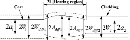
II. RELATED THEORY OF SPLICING TWO DISSIMILAR FIBERS Normally, splicing two similar optical fibers yields very low loss, but, unfortunately, this is not the case for two dissimilar fibers due to mismatched conditions such as core/cladding sizes, numerical apertures (NA), dopant concentrations, etc. The optical fusion splicing takes place around heating area with the length 2L as shown in Fig. 1. The junctions are thermally fusion by electric arc between two electrodes. This causes changes of diffusion coefficients in the transition area. The incompatibility of different fiber characteristics lead to high splicing loss. Thus, for each splicing, it is necessary to determine parameters properly and corresponding with the characteristics of two spliced fibers. One of the most crucial factors is fusion temperature or fusion current. Theoretically, the analysis has estimated the splicing loss as the function of fusion temperature, but, practically, arc current is used as the input parameter to the fusion splicer. The relationship between fusion temperature and fusion current is based on the stress relaxation [6]. Moreover, the fusion temperatures of typically over 2,100 °C with an improper fusion time mainly cause the deformation of fiber cores during the splice [7]. Other losses due to fiber axial and angular misalignments are very low compared to the core deformation.
The optimal parameters should minimize splicing loss and eliminate imperfect splicing. With improper fusion time and fusion current, the defected splice such as a bulge, waist, matchstick, and so on, might occur after the splice
Study on the Influential Factors in the Fusion
Splice Loss of SMF-28 and MP980 Fibers
Pennapa Khamdee,
Apichai Bhatranand, and Yuttapong Jiraraksopakun
Fig. 1. Schematic illustration of thermal diffusion expanded core area of fusion splicing between two fibers. [3]
III. EXPERIMENTAL SETUP AND SPLICING LOSS MEASUREMENT
This paper studies the fusion splicing between two popular single-mode optical fibers, SMF-28 and MP980 fibers, which are widely used in various optical communication devices and networks. SMF-28 is an ITU-T G.652 single-mode fiber and MP980 is a silica fiber doped with erbium atoms that respond to particular wavelengths, resulting in optical power amplification. For this reason, MP980 is used in optical devices, fiber lasers and erbium-doped fiber amplifiers (EDFA) as shown in Fig. 2.
WDM
TAP
TAP
Pump
EDFA
Signal
out
OI
Pump laser
Signal
in
OI
[image:2.595.62.277.62.129.2]OI: Optical isolator
Fig. 2. Schematic of erbium-doped fiber amplifier (EDFA) which is widely used in optical communication systems. [1]
In industry, device editing or reworking, as depicted in Fig. 3, is very important and this requires the fusion splice between these two famous dissimilar fibers in the optical devices. If MP980 is cleaved directly, it often causes great effect on the absorption and light amplification due to the changing of fiber length. Therefore, SMF-28 fiber is normally used to be cleaved (or reworked) instead of MP980 one.
A splicer (ERICSON: model FSU 995 FA) is used in the experimental setup to splice SMF-28 and MP980 fibers. This ERICSON splicer can handle simple single-mode to single-mode fiber splicing and complex splicing like erbium-doped fiber to single-mode fiber splicing [8]. The parameters set for fusion splicer are shown in Table I. Fusion current 2 and Fusion time 2 are carefully varied and observed due to their importance to fusion splicing loss as mentioned in section II.
SMF-28
MP980
WDM
Pump
Pump laser
Signal in
Rework
MP980
TABLEI
THE SPECIFICATIONS OF THE FUSION SPLICER
Parameters Values
Pre-Fusion time 0.2 s
Pre-Fusion current 10 mA
Gap 50
m
Overlap 10
m
Fusion time 1 0.2 s
Fusion current 1 10.5 mA
Fusion time 2 13.4-13.8 mA* Fusion current 2 1-5 sec*
Fusion time 3 1.8 s
Fusion current 3 12.5
m
Fusion time and current were set in the range of 13.4-13.8 mA and 1-5 s, respectively, corresponding to the actual values used in industry. Each experiment was extremely done under an industrial standard including the instruments and environments. All of the instruments were calibrated by the international laboratory and the environment was strictly controlled for working in the clean room.
The experimental setup is depicted in Fig. 4. The main source (a light source) is set at 1558.5 nm because this wavelength yields the highest optical output power after MP980 fiber is stimulated by the incident light [1]. The light then travels to the attenuator that is used to set an optical power reference. As dopant in EDF could affect the functional operation of instruments, an SMF-28 fiber spool is connected with MP980 at point 1 prior to splicing to MP980 fiber as shown in Fig. 4. Then, MP980 fiber is cleaved and put into the optical head to measure power out of its end and set it as a power reference. The preferable input power (reference) used in the industry and in this work is set at -30 dBm. Next, the fusion splicing of SMF-28 and MP980 is performed at point 2 and the optical output is measured by an optical multimeter. Finally, the splicing loss can be obtained by subtracting output power out of input power as illustrated in Fig. 5. The other losses in this system, such as connector loss, bending loss and instrument insertion losses, are cancelled out as they are already included in the reference and the measured output.
SMF-28 (SOURCE)
MP980
ATTENUATOR
MAIN SOURCE
SPOOL
(SOURCE)
SPLICER
OPTICAL
HEAD
OPTICAL
MULTIMETER
1
2
[image:2.595.51.292.320.378.2] [image:2.595.306.554.571.729.2]SMF-28
(Source)
1
MP980
2
SMF-28
Pin (dBm)
[image:3.595.313.554.55.272.2]Pout (dBm)
Fig. 5. Points where optical input and output powers are measured prior to the calculation for actual splicing loss of two dissimilar fibers at point 2.
IV. EXPERIMENTAL RESULTS AND DISCUSSIONS One vital factor for low-loss during our splicing experiments is the electrodes of a fusion splicer. The usability of the electrodes is limited by the number of splices and values of fusion current. Because of smudges after heating, the fusion possibly is not arced correctly. Then, the electrodes have to be adjusted and aligned prior to each splicing experiment. Therefore, splicing conditions of each experiment are slightly different from each other. To preserve the electrode conditions, three steps to find the optimal splicing condition is designed for each experiment. The fusion currents are 13.4 – 13.8 mA with a step of 0.1 mA and the Fusion times are 1 – 5 sec. Experiments have been conducted more than 1,300 splices to analyze the condition of SMF-28 and MP980 fusion splicing.
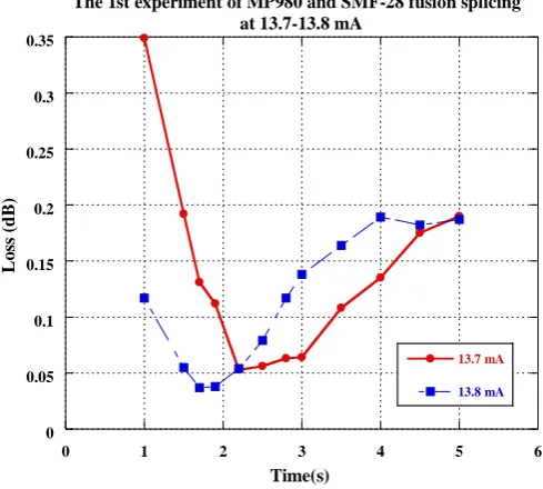
A. The 1st step of SMF-28 and MP980 fusion splicing This step performs splicing experiments in a wide range of the fusion time to quickly provide the rough idea of the fusion time where the lowest loss occurs as shown in Fig.6 and 7. For each fusion current, 12 steps of fusion times are conducted with 10 splicing trials. The 12 steps of the fusion times are 1.0, 1.5, 1.7, 1.9, 2.2, 2.5, 2.8, 3.0, 3.5, 4.0, 4.5 and 5 sec, respectively.
Our experimental results in Fig 6 and 7 has clearly demonstrated that the lowest splice loss lies in our predetermined range of fusion times. The results demonstrate the trend of higher splicing losses when the fusion time is longer than the range. This could be that the core of the fiber is deformed or melted as the temperature is too high. On the other hand, the shorten fusion time cannot splice two dissimilar fibers completely and results in higher splicing losses as well.
B. The 2nd step of SMF-28 and MP980 fusion splicing
tests
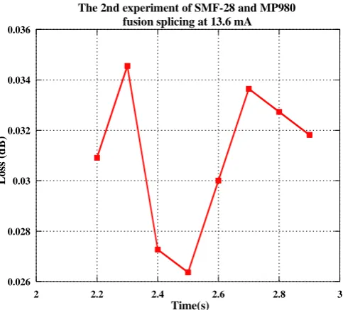
The finer ranges of fusion time based on the lowest splicing loss of each fusion current experiment in the 1st step were chosen to re-perform the splicing experiments. The finer fusion time ranges of each fusion current experiment are shown in Table II. Similarly to the previous experiments, 8 steps of finer fusion times were conducted with 11 splicing trials. The splicing results of each fusion current on the finer fusion times are shown in Fig. 8 – 12.
0 0.05 0.1 0.15 0.2 0.25
0 1 2 3 4 5 6
The 1st experiment of MP980 and SMF-28 fusion splicing at 13.4-13.6 mA
13.4 mA
13.5 mA
13.6 mA
L
os
s (
d
B
)
Time(s)
Fig. 6. The 1st step of experiment of SMF-28 and MP980 fusion splicing at
13.4 – 13.6 mA. This experiment has 12 steps of fusion time for each fusion current within 1 – 5 sec.
0 0.05 0.1 0.15 0.2 0.25 0.3 0.35
0 1 2 3 4 5 6
The 1st experiment of MP980 and SMF-28 fusion splicing at 13.7-13.8 mA
13.7 mA
13.8 mA
L
o
ss
(
d
B
)
[image:3.595.47.290.57.154.2]Time(s)
Fig. 7. The 1st step of experiment of SMF-28 and MP980 fusion splicing at
13.7 – 13.8 mA. This experiment has 12 steps of fusion time for each fusion current within 1 – 5 sec.
[image:3.595.309.554.335.555.2]TABLEII THE CONDITION OF THE 2ND
EXPERIMENT OF SMF-28 AND MP980 FUSION SPLICING
Fusion current (mA) Fusion time (sec)
13.4 2.2 - 2.9
13.5 2.2 - 2.9
13.6 2.2 - 2.9
13.7 2.0 - 2.7
13.8 1.5 - 2.2
0.035 0.04 0.045 0.05 0.055 0.06
2 2.2 2.4 2.6 2.8 3
The 2nd experiment of MP980 and SMF-28 fusion splicing at 13.4mA
L
o
ss
(
d
B
)
[image:4.595.312.554.53.271.2]Time(s)
Fig. 8. The 2nd step of experiment of SMF-28 and MP980 fusion splicing at
the fusion current of 13.4 mA. This experiment has 8 steps of fusion times within 2.2 – 2.9 sec.
0.025 0.03 0.035 0.04 0.045 0.05 0.055
2 2.2 2.4 2.6 2.8 3
The 2nd experiment of SMF-28 and MP980 fusion splicing at 13.5 mA
L
os
s (
d
B
)
[image:4.595.51.295.68.405.2]Time(s)
Fig. 9. The 2nd step of experiment of SMF-28 and MP980 fusion splicing at
the fusion current of 13.5 mA. This experiment has 8 steps of fusion times within 2.2 – 2.9 sec.
0.026 0.028 0.03 0.032 0.034 0.036
2 2.2 2.4 2.6 2.8 3
The 2nd experiment of SMF-28 and MP980 fusion splicing at 13.6 mA
L
os
s (
d
B
)
[image:4.595.311.552.340.557.2]Time(s)
Fig. 10. The 2nd step of experiment of SMF-28 and MP980 fusion splicing
at the fusion current of 13.6 mA. This experiment has 8 steps of fusion times within 2.2 – 2.9 sec.
0.035 0.04 0.045 0.05 0.055 0.06 0.065 0.07
1.8 2 2.2 2.4 2.6 2.8
The 2nd experiment of SMF-28 and MP980 fusion splicing at 13.7 mA
L
o
ss
(
d
B)
Time(s)
Fig. 11. The 2nd step of experiment of SMF-28 and MP980 fusion splicing
at the fusion current of 13.7 mA. This experiment has 8 steps of fusion times within 2.0 – 2.7 sec.
TABLEIII THE FINER CONDITIONS OF THE 2ND
EXPERIMENT OF SMF-28 AND MP980 FUSION SPLICING
Fusion current (mA) Fusion time (sec)
13.4 2.6 and 2.7
13.5 2.5 and 2.6
13.6 2.4 and 2.5
13.7 2.1 and 2.2
[image:4.595.54.297.476.693.2] [image:4.595.316.537.653.736.2]0.015 0.02 0.025 0.03 0.035 0.04 0.045 0.05 0.055
1.4 1.6 1.8 2 2.2 2.4
The 2nd experiment of SMF-28 and MP980 fusion splicing at 13.8 mA
L
o
ss
(
d
B)
[image:5.595.63.549.52.272.2]Time(s)
Fig. 12. The 2nd step of experiment of SMF-28 and MP980 fusion splicing
at 13.8 mA. This experiment has 8 steps of time for each Fusion current within 1.5 – 2.2 sec.
C. The 3rd step of SMF-28 and MP980 fusion splicing
tests
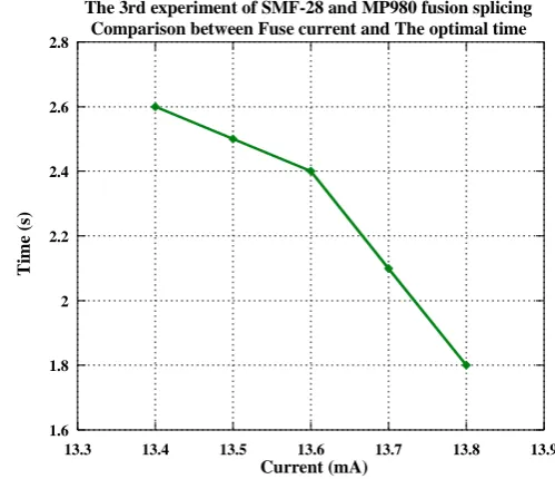
The range of fusion time based on the lowest splicing loss of each fusion current experiment in the 2nd step were narrowed down to two best values to re-do the experiments. The splices were conducted 32 times for each condition. The ultimate results for optimal fusion currents and fusion times are illustrated in Fig. 13.
It is clearly seen that, the higher the fusion current, the lower the fusion time. Therefore, to obtain the low-loss fusion splice, the relationship between the fusion current and the fusion time is inversely linear. Additionally, the experimental results in Fig. 13 correspond well to the theoretical ones depicted in [7].
V. CONCLUSION
This paper reports a study on the influential factors in the fusion splicing loss of SMF-28 and MP980 fibers. The fusion currents, varied from 13.4 mA to 13.5 mA with a step of 0.1 mA, corresponding with the fusion time of 2.6, 2.5, 2.4, 2.1, and 1.8 s, respectively, in order to obtain the minimum splicing loss. Experimental results showed that each fusion current has its own optimal time to achieve low-loss splicing. The relationship between splicing low-loss and fusion current or fusion time is not linear. Also, to achieve low splicing loss, the fusion time is inversely proportional to the fusion time. By increasing fusion current does not yield better splicing loss as expected since fiber core deformation occurs at high fusion temperature. Therefore, fusion current and fusion time are vital and sensitive parameters for fusion splice. The obtained values of fusion currents and times can be certainly used in the industry to obtain low-loss splicing.
1.6 1.8 2 2.2 2.4 2.6 2.8
13.3 13.4 13.5 13.6 13.7 13.8 13.9
The 3rd experiment of SMF-28 and MP980 fusion splicing Comparison between Fuse current and The optimal time
T
im
e
(s
)
Current (mA)
Fig. 13. The optimal fusion currents versus optimal fusion times for the fusion splicing of SMF-28 and MP980 fibers during the 3rd step.
ACKNOWLEDGEMENT
The authors would like to express deep gratitude to Fabrinet Company Limited for their generosity to provide all necessary equipment and facilities for this work.
REFERENCES
[1] Gerd Keiser, Optical fiber communications. 4th ed. Singapore:
McGraw-Hill, 2010.
[2] A. Selvarajan, S. Kara and T. Srinivas, Optical fiber communication
principles and system. New Delhi: McGraw-Hill, 2002, ch. 3.
[3] W.Inart and W.Asawamethapant., “The analysis of parameters related to fusion splicing loss of SMF-28 and MP980,” in 2012IEEE ECTI-CON Int. Conf., pp. 1-4.
[4] Marek Ratuszek, “Loss analysis of single mode telecommunication fiber thermally-diffused core areas,” Optica Applicata, vol. XXXVII, no. 3, pp.279-294, 2007.
[5] M. Ratuszek, Z. Zakrzewski and J. Majewski, “Reflectometric measurements of thermally expanded core area,” Bulletin of the polish academy of sciences technical sciences, vol. 58, no. 4, pp. 513-517, 2010.
[6] Y. Mohanna, “Electric arc temperature estimation of a fibre splicer,”
IEE Proc.-Optoelectron, vol. 142, no. 6, pp. 313-314, Dec. 1975.
[7] I. Hatakeyama and H. Tsuchiya, “Fusion splices for single-mode optical fibers,” IEEE journal of quantum electronics, vol. QE-14, no. 8, pp. 614-619, Aug. 1978.
[8] The FSU 995 FA single fiber fusion splicer manual, Ericsson Cables AB Inc., Sweden.
[image:5.595.302.552.55.270.2]Apichai Bhatranand received the B.E. degree in Electrical Engineering from Mahidol University, Thailand, in 1995. He received his M.E. and Ph.D. also in Electrical Engineering from Texas A&M University, USA, in 1998 and 2004, respectively. He has been a lecturer at department of Electronics and Telecom-munication Engineering, Faculty of Engineering, King Mongkut’s University of Technology Thonburi, Thailand since May 2004. His areas of interest are optical sensors, optical communications, and integrated optics.