On-Line Testability in a Transformation-Based
and Cost Function-Driven High-Level Synthesis Environment
Petros OIKONOMAKOS
Mark ZWOLINSKI
Electronic Systems Design Group, Department of Electronics and Computer Science
University of Southampton, Southampton SO17 1BJ, UK
{po00r,mz}@ecs.soton.ac.uk
Abstract
On-line testability is essential in designs with high reliability requirements. High-level synthesis reduces time-to-market and enables efficient design space exploration. In our work, we implement on-line testable designs in a high-level synthesis environment. We refer to our new technique (inversion testing) and exploit its features, in an attempt to reduce hardware penalties. Further, we enhance the design space by providing a metric for on-line testability.
1. Introduction
Many attempts (e.g. [2,4]) have been made to utilize components’ idle time* in synchronous synthesized
designs, in order to provide self-checking properties. When the idle time available is not enough, such
*
A component in a synchronous system is considered to be idle during a particular control step if it is not fed by useful data and does not produce useful results during that control step.
techniques turn to either time [4] or hardware [2] redundancy. Time redundancy refers to tolerating some performance degradation while introducing as little extra hardware as possible, while in hardware-redundancy based techniques some hardware overhead is accepted, in an attempt to meet strict performance requirements. In our Data path “Glue” logic Controller
Primary Inputs
Primary Outputs
Control Signals
[image:1.596.319.520.222.628.2]Next State Signals
Figure 1. Target architecture
transform and data selection
execution validity test
cost estimation transformation
valid?
perform transformation?
perform another transformation? yes
yes no
no no
yes
[image:1.596.63.283.423.608.2]end
approach, we include self-checking resource insertion in the synthesis and optimization phase of an existing high-level synthesis system. This way, on -line testable designs can be automatically produced (i.e. no modification of HDL code required), while the existing system properties and functionality guarantee that the choice between time or hardware redundancy is effectively up to the designer.
2. Existing synthesis system
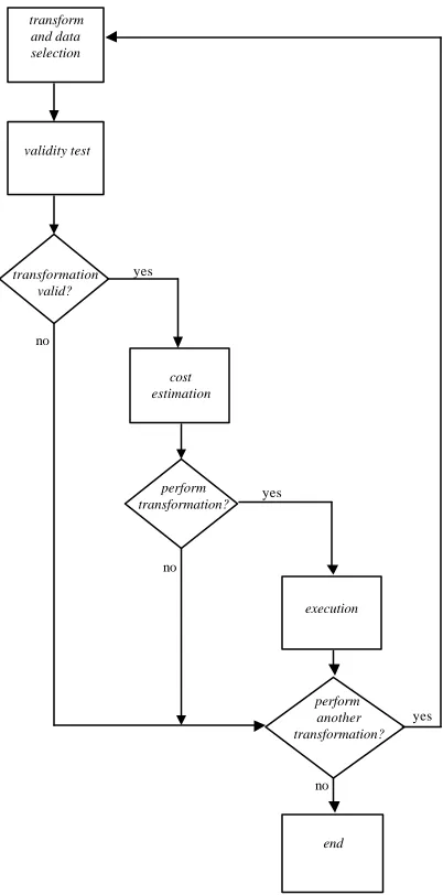
[image:2.596.312.533.289.403.2]We have been using the MOODS High-Level Synthesis Suite [3], developed in the University of Southampton. It is a cost-function driven, transformation-based system, and its resulting designs consist of a data path and a controller, joined together by glue logic, as depicted in figure 1.
When MOODS is first invoked, the behavioural HDL description is parsed, and an initial, naïve implementation of the design is formulated. Consequently, scheduling and allocation transforms are selected (from a set of available transforms), their validity is tested, their impact on the design parameters is evaluated (through a cost function which reflects designer requirements – chip area and delay are typical examples of such requirements), and some of them are applied, thus optimizing the design. The optimization loop of figure 2 illustrates these ideas and forms the nucleus of the optimization process. The overall optimization process consists of multiple repetitions of this loop, while the decisions regarding transforms to be considered and whether or not they will actually be applied are taken either by the designer interacting with the system, or fully automatically by an algorithm controlling the design process.
3. Proposed techniques
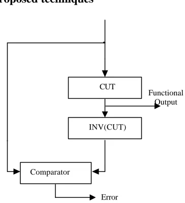
The well-known duplication testing scheme forms the basis of our self-checking technique. We also utilize the inversion testing scheme (figure 3), which we proposed in [1]. Experiments in [1] show that inversion supplement duplication, by providing an additional degree of freedom to the system towards minimizing hardware overheads associated with test insertion. In both the duplication and inversion cases, every effort is made to achieve maximum hardware utilization, by effectively applying algorithmic [2] (as opposed to physical) duplication / inversion, once more in order to provide as compact designs as possible. Algorithmic duplication (inversion) refers to duplicating (inverting) operations (rather than operators – hardware modules). Two simple data flow graphs to provide the motivation for the above ideas are sho wn in figure 4.
In figure 4a, three identical operations (additions) are scheduled over control steps 1 and 2 and assigned to
modules (adders) A1 and A2 as shown in the figure. Let us assume that after control step 3 control returns to control step 1 (as is the normal practice in data flow graphs). Note that both A1 and A2 are idle during control step 3, while A2 is also idle during control step 1. Straightforward physical duplication of adder modules would necessarily lead to 4 adders. However, we can utilize adders A1 and A2 in their idle control step 3 in order to algorithmically duplicate operations +3 and +1 respectively, while we can also utilize A2 during its idle control step 1 to duplicate operation +2. This way, we have introduced duplicates for all our normal addition operations without introducing any new adder modules at all.
[image:2.596.79.261.508.708.2]In figure 4b, addition +1 is assigned to adder A1 during control step 1, while an operation of the inverse type (subtraction –1) is assigned to subtractor S1 during control step 3. Since only one module of each kind is available, applying duplication testing would necessarily lead to physical duplication of both modules. Note, however, that both the adder and the subtractor are idle during control step 2. Assuming once more that after control step 3 control returns to 1, we can utilize A1 to invert -1 and S1 to invert +1 during control step 2. Thus, we can achieve algorithmic inversion of both operations, Figure 3. Inversion Testing
Comparator
Error CUT
INV(CUT)
Functional Output
1
2
3
+ 1
+ 3
* 1 + 2
A 1
M 1 A 2 A 1
(a) Suitable for algorithmic duplication
1
2
3
+ 1
* 2
- 1 * 1
A 1
S 1 M 2 M 1
(b) Suitable for algorithmic inversion
again without having to introduce any adder / subtractor module at all.
4. Incorporation within MOODS
As described in section 2, synthesis within MOODS relies on the following three elements :
- the set of available transforms - the cost function
- the applied algorithm
Therefore, the first step towards automation is defining appropriate transforms that insert on-line testing (duplication, inversion) schemes within the optimization process. For this purpose, we have supplemented the existing set of scheduling, allocation and binding transformations with three on-line testing related transformations. Namely, we have implemented two transformations to provide on -line testing resources (one for duplication and one for inversion) to operations, as well as a transformation to remove those resources. This way, on-line test resource insertion is dealt with within the
optimization process (and no modification of input HDL code is required).
Consequently, the existing cost function has to be supplemented with a metric for on-line testability, thereby leading to a three-dimensional des ign space (area, delay, on-line testability). Finally, existing algorithms can be modified to include these modifications, or testability oriented heuristics can be investigated.
5. Progress so far and results
Preliminary results presented in [1] justified the validity of our techniques and demonstrated the design space exploration process and the trade-offs associated with applying duplication, inversion or both techniques in benchmark designs. Ever since, we have been able to provide the system with the above mentioned transforms, which enables us to insert on -line testing resources by interacting with the MOODS graphic user interface. As already mentioned, this requires no input HDL modification, but still involves designer intervention.
Resource Usage Speed Parameters Testing Penalty Version Slices Tristate
Buffers
Cycles Maximum Frequency
Hardware Overhead (slices %)
Performance Degradation (cycles %)
Average Error Latency (cycles)
Original 137 400 7 50 MHz N/A N/A ∞
Duplicated 164 704 7 35 MHz 19.7 0 0
Inverted_1 156 720 7 4 MHz 13.9 0 0
Inverted_2 163 752 12 42 MHz 19.0 71.4 1.25
Table 1 : Tseng Benchmark synthesis results (Target Technology Xilinx Virtex XCV800 FPGA)
Resource Usage Speed Parameters Testing Penalty Version Slices Tristate
Buffers
Cycles Maximum Frequency
Hardware Overhead (slices %)
Performance Degradation (cycles %)
Average Error Latency (cycles)
Original 234 642 13 31 MHz N/A N/A ∞
Duplicated 344 1106 13 29 MHz 47.0 0 0
Inverted_1 328 1106 13 5 MHz 40.2 0 0
Inverted_2 404 1154 15 29 MHz 72.6 15.4 0.92 Table 2 : Diffeq Benchmark synthesis results (Target Technology Xilinx Virtex XCV800 FPGA)
Resource Usage Testing Penalty
Hardware Overhead Version Slices Tristate
Buffers
Cycles
slices % tristate buffers %
Performance Degradation (cycles %)
Original 470 2626 34 N/A N/A N/A
Duplicated 750 6548 36 59.6 149.4 5.9
[image:3.596.73.509.363.722.2]Inverted 762 6915 37 62.1 163.3 8.8
Therefore, we refer to it as a semi-automatic, interactive approach.
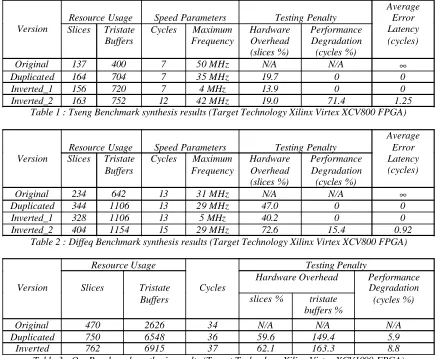
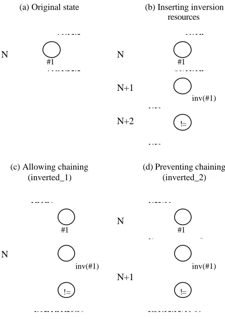
We have been experimenting with three High Level Synthesis Workshop benchmark designs, namely tseng (1991), diffeq (1992) and qrs (1995). Tseng is an example design with no physical significance, diffeq is a differential equation solver, while qrs is a medical electronics application consisting of more than 70 operations. Obtained results are summarized in tables 1-3. In all three tables, original versions are the untestable ones, duplicated versions have had the algorithmic duplication testing scheme applied to all their operations, while in inverted versions the inversion testing technique is preferred where applicable. Further, in tables 1 and 2 two different inverted versions are reported. The difference between them is illustrated in figure 4. Figure 4a shows a single control state (N) that forms part of a data flow graph, before any testing scheme is applied. In figure 4b, two additional control steps (N+1, N+2) have been introduced to accommodate the inverse and comparison operations. Let us assume that the clock period is high enough for the inverse and comparison operations to fit in a single control step. In figure 4c, we have let the system
chain normal and inverse operations within the same
control step, thus producing the chained inverted_1 version. Clearly, this requires an increase in clock period (therefore a decrease in clock frequency), in order for both operations to fit in the same control step, but results in no additional control step. In contrast, if we disable chaining (figure 4d), the normal operation and its inverse remain in separate control steps and therefore the clock period does not need to be lengthened; the price to pay is, of course, an extra control step (also shown in figure 4d). This non-chained version is referred in the tables as inverted_2. Note that such dilemmas do not apply to the duplication case, since an operation and its duplicate scheduled in the same control step, are executed in parallel (as opposed to serial execution in the inversion case), and therefore there is never a need to dramatically lengthen the clock period.
Coming back to the tables, we note that the chained inverted_1 versions are the smallest (therefore cheapest) self-checking versions in the first two cases. As expected though, they suffer from severe frequency degradation. In case this cannot be tolerated, the designer will have to settle for either of the other two. For the Tseng benchmark, they are of about the same size, and the choice is between a slightly higher frequency but a degradation in the number of clock cycles (inverted_2) or vice versa (duplicated). In the diffeq benchmark, the duplicated version is both smaller and faster than the inverted_2 one. In table 3, it can be seen that for the qrs benchmark, the duplicated version is once more both smaller and faster.
The above discussion demonstrates the process of exploring the design space until a realization that best suits the designer’s needs and requirements is met. Clearly, being able to explore the design space without having to change the behavioural description each time a new realization is to be tried, is a significant step forward, since it minimizes designer effort and greatly speeds the whole process up. Further, through the above discussion we have illustrated our statement that inversion provides an additional degree of freedom towards minimizing test insertion costs.
We are currently working towards quantifying on-line testability. As a first approach, we have been able to identify that such a metric should be a function of the following parametres :
- percentage of normal operations that have had testing schemes attached to them
- percentage of idle time availability per functional module - average (per operation) error latency*
As far as the algorithm to be used is concerned, we still rely on the (already implemented) simulated annealing [3] algorithm, slightly modified to favor our additional
* [image:4.596.58.281.383.699.2]
Error latency is defined as the number of clock cycles between the occurrence and the detection of a fault. Figure 5. Chained and non-chained invertion
#1 #1
inv(#1)
!=
(a) Original state (b) Inserting inversion
resources
(c) Allowing chaining (inverted_1)
(d) Preventing chaining (inverted_2)
N N
N+1
N+2
N
N
N+1
#1
inv(#1)
!=
#1
inv(#1)
transforms over the traditional ones, and followed by existing conventional (area, delay) specification-oriented heuristics [3].
Clearly, in the MOODS context, the combination of transforms, metric and algorithm leads to full automation. We are confident that full automation results will be available soon.
6. Conclusion
The contribution of this research work can be summarized in the following three points.
Test resources are inserted automatically at the behavioural level. No modification of HDL description is required. Thus, designs of substantial (industrial) sizes can easily be made on-line testable (for the first time).
The inversion testing technique provides additional flexibility towards minimizing overheads.
On-line testability emerges as an additional dimension in the design space. We expect this idea to be useful in other contexts as well.
7. References
[1] P. Oikonomakos, M. Zwolinski, “Using High-Level Synthesis to Implement On-Line Testability”, IEEE/IEE Real-Time Embedded Systems Workshop, London, UK, 2001. [2] A. Orailoglu, R. Karri, “Automatic Synthesis of Self-Recovering VLSI Systems”, IEEE Transactions on Computers, Vol. 45, No. 2, February 1996, p. 131-142.
[3] A.C. Williams, “A Behavioural VHDL synthesis system using data path optimisation”, PhD Thesis, University of Southampton, 1997.