http://www.scirp.org/journal/jbise ISSN Online: 1937-688X
ISSN Print: 1937-6871
The Effect of Traction Position in Cervical
Traction Therapy Based on Dynamic
Simulation Models
Lawrence K. F. Wong
1, Zhiwei Luo
1, Nobuyuki Kurusu
21Graduate School of System Informatics, Kobe University, Kobe, Japan 2Kobe Factory of Minato Medical Science Co., LTD., Kobe, Japan
Abstract
This study describes the development of a cervical traction therapy simulation model that evaluates two types of the traction positions, namely the sitting position and the inclined position. An anatomically correct human skeleton model and two mechanical traction device models were constructed in simu-lations using a physics engine. The anterior and posterior intervertebral sepa-rations were measured at both positions with a series of traction forces (60N to 200N) and traction angles (10˚ to 40˚). The result suggested that the sitting position caused the subject to lean forward and as a result led to excessive an-terior compression when traction angle is over 20 degrees. The inclined posi-tion creates greater intervertebral separaposi-tions on both the anterior and post-erior sides than the sitting position. This suggests that the inclined position may be more effective in increasing intervertebral separation than the sitting position.
Keywords
Cervical Traction Therapy, Spine, Traction Position, Dynamic Simulation
1. Introduction
Neck pain is a very common problem in the general population. In the “The Empowerment of People with Neck Pain: Introduction”, Haldeman et al. [1] states that “most people can expect to experience some degree of neck pain in their lifetime”. According to Judovich et al.[2], neck pain accounts for 15% of all soft tissue problems and 26% to 71% of the adult population experienced an ep-isode of neck pain or stiffness in their lifetime. In an extensive literature review “The Burden and Determinants of Neck Pain in the General Population” [3], it How to cite this paper: Wong, L.K.F., Luo,
Z.W. and Kurusu, N. (2017) The Effect of Traction Position in Cervical Traction The- rapy Based on Dynamic Simulation Mod-els. J. Biomedical Science and Engineering, 10, 243-256.
https://doi.org/10.4236/jbise.2017.105019
Received: February 9, 2017 Accepted: May 21, 2017 Published: May 24, 2017
Copyright © 2017 by authors and Scientific Research Publishing Inc. This work is licensed under the Creative Commons Attribution International License (CC BY 4.0).
http://creativecommons.org/licenses/by/4.0/
was suggested that about 30% - 50% of the general adult population experience neck pain that lasts for 12 months. There are many options that can help ease the pain on the neck. Cervical traction therapy, also known as non-surgical spal decompression therapy, is one of the possible treatment options frequently in-cluded in rehabilitation programs.
1.1. Cervical Traction Therapy
Cervical traction therapy refers to any medical procedure that applies force along the inferior-superior axis of the spine to extend the cervical spine verte-brae. Its purpose is often to straighten the back, to relieve pressure on the spine and to increase blood flow to the injured area. For decades, traction therapy has been widely employed in nonsurgical therapies and rehabilitation to treat chronic neck pain caused by herniated discs and other injuries at the cervical spine region.
Cervical traction therapy can be mainly divided into manual traction and mechanical traction. A manual therapy is performed by a trained physical the-rapist or chiropractor with the patient usually lies flat in bed. In a mechanical traction therapy, the patient’s head is attached to a head halter and is gently pulled by a motorized traction machine at a specific degree. Traction position varies in mechanical traction. In this case, the patient can sit upright on a chair at 90˚, referred to as the sitting position, or at an inclined angle, known as the inclined position.
Cervical traction therapy has been widely adopted in clinics and rehabilitation centers. Over the year, many studies have demonstrated its positive effects on cervical and lumbar spine-related pain [4] [5] [6]. However, some review studies [7] [8] [9] pointed out that further research is needed, since there is not enough conclusive evidence to fully support the contribution of the therapy. Therefore, it is important to conduct a qualitative study on the mechanics of the therapy.
1.2. Dynamic Simulation
In recent years, along with computer technology advancement, multi-body dy-namic simulation engines are now able to realistically simulate real world me-chanical systems based on the laws of physics. These advanced physics-based models helped researchers to generate animated simulation of physical events with high degree of precision and flexibility [10] [11]. Physics-based modelling is particularly popular among researchers as it allows the user to interact with the model in real-time with the virtual world and to adjust the various mechanical properties of the model to match the target test subjects. Several studies [11] [12] [13] have developed multi-body cervical spine to study the human head-neck response to impact loading.
1.3. Purpose of This Research
ve-rify the efficacy of cervical traction, it is necessary to first identify the various factors that cause intervertebral separations between the C2 and C7 vertebrae in a cervical traction therapy. While previous studies have examined how different traction angles and forces affect the efficacy [14], it is important to point out that traction position also plays an important role in the efficacy of cervical traction due to the mass distribution of the body. The two most common traction posi-tions are the sitting and supine posiposi-tions. Previous research studies [15] [16] have evaluated the two positions and concluded that supine position is more ef-fective in terms of the patient’s cardiovascular responses and the cervical inter-vertebral separations. In our research, we conducted a comparative study on the sitting position and the inclined position. In the inclined position, the patient is required to sit on a motorized rotatable chair at an inclined angle. While other research studies focused on the effects of individual patients, our simulation models can allow customizations of body dimension and weights to further ex-amine the effects of the therapy.
In our model, both the human skeleton and the traction equipment are placed together in a physics-based simulation environment, so that we can compare and analyze how different traction angles, forces and traction positions affect the distance of separation between each vertebra. The result will provide insight on the benefits and drawbacks of each traction factors and will serve as a reference for therapists to determine which setup is better under different circumstances. While many physical therapists and patients may not be familiar with the engi-neering concepts in a cervical traction therapy, a realistic simulation of the cer-vical vertebrae behavior during the therapy can act as a graphical tool to com-municate what actually happens. Furthermore, traction therapy equipment manufacturers can also benefit from this research, as they can use our model to help refine the design of their products.
2. Methods
2.1. Cervical Spine Model
The cervical spine component was created based on an anatomically correct human skeleton 3D model retrieved from BodyParts3D/Anatomography [17] and it consisted of 8 rigid parts: a human skull and 7 pieces of the cervical verte-brae. In order to minimize processing load in the simulation, all the bones in the skull were combined to create a simple rigid part to represent the skull. All the bones that made up the cranium and the facial area were combined into one ri-gid body. The cervical vertebrae (C1-C7) were modeled separately and each cer-vical vertebra was attached to the adjacent vertebrae by a spring-like joint with stiffness and damping settings that mimics the natural behavior of the cervical disc. The lateral flexion and axial rotation were prohibited in the model to sim-plify the simulation and reduce processing load. Only flexion and extension were allowed in the model.
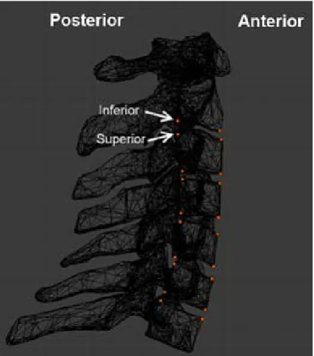
defining the reference points along the cervical spine, small sensors were created and attached to the C2 to C7 vertebrae. The sensors are weightless so they do not interference with the flexion and extension of the spine. They are attached to the C3, C4, C5, and C6 vertebrae in four positions, namely Anterior Superior, Ante-rior InfeAnte-rior, PosteAnte-rior SupeAnte-rior and PosteAnte-rior InfeAnte-rior. In C2, only the infeAnte-rior side had sensors attached and in C7, only the superior side had sensors attached. The positions of the sensors are shown in Figure 1. Once the sensors were at-tached to the designated positions of the vertebrae, they moved along with the vertebrae. By simply measuring the distance between sensors, the separation distance between each vertebra could be acquired.
2.2. Human Skeleton Model
[image:4.595.261.488.460.717.2]The human skeleton section of the model included the rest of the body below the cervical spine, and was modelled as separated rigid bodies. Similar to the cervical spine, all the 3D models used in this section were retrieved from BodyParts3D [17]. Each part was imported into 3D modelling software [18] for scaling and re-positioning with the traction equipment. The topmost part of the trunk was cut off at the first vertebra of the lumbar spine (T1) and this would serve as a support for the lowest part of the cervical spine (C7). The two arms were at-tached to the trunk by ball-socket joints that fixed each arm on to the trunk at a single point and allowed it to move freely in all directions. The legs were sepa-rated into upper legs and lower legs. The upper legs (thigh) were attached to the pelvis at the hip and the lower legs (shank) were attached to the upper legs at the knees. All the parts were connected with hinge joints that forced the attached parts to rotate around one axis.
The body segment mass data was configured based on the data from Zatsi-orsky et al. with adjustment made by DeLeva [19]. The human body model was 1.74 m tall and weighted 73 kg. The mass of each bone was calculated based on the percentage listed in the body segment parameter data and is shown in Table 1. The combined head and neck was estimated to be 5.07 kg. It is worth noting this value includes the brain, the cervical spine and all the tissues around the neck.
2.3. Traction Equipment Development
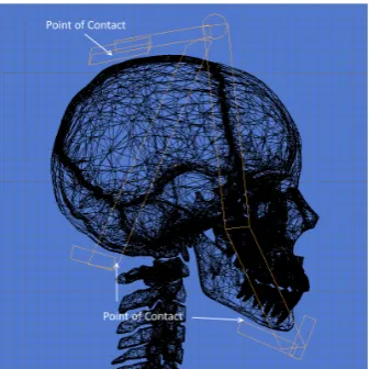
A typical set of traction equipment includes a head halter, a pelvic belt, a spreader bar, a rope and a weight. Depending on the design of the head halter, the direction of force varies. Thus, it is important to predefine the points of con-tact between the head and the halter so to identify the final acting force vector on the head. In the current model, the chin and the back of the head were se-lected as two contact points for the pulling force to apply on. The top part of the back of the head does not come in contact with the halter when traction is ap-plied during the therapy. It is only when there is no pulling force that the halter will rest on the head. Rendered images of the halter and the points of contact are illustrated in Figure 2.
[image:5.595.290.459.369.537.2]Figure 2. Head halter model.
Table 1.Body Segment Mass
Bone Names Mass (% of body weight)* Mass (kg)
Head + Neck 6.94 5.07
Upper + Mid Trunk 32.29 23.57
Lower Trunk (pelvis) 11.17 8.15
Upper Arms 2.71 × 2 1.98 × 2
Forearms + Hands 2.23 × 2 1.63 × 2
Thighs 14.16 × 2 10.34 × 2
Shanks + Feet 5.70 × 2 4.16 × 2
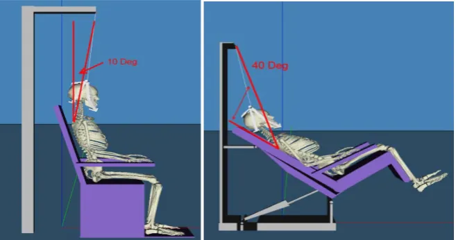
[image:5.595.208.540.587.730.2]We implemented two types of traction device and they represent the sitting position and the inclined position. In the sitting position, the subject sits up right on a chair with the head attached to a head halter. The traction device ap-plies a constant and continuous force to pull the halter upwards at an angle. The traction force can be set to between 60N to 200N and the traction angle can be set at 10˚/20˚/30˚/40˚. The sitting position was modelled based on the Minato Tractizer TC-30D. The halter is being pulled at 10˚ in Figure 3 in the sitting po-sition. In the inclined position, the subject sits on a motorized chair that can be rotated at any angle between 10˚ and 40˚. The pivot point of the head halter does not change position. The traction angle is controlled only by the rotation of the chair. The inclined position was modelled based on the Minato Tractizer TC-C1. Instead of pulling the subject upward/forward at an angle as in the sitting posi-tion, the inclined position rotates the base of the chair to form the traction angle. The name “inclined” describes the position of the rotated chair during the ther-apy, in which it looks like an incliner chair. This position aims to keep the sub-ject remain in the chair using gravity while at the same time reduce the size of the device. Figure 3 shows the halter being pulled at 40˚ in the inclined position. In both models, the traction angle’s vertex is at the center point of the subject’s first thoracic vertebra (T1). Both simulation models were developed in C++ in Microsoft Visual Studio using Vortex Dynamics 3.0 (CM Labs) [20].
3. Results
[image:6.595.210.539.537.710.2]Simulation runs were performed using combinations of traction angles, forces and positions. In each run, both the anterior and posterior intervertebral separa-tions between C2-C7 vertebrae were measured. Traction angle between 10˚ and 40˚ and traction force between 60N and 200N were tested. Both sitting and in-clined positions were tested under the same environment, i.e. all the material properties, stiffness and damping parameters of the mechanical joints were the same in both simulations. The measured separations represent the changes of separation before and after traction applied.
3.1. Intervertebral Separations vs. Time
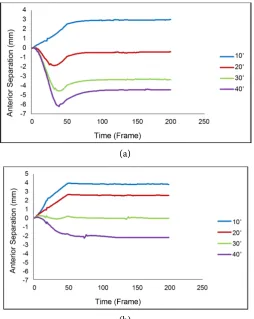
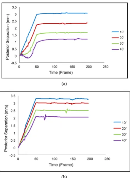
The changes of the anterior and posterior separations are shown in Figure 4 and Figure 5. Only the data from 160N is presented since the observed behaviors are similar with different traction forces. The measurement represents the overall combined disc space from C2 to C7. On the anterior side in Figure 4, negative separations occurred when traction angles increase. The negative dips were much more noticeable in the sitting position compared to the posterior case. Traction angle at 10˚ resulted in the largest separations while 40˚ traction angle resulted in compressed cervical spine. Similarly, the posterior side of the sitting position in Figure 5 also shows small dips at the beginning of the test at the 30˚ and 40˚ lines. The dips become more apparent as the traction angle increases. In the 40˚ case, negative separation was observed, indicating that the spine was be-ing compressed rather than extended. Negative separation was not seen in the inclined position. The largest posterior separation was achieved at 10˚ and the smallest at 40˚. The inclined position led to larger separations in all traction an- gles when compared to the sitting position. The stretched cervical spine in sit-ting and inclined positions at 10˚ and 40˚ are shown in Figure 6 and Figure 7.
[image:7.595.247.502.387.707.2]3.2. Individual Intervertebral Separations
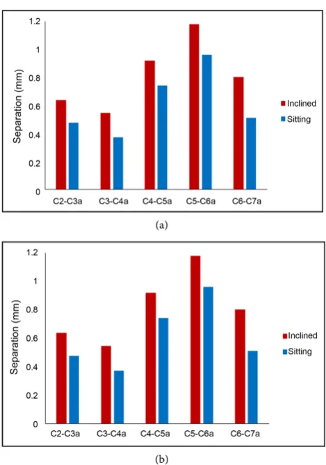
Figure 8 shows the segmental separations, from C2 to C7 on the anterior side.
(a)
(b)
(a)
(b)
Figure 5. Posterior Separations at 160 n in sitting (a) and inclined (b) positions.
[image:8.595.264.484.67.369.2](a) (b)
Figure 6. Sitting position at 10˚ (left) and 40˚ (right).
[image:8.595.209.537.403.537.2](a) (b)
(a)
[image:9.595.256.491.64.398.2](b)
Figure 8. Anterior intervertebral Separations at 10˚ (a) and 40˚(b).
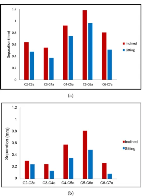
The largest separations were at 10˚ and they gradually turned to negative as the traction angle increased. In all cases, the segment C5-C6 was extended the most, followed by the segment C4-C5 and then C6-C7. Overall, the inclined position achieved larger separation and lower compression. The posterior measurements are presented in Figure 9. Again, the segment C5-C6 achieved the highest sepa-ration, followed by C4-C5 and C6-C7. The inclined position is found to achieve larger separations than the sitting position. Furthermore, at 40˚, the segment C6-C7 in the sitting position achieved the smallest separation.
3.3. Traction Angles and Traction Forces
(a)
[image:10.595.258.490.65.382.2](b)
Figure 9. Posterior intervertebral separations at 10˚ (a) and 40˚(b).
4. Discussion
(a)
(b)
Figure 10. Traction angle vs Force on anterior in sitting (a) and inclined (b) position.
60N, there was very little force to pull the head upward. As the body leaned for-ward in the sitting position scenario, both the anterior and posterior sides be-came compressed. Another interesting observation was that the anterior separa-tions reached −6mm in the sitting position at 40˚ in Figure 4, indicating a sub-stantial compression on the anterior side. In contrast, the inclined position only showed a 2 mm compression under the same condition. On the posterior side, the inclined position was able to achieve a larger separation in all combinations of angles and forces. This may be an indication that the sitting position was adding too much pressure on the anterior side and yet not able to achieve the expected result. Overall, our result suggested that using the inclined position provides a larger separation in both the anterior and posterior sides compared to the sitting position.
(a)
[image:12.595.248.506.64.398.2](b)
Figure 11. Traction angle vs force on posterior in sitting (a) and inclined (b) position.
5. Conclusion
References
[1] Haldeman, S., Carroll, L. and Cassidy, J. (2008) The Empowerment of People with Neck Pain: Introduction: The Bone and Joint Decade 20002010 Task Force on Neck Pain and Its Associated Disorders. Spine, 33, S8-S13.
https://doi.org/10.1097/brs.0b013e3181643f51
[2] Judovich, B. and Nobel, G.R. (1957) Traction Therapy, a Study Resistance Forces.
The American Journal of Surgery, 93, 108-114.
https://doi.org/10.1016/0002-9610(57)90748-1
[3] Hogg-Johnson, S., Van Der Velde, G., et al. (2008) The Burden and Determinants of Neck Pain in the General Population: Results of the Bone and Joint Decade 2000- 2010 Task Force on Neck Pain and Its Associated Disorders. European Spine Jour-nal, 33, S39-S51. https://doi.org/10.1097/BRS.0b013e31816454c8
[4] Savva, C. and Giakas, G. (2013) The Effect of Cervical Traction Combined with Neural Mobilization on Pain and Disability in Cervical Radiculopathy. A Case Re-port. Manual Therapy, 18, 443-446. https://doi.org/10.1016/j.math.2012.06.012
[5] Zylbergold, R. and Piper, M. (1985) Cervical Spine Disorders: A Comparison of Three Types of Traction. Spine, 10, 867-871.
https://doi.org/10.1097/00007632-198512000-00001
[6] Jellad, A., Ben Salah, Z., Boudokhane, S., Migaou, H., Bahri, I. and Rejeb, N. (2009) The Value of Intermittent Cervical Traction in Recent Cervical Radiculopathy. An-nals of Physical and Rehabilitation Medicine, 52, 638-652.
https://doi.org/10.1016/j.rehab.2009.07.035
[7] van der Heijden, G.J., Beurskens, A.J., Koes, B.W., Assendelft, W.J., de Vet, H.C. and Bouter, L.M. (1995) The Efficacy of Traction for Back and Neck Pain: A Syste-matic, Blinded Review of Randomized Clinical Trial Methods. Physical Therapy, 75, 93-104. https://doi.org/10.1093/ptj/75.2.93
[8] Harte, A., Baxter, G. and Gracey, J. (2003) The Efficacy of Traction for Back Pain: A Systematic Review of Randomized Controlled Trials. Archives of Physical Medicine and Rehabilitation, 84, 1542-1553.
https://doi.org/10.1016/S0003-9993(03)00294-6
[9] Daniel, D.M. (2007) Non-Surgical Spinal Decompression Therapy: Does the Scien-tific Literature Support Efficacy Claims Made in the Advertising Media? Chiroprac-tic & Osteopathy, 15, 7. https://doi.org/10.1186/1746-1340-15-7
[10] Coutinho, M.G. (2001) Dynamic Simulations of Multibody Systems. Springer, New York. https://doi.org/10.1007/978-1-4757-3476-8
[11] Merrill, T., Goldsmith, W. and Deng, Y.C. (1984) Three-Dimensional Response of a Lumped Parameter Head-Neck Model Due to Impact and Impulsive Loading.
Journal of Biomechanics, 17, 81-95. https://doi.org/10.1016/0021-9290(84)90126-X
[12] Ahn, H. and DiAngelo, D. (2008) A Biomechanical Study of Artificial Cervical Discs Using Computer Simulation. Spine, 33, 883-892.
https://doi.org/10.1097/BRS.0b013e31816b1f5c
[13] Wong, L.K., Luo, Z., Kurusu, N. and Fujino, K. (2013) Cervical Spine Simulation Model for Traction Therapy Analysis. Proceedings of the 2013 IEEE/SICE Interna-tional Symposium on System Integration, Kobe, 15-17 December 2013, 516-520.
https://doi.org/10.1109/SII.2013.6776747
[14] Wong, A., Leong, C. and Chen, C. (1992) The Traction Angle and Cervical Inter-vertebral Separation. Spine, 17, 136-138.
https://doi.org/10.1097/00007632-199202000-00003
Po-sitions Cervical Traction on Cardiovascular Parameters, Pain and Neck Mobility in Patients with Cervical Spondylosis. The Internet Journal of Rheumatology, 8, 1-11.
http://ispub.com/IJRH/8/1/1461
[16] Fater, D.C.W. and Kernozek, T.W. (2008) Comparison of Cervical Vertebral Sepa-ration in the Supine and Seated Positions Using Home Traction Units. Physiothe-rapy Theory and Practice, 24, 430-436. https://doi.org/10.1080/09593980802511896
[17] BodyParts3D/Anatomography. Copyright 2008. Database Center for Life Science, Licensed by CC-BY-SA-2.1-jp. http://lifesciencedb.jp/bp3d/?lng=en
[18] Blender 2.75 [Computer Software] (2015). https://www.blender.org/
[19] De Leva, P. (1996) Adjustments to Zatsiorsky-Seluyanov’s Segment Inertia Parame-ters. Journal of Biomechanics, 29, 1223-1230.
https://doi.org/10.1016/0021-9290(95)00178-6
[20] Vortex Dynamics 3.0 [Computer software] (2008). http://www.cm-labs.com/ [21] Ito, F. and Kiyama, T. (1985) Angular Factor in Intermittent Cervical Traction [頚
椎間歇牽引における角度因子]. Sogo Rehabilitation [総合リハビリテーション],
13, 213-218.
Submit or recommend next manuscript to SCIRP and we will provide best service for you:
Accepting pre-submission inquiries through Email, Facebook, LinkedIn, Twitter, etc. A wide selection of journals (inclusive of 9 subjects, more than 200 journals)
Providing 24-hour high-quality service User-friendly online submission system Fair and swift peer-review system
Efficient typesetting and proofreading procedure
Display of the result of downloads and visits, as well as the number of cited articles Maximum dissemination of your research work
Submit your manuscript at: http://papersubmission.scirp.org/