warwick.ac.uk/lib-publications
Manuscript version: Author’s Accepted Manuscript
The version presented in WRAP is the author’s accepted manuscript and may differ from the published version or Version of Record.
Persistent WRAP URL:
http://wrap.warwick.ac.uk/129598
How to cite:
Please refer to published version for the most recent bibliographic citation information. If a published version is known of, the repository item page linked to above, will contain details on accessing it.
Copyright and reuse:
The Warwick Research Archive Portal (WRAP) makes this work by researchers of the University of Warwick available open access under the following conditions.
Copyright © and all moral rights to the version of the paper presented here belong to the individual author(s) and/or other copyright owners. To the extent reasonable and
practicable the material made available in WRAP has been checked for eligibility before being made available.
Copies of full items can be used for personal research or study, educational, or not-for-profit purposes without prior permission or charge. Provided that the authors, title and full
bibliographic details are credited, a hyperlink and/or URL is given for the original metadata page and the content is not changed in any way.
Publisher’s statement:
Please refer to the repository item page, publisher’s statement section, for further information.
Abstract—In this paper, a new security and green communication scheme is proposed to the Interference-Alignment (IA) based networks. To achieve a secured communication, full-duplex receivers are utilized to transmit artificial noise (AN). Both the signals and the ANs are used to harvest energy to realize green communication. For these reasons, the feasible conditions of this scheme are analyzed first. Secondly, the average transmission rate, the secrecy performance and the harvested energy are investigated. Thirdly, an optimization scheme of simultaneous wireless information and power transfer (SWIPT) is given to optimize the information transmission and the energy harvesting efficiency. Meanwhile, an improved IA iteration algorithm is designed to eliminate both the AN and the interference. Furthermore, relay cooperation is considered and its system performance is analyzed. The simulations show that the target average transmission rate is not affected by AN, while the secrecy performance can be greatly improved. The energy harvesting efficiency is also better than the traditional schemes. As expected, the average transmission rate further is improved with the relay cooperation.
Index Terms—Artificial noise (AN), eavesdropping, interference alignment (IA), relay, secrecy, simultaneous wireless information and power transfer (SWIPT)
I. INTRODUCTION
HE broadcast characteristics of the wireless
communication networks (WCNs) determine that it is an open communication environment. The sharing of its information medium leads to intricate electromagnetic radiation problems. Of these, multi-user interference, wireless transmission secrecy and radio signal enabled wireless power transfer are intensively discussed in these WCNs [1]-[3].
Interference exists widely in multi-user WCNs, and this affects multiplexing rate of time slots, frequencies, and code space, which severely limits the reusability of channel resources and reduces the spectrum of networks. It has become
Manuscript received April 06, 2019.
This work was supported in part by the National Natural Science Foundation of China (NSFC) under Grant 61871203, 61401180, 61371114 and the Natural Science Fund of the Jiangsu Higher Education Institutions under Grant 13KJB510007.
Zhibin Xie, Xinquan Geng, Benjamin Panful, Yajun Wang, Yinjie Su, Zhenkai Zhang, and Ying Hu are with the School of Electronic and Information, Jiangsu University of Science and Technology, Zhenjiang, China (e-mail: [email protected]).
Yunfei Chen is with the School of Engineering, University of Warwick, Coventry, UK (e-mail: [email protected]).
Kening Song is with the PLA AF 95829, Xiaogan, China (e-mail: [email protected])
the bottleneck of system capacity enhancement. With the increase of users and data services in WCNs, conventional interference management methodologies either have difficulty in achieving good interference cancellation and suppression effects or have achieved the purpose of interference at the expense of network capacity. In recent years, the emergence of interference alignment (IA) technology has subverted the traditional understanding of the upper limit of communication network capacity in the academic community [4]-[6], and many
researches have shown that IA can significantly improve the system’s degree of freedom and can be applied to many kinds of multiuser WCNs with excellent performance [7], [8].
Also, personal privacy and security have become important requirement in the design of communication networks as a result of the growth of mobile data services. However, convenient wireless communications face more serious security problems than wired communications because, the open channel and the eavesdropping characteristics of the former are major security threats to wireless communication. Traditional cryptography-based privacy algorithms have been challenged with the development of high-performance processors. Hence, many efforts have been made to secure the communications.
The physical layer security is intended to limit the achievable information at the physical layer. In particular, the pioneering work at physical layer was firstly demonstrated by Wyner [8]. Subsequently, for realizing information security transfer, the physical layer security technology, notably artificial noise (AN), beamforming, and phase rotation were received much concern in different communication scenarios [10]-[28]. By utilizing the property of wireless channel and the idea of random coding, the information flow is hidden in the external noise in the eavesdropping channel, and as a result, the information cannot be obtained by the eavesdropper [10], [11]. In all kinds of methods, AN is an intuitive and effective method to realize communication security [12]-[14]. Beamforming can maximize the power of jamming signal to hide the desired signal from a potential eavesdropper, while maintaining a prespecified SINR at the desired receiver [15], [16], [19]. For eavesdropper with massive antenna, transmitters randomly rotate the phase of original symbols to interrupt eavesdropper, and the legitimate users are able to take proper inverse operations to recover the received signals [17]. As helper, relay can improve communication security in the presence of eavesdropper, especially when the source-destination channel is worse than the source-eavesdropper channel [18], [19], [23], [27], [52]. Besides that, some typical secure communication
Secured Green Communication Scheme for
Interference Alignment Based Networks
Zhibin Xie, Member, IEEE, Xinquan Geng, Yunfei Chen, Senior Member, IEEE, Kening Song, Benjamin
Panful, Yajun Wang, Yinjie Su, Zhenkai Zhang, Ying Hu
approaches are proposed for special network scenario, such as wireless ad-hoc network, ultra-dense network, social network and cognitive radio system [20]-[23]. In addition, full duplex receiver is a forthcoming technique which acts as a jammer and a receiver, and eliminates the need for external helpers and provides system robustness [24]-[28].
However, self-interference is one of the key challenges faced in designing practical full-duplex transceivers. Fortunately, we can use aforementioned IA-based network intrinsic property adequately, and combine many techniques have been developed to suppress the self-interference [25]. For secure communications, we adequately exploit IA network in this paper, and make use of AN to realize physical layer security. Our object is to investigate the achievable performance of the IA-based network. Whereas it is such a full of electromagnetic interference environment, we should consider the dual character of electromagnetic radiation further.
Since communications have been integrated into all aspects of our daily lives, the energy efficiency problem has become increasingly prominent in “green” WCNs [29], [30]. Especially, for wireless communications, effective energy supply is needed for all kinds of mobile terminals in mobile communication. Therefore, the concept of wireless powered communication (WPC) was raised [31], [32]. In fact, with the advent of collecting energy methods using radio frequency (RF) signals, WPC have caused extensive research and attention [33]-[42]. In these studies, the authors studied the sustainability analysis of WPC and the relation between interference and energy harvesting in [35]-[37]. Moreover, researchers found that the wireless power transfer process can be used in some wireless service such as secure wireless communications [16], [19], [38]-[42]. Motivated by these literature analyses, we believe that it is necessary to analyze the coexisting performance, which is the secure transmission for wireless information and power transfer in IA-based MIMO network using full-duplex jamming receivers.
In summary, the interference in a WCN is a mixed blessing [37], [43]-[46], [53]. In particular, for an IA-based network, the interferences can not only be used as energy source in [44], but also can be used to distract the eavesdropper in [45]. However, if antennas are equipped at the eavesdropper adequately, the inherent interference will still be eliminated. In order to ensure the security of information transmission, Ruan et al proposed a scheme for IA-based network by utilizing jammers to transmit AN [47], [48]. On this basis, in [49], transmitters were used to transmit AN to achieve security, where the AN and signal from a certain user-pair are in the same channel. This scheme uses zero-forcing (ZF) of ANs and thus, it affects the designs of precoding and decoding, and reduces the transmission rate. Moreover, the improvement of the secrecy performance is not prominent, this is because that the ANs can also be eliminated by the eavesdropper except for target users. Thus far, although interference management, secure and green communication have had many excellent researches, the combination of the three areas is often ignored. Especially, with the rapid development of wireless communication technology in recent years, these three thorny problems are aggravated in the design
of wireless communication systems. Thus, a thorough and comprehensive analysis of interference, security, and EH problems is of great significance.
In order to improve the anti-eavesdropping performance and energy harvesting efficiency in an IA-based network simultaneously, in this paper, we propose a new scheme to achieve secure communication by using full-duplex receivers to transmit AN in an IA-based network, and to harvest the energies of signal and AN. The feasible conditions are analyzed. In the proposed scheme, since the AN and the signal from a certain user-pair are in the different channels and are independent of each other, the designs of precoding and decoding will not be affected by the ZF of ANs compared with previous work, and thus the average transmission rate are guaranteed. While the ANs from receivers cannot be eliminated by the eavesdropper and the anti-eavesdropping performance is improved. Also, the energy harvesting efficiency is improved by the introduced AN. Then, the relay technology is also considered for the proposed IA-based scheme based on AN transmitted by the receiver. After the relay node joins in the scheme, average transmission rate is further improved.
The main contributions of this paper are summarized as follows.
1) A new scheme is proposed to realize secure communication in an IA-based network. In this scheme, full-duplex receivers are used to transmit AN, the residual self-interference problem of full-duplex device is solved effectively by IA. Nevertheless, the AN cannot be eliminated at the eavesdropper.
2) The feasible conditions of IA and the anti-eavesdropping performance are analyzed. If IA is feasible, all the ANs transmitted by receivers can be used to disturb the eavesdropper, which can largely improve the secrecy performance.
3) An improved IA iteration algorithm is proposed in this paper, and the zero-forcing operation of the AN and the interference are simultaneously considered in the proposed algorithm.
4) An optimization scheme is proposed to optimize energy harvesting and information transmission.
5) System performance is analyzed after the relay node joins. The average transmission rate is obviously improved with the cooperation of relay.
method based on the proposed scheme is given. In Section V, we studied the relay technology and joined the relay in the proposed scheme, then introduced the IA iteration algorithm in the case of joining the relay node. In Section VI, we presented the simulation results and analyzed the performance of our proposed scheme. Finally, conclusions and further work are given in Section VII.
Notation:
H
( ) denotes conjugate transpose,
[ ] i
V is the eigenvector which corresponds to the ith smallest eigenvalue of a matrix,
( )i, ( )*i are the ith column and the ith row of a matrix,
respectively,
N M
is a space of N M matrices,
N
I is N N identity matrix,
M N
0 is M N zero matrix.
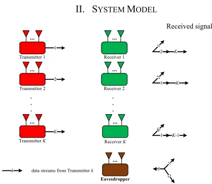
II. SYSTEM MODEL
Consider a typical K-user IA-based network with an external eavesdropper as shown in Fig. 1. The eavesdropper only receives data, and thus legitimate users can not know the existence of eavesdropper.
A. Typical IA-based network
Assume that transmitter k has M[k] antennas and transmits d[k]
data streams, receiver k has N[k] antennas, k1, 2,3,...,K. The
signal at receiver k can be expressed as
H H H
[ ] [ ] [ ] [ ] [ ] [ ] [ ] [ ] [ ] [ ] [ ] 1,
, K
k k kk k k k kj j j k k
j j k
y U H V x U H V x U n (1)
where x[k] is the signal vector containing d[k] data streams
transmitted by transmitter k with power P[ ]k , [ ] [ ]
[ ]
k k M d k
V
and [ ] [ ]
[ ] k k N d k
U are the unitary precoding matrix and
unitary interference suppression matrix, respectively, so that
[ ]
H
[ ] [ ]k k dk
V V I , H [ ]
[ ]k [ ]k dk
U U I . Assume that the channel
estimations are perfect for legitimate transceivers.
[ ] [ ]
[ ]
j k N M kj
H is the channel matrix from transmitter j to
receiver k, and its elements follow independent and identically
distributions, [ ]1
2
[ ] 0,
k N
k N
n I is the additive
white Gaussian noise (AWGN) vector at receiver k.
In order to obtain the desired signal, it is necessary to eliminate all the interferences from other users, thus the following conditions must be satisfied.
[ ] [ ]
H
[ ]k [ ] [ ]ki i dkdk , i k,
U H V 0 (2)
H
[ ] [ ] [ ] [ ]
rank(U H Vk kk k )dk, k 1, 2, , . K (3) When condition (2) and (3) are satisfied, we call the IA-based network feasible. The transmission rate of receiver k
can be expressed as [44]
H H H
[ ] 2 2 [ ] [ ] [ ] [ ] [ ] [ ] [ ] 1
log .
t k d k kk k k k kk k R
I U H V S V H U (4)
where S[k] indicates the covariance matrix of the signal
transmitted by transmitter k.
B. Feasible Conditions of IA
The feasible conditions of IA are analyzed in [50]. The IA-based network itself is equivalent to a polynomial system. For a polynomial system, it can be solved only when the number of variables is larger than or equal to the number of equations. Thus, the feasibility of an IA-based network usually depends on the number of antennas from each user and the number of data streams transmitted by transmitter. Here, we can directly utilize the conclusions about the number of equations and variables in [50].
That is, for an IA-based network shown in Fig.1, the number of equations in condition (2) and (3) can be expressed as
E [ ] [ ]
, 1,2, ,
,
k i k i K k i
N d d
(5)
The number of variables can be expressed as
V [ ] [ ] [ ] [ ] 1
( 2 ).
K
k k k k
k
N d M N d
(6)In order to simplify in this paper, all the parameters of the user are set to the same, that is, M[ ]k M, N[ ]k N, d[ ]k d
and P[ ]k P. If and only if NVNE, IA is feasible, which is
2
( 2 ) ( 1),
dK M N d d K K (7) After simplification, we can get
. 1 M N d
K
(8)
C. Eavesdropper
When an external eavesdropper with Ne antennas exists in
the IA-based network as shown in Fig. 1, it is assumed that the channel state information (CSI) between transmitter and eavesdropper is known by the eavesdropper, but the CSI between transmitter and receiver is unknown. The received signals of target user k at the eavesdropper can be expressed as
H H H
e[ ] e[ ] te[ ] [ ] [ ] e[ ] te[ ] [ ] [ ] e[ ] e 1,
+ K
k k k k k k j j j k
j j k
,y U H V x U H V x U n (9)
where Ue[k] is the decoding matrix at the eavesdropper, Hte[k] is
the channel matrix from transmitter k to the eavesdropper, and
ne is the AGWN vector at the eavesdropper. In order to obtain the information from the target user, the interferences from
Transmitter 1
。 。 。
。 。 。
1
2
K
1
2 K
2
1 K
K
1 K-1
k
2 1
k data streams from Transmitterk
Received signals
TransmitterK
Transmitter 2
Receiver 1
Receiver 2
Receiver K
[image:4.612.57.268.269.452.2]Eavesdropper
other users should be eliminated. That is, the following condition must be satisfied.
H
e[ ]k te[ ] [ ]j j 1d, j k.
U H V 0 (10)
Therefore, the number of antennas at the eavesdropper must meet Proposition 1 proposed in [49]. Assume that enough antennas are equipped at the eavesdropper, although the eavesdropper can eliminate the interferences from other users, the interference between data streams from the target user still exists. Thus, (9) can be re-expressed as
H H
e[ ] e[ ] te[ ] [ ] [ ] e[ ] e
H H
e[ ] te[ ] [ ] [ ] e[ ] e 1
( ) ( ) .
k k k k k k
d
k k k i k i k i
y U H V x U n
U H V x U n (11)
Then, the eavesdropping rate of user k at the eavesdropper can be expressed as
H H H
e[ ] te[ ] [ ] [ ] [ ] te[ ] e[ ]
e[ ] 2
2 H H H
1
e[ ] te[ ] [ ] [ ] [ ] te[ ] e[ ] 1,
( ) ( )
log (1 ).
( ) ( )
d
k k k i k k i k k
k d
i
k k k j k k j k k j j i
R
U H V S V H U
U H V S V H U
(12)
D. SWIPT analysis
For the IA-based network as shown in Fig. 1, power splitting (PS) scheme and antenna selection (AS) scheme can be applied to harvest energy.
1) PS scheme:The idea of power splitting refers to that the received signal at the receiver is divided into two parts after passing through the power splitting device: one part is used for information transmission, and the other part is used for energy harvesting. In this mode, the transmitter’s information and energy are transmitted at the same time, frequency, and space resources.
2) AS scheme: In energy harvesting networks, AS scheme can be considered as a special case of PS schemes. At the receivers with multiple antennas, the energy harvesting and information transmission are implemented on different antennas, and a part of the antenna is selected for energy harvesting. The remaining antennas are used for information transmission.
III. PROPOSED SECURE COMMUNICATION SCHEME
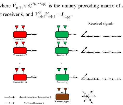
A. IA-based network with AN transmitted by receiver
Using transmitters to transmit AN decreases transmission rate, because the AN and signal from a certain user-pair are in the same channel. In order to ensure the performance of rate and secrecy simultaneously, we propose a new scheme which uses full-duplex receivers to transmit AN in IA-based network, as shown in Fig. 2. Assume that z[k] is the AN vector containing
dan[k] data streams transmitted by receiver k with transmission
power Pan[k], r[ ] [ ] [ ]
k j N N kj
H is the channel matrix from
receiver j to receiver k, and follows independent and identically Rayleigh distribution, and the channel estimations between receiver and receiver are also perfect. Thus, the received signals at receiver k is
H H H
[ ] [ ] [ ] [ ] [ ] [ ] [ ] [ ] [ ] [ ] r[ ] an[ ] [ ]
1, 1,
H H
[ ] r[ ] an[ ] [ ] [ ] [ ]
+
+
K K
k k kk k k k kj j j k kj j j
j j k j j k
k kk k k k k
,
y U H V x U H V x U H V z
U H V z U n
(13)
where [ ] an
an[ ]
k k N d k
V is the unitary precoding matrix of AN
at receiver k, and H an
an[ ] an[ ]k k d k
V V I .
To obtain the desired signal at receiver k, the following conditions should be satisfied simultaneously
[ ] [ ]
[ ] an
H [ ] [ ] [ ]
H
[ ] [ ] [ ] [ ] H
[ ] r[ ] an[ ]
, ,
rank( ) , 1, 2, , ,
, , 1, 2, , , k k
k k k kj j d d
k kk k k k kj j d d
j k
d k K
j k K
U H V 0
U H V
U H V 0
(14)
In order to simplify, several parameters of the users are set to the same from now on, that is, dan[k]=dan and Pan[k]=Pan. Since the
IA-based network is equivalent to a polynomial system [50], if an IA-based network shown in Fig. 2 is feasible, it should meet Lemma 1.
Lemma 1: For the proposed scheme, in order to make IA feasible, the numbers of antenna and data stream must satisfy
2 2 2
an an an
( ) ,
.
dM d d N d d d K dd K d M d N
(15)
Proof: The number of variables in (14) can be expressed as
V ( 2 ) an ( an),
C dK M N d d K N d (16) and the number of equations can be expressed as
2 2
E ( 1) an .
C d K K dd K (17) Thus, from CV CE, one has
2 2 2
an an an
( ) .
dM d d Nd d d K dd K (18) Also, the number of information data streams cannot be greater than the number of antennas at the receiver and the transmitter. That is,
.
d Md N (19)
Therefore, if the IA-based network is feasible, it must satisfy (18) and (19). ■
[image:5.612.317.553.49.251.2]Since the radio link resources are usually more valuable than energy resources, it is reasonable to set the number of AN data streams as 1, Thus, the (18) can be rewritten as (20).
Fig. 2. K-user IA-based network of AN transmitted by receiver with an external
H H H e[ ] te[ ] [ ] [ ] [ ] te[ ] e[ ]
e[ ] 2
2 H H H H H H
1
e[ ] te[ ] [ ] [ ] [ ] te[ ] e[ ] e[ ] re[ ] an[ ] an[ ] re[ ] e[ ]
1, 1
( ) ( )
log 1+
( ) ( ) + ( ) ( )
d
k k k i k k i k k
k d K
i
k k k j k k j k k an k k k i k i k k
j j i s
R
P
U H V S V H U
U H V S V H U U H V V H U
(29)
2 2
( 1) 1.
dM d Nd K dK d (20) Also, considering that the AN transmitted by receiver and the signal transmitted by transmitter are through independent channels, the ZF operations of AN won’t affect the precoding matrix V and decoding matrix U. Thus, after IA is performed, the transmission rate of receiver k can be expressed as
H H H
t[ ] 2 2 [ ] [ ] [ ] [ ] [ ] [ ] [ ]
1
log .
k d k kk k k k kk k
R
I U H V S V H U (21)
When the CSI between receiver and eavesdropper is unknown at the eavesdropper, the most appropriate way of the receiver is to send Gaussian white noise with the same band of transmitting signal. Thus, the received signals at the eavesdropper can be rewritten as
H H H H
e[ ] e[ ] te[ ] [ ] [ ] e[ ] te[ ] [ ] [ ] e[ ] re[ ] an[ ] [ ] e[ ] e
1, 1
+ + .
K K
k k k k k k j j j k j j j k
j j k j
y U H V x U H V x U H V z U n
(22)
where re[ ] Ne N
k
H is the channel matrix from receiver k to
the eavesdropper. Although the feasible condition of eavesdropper in Fig. 2 which looks like the appearance of Proposition 1 in [49], we have to state Lemma 2 for the proposed scheme, because the new model induces an extra AN term in (22), which makes eavesdropper unable to eradicate the AN from other users and thus improves secrecy performance.
Proposition 1: Consider an IA-based network which satisfies (18) and (19) as shown in Fig. 2, the interferences from other users can be eliminated at the eavesdropper, if at least (dK-d+1) antennas are used at the eavesdropper.
Proof: In order to cancel the second term of (22), the total number of equations can be expressed as
e
E ( 1).
C d K (23)
As the precoding matrices are determined by the legitimate transmitters in the network, the number of variables can be expressed as
e
V= e 1.
C N (24)
According to Lemma 1, the eavesdropper considers its IA feasible only when
e 1.
N dK d (25)
Here, since the AN transmitted by receiver is just white noise, the CSI between receiver and eavesdropper will not be estimated at the eavesdropper and the ANs cannot be eliminated. Thus, the interference covariance matrix estimated by the eavesdropper can be expressed as
H H e[ ] te[ ] [ ] [ ] te[ ]
1, K
k j j j j
j j k P d
Q H V V H , (26)
and the decoding matrix at the eavesdropper can be expressed as
e[ ]k V1[ e[ ]k],
U Q (27)
where V1[ ] is the eigenvector which corresponds to the first smallest eigenvalue of matrix Qe[k].
After the interferences from other users are eliminated, the remaining signal at the eavesdropper is
H H H
e[ ] e[ ] te[ ] [ ] [ ] * e[ ] re[ ] an[ ] [ ] e[ ] e
1 1
( ) ( ) .
d K
k k k k i k i k j j j k
i j
y U H V x U H V z U n (28)
Then, the eavesdropping rate of user k can be expressed as (29). From (29) we can see that all the ANs from receivers can be used to distract the eavesdropper and the eavesdropping rate can be decreased by increasing the transmission power of AN to make secure communications possible.
B. Iterative Algorithm
For full-duplex devices, the self-interference is an annoying thing. In order to solve self-interference problem, antenna cancellation, radio frequency offset, and digital signal processing can be used to reduce the self-interference to an acceptable level, then we propose an improved iterative IA algorithm to align the interference of the other users, the remaining self-interference and the AN into the interference space. As in [51], we consider a reciprocal network in this section to implement the IA-based communication in Fig. 2. Each user aims at minimizing their own interference leakage. For user k, its interference leakage is Ie k[ ]trace
U Q U[ ]Hk [ ]k [ ]k
where Q[k] is the interference covariance matrix of user k. The
pseudo-code of the proposed iterative algorithm is as follows.
Algorithm 1: IA iteration algorithm with AN transmitted by receiver
1. Initialize the precoding matrix V[ ]j and Van[ ]j , 1, 2, , .
j K 2. Begin iteration
3. Calculate the interference covariance matrix Q[ ]k , which contains both interference of other users and ANs
H H H H
[ ] [ ] [ ] [ ] [ ] [ ] r[ ] an[ ] an[ ] r[ ]
1, 1
.
K K
k ki i i i ki an kj j j kj
i i k j
P
Q H V S V H H V V H
4. Calculate the decoding vector U[ ]k ,
[ ] [ ] 1 [ ] 2 [ ]
[ ] [ ]
[( ) , ( ) , , ( ) ], 1, 2, , ,
( ) [ ], 1, 2, , ; 1, 2, , .
k k k k d
k i i k
k K
V i d k K
U U U U
5. Set [ ]k
V as the precoding matrix in the reciprocity network,
[ ]k [ ]k,k1, 2, , .K
V U
6. Calculate the interference covariance matrix in the reciprocity network [ ]k
Q and w[ ]k
Q ,
H H [ ] [ ] [ ] [ ]
[ ] [ ]
1,
H H r[ ] [ ] [ ] r[ ]
w[ ] [ ]
1
= ,
.
K
ki i i ki
k i
i i k K
kj j j kj
k j
j
Q H V S V H
Q H V S V H
7. Calculate the decoding matrix [ ]k
U in the reciprocity network,
[ ]k [( [ ]k ) , (1 [ ]k ) , , (2 [ ]k ) ],d k1, 2, , ,K
U U U U
[ ] [ ]
( k )i Vi[ k ],i1, 2, , ;d k1, 2, , .K
U Q
8. Calculate the precoding matrix of AN Van[ ]k ,
w[ ]
an[ ]k V1[ k],k1, 2, , .K
V Q
9. Reverse the direction, and set [ ]k
U as the precoding matrix [ ]k
V .
10.Calculate the interference leakage, if the difference between this iteration and the last iteration is less than the threshold, the interference leakage convergence and end the iteration. Otherwise, return to step 3.
where [ ]ij [ ]Hji, r[ ]ij r[ ]Hji, and [ ]k [ ]k
H H H H V U . Similarly to
[51], the proposed iterative algorithm also is convergent.
However, if residual self-interference exists, the proposed algorithm needs more iterations compared with [49].
IV. SWIPT OPTIMIZATION SCHEME WITH AN
Energy efficiency is a key factor to be considered in green communication network. Especially, in the proposed scheme, the AN can be used not only for physical layer security but also for energy harvesting. Consequently, in order to improve the energy efficiency and transmission rate for proposed scheme, SWIPT optimization is presented in this section.
A. Conventional SWIPT scheme
For the multi-user MIMO system shown in Fig. 1, we firstly discuss the conventional SWIPT scheme based on [3], [49].
1)AS scheme: Assuming that each receiver is equipped with
N antennas, and L antennas are selected for information decoding, the remaining antennas are used to harvest energy, and L must satisfy
L M
K1
d.For information transmission, we assume that the interference can be completely eliminated by IA, the transmission rate of receiver k can be expressed as
H H H
[ ] 2 2 [ ] [ ] [ ] [ ] [ ] [ ] [ ]
1 log
AS k d k kk k k k kk k R
I U D V S V D U , (30)
where [ ] L M
ki
D is the channel matrix for information
transmission from transmitter i to receiver k, which is composed of L rows of Hki.
In terms of energy harvesting, since the remaining antennas
are used to harvest energy, assuming that ( )
[ ]ki N L M
F is
the channel matrix for energy harvesting from transmitter i to
receiver k, which is composed of the remaining N-L rows of
ki
H . The energy harvested by receiver k can be expressed as
H H [ ] [ ] [ ] [ ] [ ] [ ]
1
Tr(K ( ))
AS k ki i i i ki i
E
F V S V F , (31)where is the loss of energy converted to electrical energy during energy harvesting and is a constant.
Since each receiver selects L antennas for information transmission, there exists
L KN
C antenna combining modes.
For a certain scenario, there has to be a unique combination to make the AS scheme optimal. Assume that all CSI is known at the receiver, the optimization problem can be expressed as
1, , 1 [ ] [ ]
max ( (1 ) )
s.t. Tr P, 1, , ,
0, 1, ,
K K
k AS k k AS k k
k k
R E
k K
k K
S S
S S
,
(32)
where 0k 1 is the power configuration weights for information transmission at receiver k. is a constant in a unit of bit/Joule. For a given k, the above optimization problem can be divided into K independent subspace problems,
[ ] [ ]
max 1- , 1, ,
s.t. Tr , 0.
k k AS k k AS k
k k
R E k K
P
S
S S (33)
It can be found that for receiver k, the above optimization problem is a convex problem that can be solved by convex optimization.
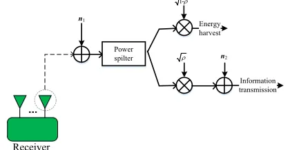
2) PS scheme: We assume that each antenna of each receiver can simultaneously harvest energy and transmit information through a power splitting device, and the power splitting device
is as shown in Fig. 3, where 1 2
1 (0, 1 )
N
N CN
n I and
1 2
2 (0, 2 )
N
N CN
n I denote the path noise and antenna
noise of the receiver respectively, and ρis the splitting ratio.
Specifically, let kj denote the power distribution ratio for information transmission at the jth antenna of receiver k,
0kj 1,k1, 2,, ;K j1, 2,,N.
In terms of information transmission, the transmission rate of receiver k can be expressed as
1H 1/2 1/2 H 1/2 2 1/2 2
PS[ ]k log2 d [ ]k [ ]k 1[ ]k [ ]k [ ]k [ ]k [ ]k 1 N 2[ ]k [ ]k 2 N [ ]k ,
R I U C Q C U U C I Q C I U
(34)
Receiver
Power spilter
Information transmission
n1
n2
Energy harvest
1-
[image:7.612.332.542.403.512.2]
where C[ ]k diag
k1, k2,, kN
is the powerdistribution diagonal for information transmission of all the antennas at receiver k. When it is equal power distribution among different antennas at receiver k, the C[k] can be rewritten
as C[ ]k diag
k, k, , k
, 1[ ] [ ] [ ] [ ] [ ] [ ] H H k kk k k k kQ H V S V H ,
2[ ] [ ] [ ] [ ] [ ] [ ] 1,
K
H H k kl l l l kl
l l K
Q H V S V H . If the interference is complete
alignment, the (34) can be rewritten as
H H H
PS[ ] 2 2 2 [ ] [ ] [ ] [ ] [ ] [ ] [ ]
1 2
log .
k d k kk k k k kk k
R
I U H V S V H U (35)
In terms of energy harvesting, the harvested energy at receiver k can be expressed as
H H PS[ ] [ ] [ ] [ ] [ ] [ ] [ ]
1
Tr(K ( ))
k k ki i i i ki
i
E
C H V S V H , (36)where C[ ]k INC[ ]k . There is also a unique power allocation ratio for a scenario to make the PS scheme optimal. Therefore, its optimization problem can be expressed as
1, ,[ ] 1 PS[ ] PS[ ]
[ ]
max ( (1 ) )
s.t. 0 1, 1, ,
K K
k k k k
k k
R E
k K
C C (37)
Similarly, the above problem can be decomposed into K
independent subspace problems, and then the convex optimization methods can be used to find the optimal solution.
B. New SWIPT Optimization Scheme with AN
For the proposed scheme model as shown in Fig. 2, we consider SWIPT optimization algorithm to harvest the energy both from signals and ANs simultaneously. Because radio link resource is more expensive, we only adopt the PS scheme to optimal energy harvesting and information transmission in this section.
Under this condition, the interference-free transmission rate at receiver k is
H H H
PS[ ] 2 2 2 [ ] [ ] [ ] [ ] [ ] [ ] [ ]
1 2
log .
k d k kk k k k kk k
R
I U H V S V H U (38)
Because there are ANs, the harvested energy at receiver k is
H H H H
PS[ ] [ ] [ ] [ ] [ ] [ ] [ ] an[ ] an[ ] an[ ] an[ ] an[ ] 1
Tr K + .
k k ki i i i ki ki i i i ki
i
E
C H V S V H H V S V H (39)
Thus, the optimization problem can be described as
1, ,[ ] 1 PS[ ] PS[ ]
[ ]
max ( (1 ) )
s.t. 0 1, 1, ,
K K
k k k k
k k
R E
k K
C C (40)
The objective function (40) can be decomposed into sub-objective functions of K independent subspaces. The power distribution index is henceforth suppressed to avoid cumbersome notation, therefore, the kth sub-objective function can be expressed as
PS[ ] (1 ) PS[ ] s.t. 0 1k k k k
f R E
(41)
The optimal power distribution ratio ρ can be solved according to the interior point method. The optimization algorithm is as follows
Algorithm 2: Interior point optimization method
1.Construct a penalty function
,r
=f rln 1-
; 2.Initialize the penalty factor r[0]0 and [0], set m1; 3.Start with [m1] and calculate the extreme point of the
penalty function
,r
with the unconstrained optimization method;4.Determine if *
*
5 7[ ]m [m 1] 10 10
r r
is
satisfied. If it is satisfied, then obtain the optimal solution and end the iteration. Otherwise, go to step 5.
5.Set r[m1]cr[ ]m ,[ ]m *
r m ,m m 1, and take the decrement factor c0.1, repeat step 3.V. PERFORMANCE IMPROVEMENT SCHEME
A. Relay Cooperation for IA-based network with AN transmitted by receiver
[ ]( ) R M ri t
H is the channel matrix from transmitter i to the
relay node, H[ ]ir( )t N R is the channel matrix form the relay
node to receiver i, H[ ]ji( )t N M is the channel matrix from
transmitter i to receiver j, and t1, 2 represents the time slot. Assume that the channel coefficients are independent and identically distributed.
In the first time slot, the transmitter sends signal, and the full-duplex receiver sends AN. Then, the received signals at receiver k and relay node can be expressed as
[ ] [ ] [ ] [ ] [ ] [ ]
1 1
(1) K (1) (1) K (1) (1)+ (1),
k ki i r kj j k
i j
y H x H z n (42)
[ ] [ ] [ ] [ ] [ ]
1 1
(1) K (1) (1) K (1) (1) (1),
r ri i r rj j r
i j
y H x H z n (43)
where [ ]( ) N N
r ki t
H is the channel matrix from receiver i to
receiver k, Hr ri[ ]( )t R N is the channel matrix from receiver i to the relay node,z[ ]i ( )t is the AN transmitted by receiver i.
In the second time slot, the relay node forwards the received signal, the transmitter still sends the signal in the second time slot, and the receiver still sends AN. At this time, the received signal at receiver k in the second time slot can be expressed as
[ ] [ ] [ ] [ ] [ ] [ ] [ ]
1 1
(2) K (2) (2) K (2) (2) (1) (2).
k ki i r ki i kr r k
i i
y H x H z H y n (44)
Superimposing the signals of the first and the second time slot at receiver k, and the matrix form of the superimposed signals can be expressed as
[ ] [ ] [ ] [ ] [ ] [ ] [ ] [ ]
1, 1
+ , 1,2, ,
K K
k kk k ki i r kj k k
i i k j
k K
Y H X H X H Z N (45)
where T
[ ]k [ [ ]k(1), [ ]k (2)]
Z z z , [ ]
[ ]
[ ] [ ] [ ]
(1) 0 H (2)H (1) H (2)
r ki r ki
kr r ri r ki
H
H ,
and [ ]
[ ]
[ ] [ ] [ ]
(1)
(2) (1) (2)
k k
kr r k
n N
H n n . If U[ ]k is the interference
suppression matrix of receiver k, the final achieved transmission rate of receiver k is
H H H
[ ] log2 2 [ ] [ ] [ ] [ ] [ ] [ ] .
t k d k kk k k kk k
P R
d
I U H V V H U (46)
Similarly, when there is an external eavesdropper in the proposed relay assisted scheme, the received 1st time slot signal of target user k at eavesdropper is
[ ] [ ] [ ] [ ] [ ] [ ]
1 1
(1) K (1) (1) K (1)+ (1).
e k e i i r j j e k
i j
y G x G z n (47)
The received 2nd time slot signal of target user k at eavesdropper is
[ ] [ ] [ ] [ ] [ ]
1 1
(2) K (2) (2) K (2) (2) (1) (2)
e k e i i r j j re r e
i j
y G x G z G y n (48)
where [ ] e
N M k
e
G is the channel matrix from the kth
transmitter to eavesdropper, [ ] e
N N k
r
G is the channel
matrix from the kth receiver to eavesdropper, Ne R re
G is
channel coefficient matrix between relay node and eavesdropper.
The reachable eavesdropping transmission rate is (49).
B. Iterative Algorithm
Firstly, the self-interference problem of the full duplex receiver can be reduced to an acceptable degree by means of antenna cancellation, radio frequency cancellation or digital signal processing cancellation. Then, the precoding matrix and the interference cancellation matrix in both two time slots are designed simultaneously by the improved distributed IA algorithm. Assuming V[ ]k , W[ ]k and U[ ]k are the precoding
matrix at transmitter k, the AN precoding matrix and interference suppression matrix at receiver k respectively.
Since the space formed by the eigenvectors corresponding to the dth smallest eigenvalues of the interference covariance matrix of user k is a subspace containing the least leakage, the eigenvector corresponding to the dth smallest eigenvalues of the interference covariance matrix can be used as the interference cancellation matrix. The pseudo-code of the improved iterative algorithm is as Algorithm 3.
Algorithm 3: IA iteration algorithm with AN transmitted by receiver and relay cooperation
1.Initialize the precoding matrix of two time slots [ ]k [ [ ]k (1), [ ]k (2)]T
V v v and W[ ]k [w[ ]k (1),w[ ]k(2)]T 1, 2, , .
k K 2.Begin iteration
3.Calculate the interference covariance matrix of each receiver on the downlinkQ[ ]k =[Q[ ]k(1),Q[ ]k (2)]T.
4.Calculate the interference suppression matrix of the two time slots
[ ] [ ] 1 [ ] 2 [ ]
[ ] [ ]
( ) [( ( )) , ( ( )) , , ( ( )) ], 1, 2, , ; 1, 2
( ( )) [ ( )], 1, 2, , ; 1, 2, , ; 1, 2
k k k k d
k i i k
t t t t k K t
t V t i d k K t
u u u u
u Q
5.According to the reciprocity of the channel, set [ ]k (1), [ ]k (2)
u u of U[ ]k as the precoding matrix of two time slots on the uplink [ ]k=[ [ ]k(1), [ ]k (2)]T
V u u ;
6.Calculate the interference covariance matrix sum for each receiver on the uplink [ ]=[ [ ](1), [ ](2)]
T
k k k
Q Q Q and
w[ ]=[ [ ](1), [ ](2)] T k w k w k
Q Q Q ;
7.Calculate the interference suppression matrix of the two time slots on the uplink
[ ] [ ] 1 [ ] 2 [ ]
[ ] [ ]
( ) [( ( )) , ( ( )) , ,( ( )) ], 1, 2, , ; 1, 2
( ( )) [ ], 1, 2, , ; 1, 2, , ; 1, 2
k k k k d
k i i k
t t t t k K t
t V i d k K t
u u u u
u Q
8.Calculate the precoding matrix for AN of two time slots [ ]k
W ,
w[ ]
[ ]k ( )t V1[ k( )],t k1, 2, , ;K t1, 2
w Q
9.Reverse the direction, and set [ ]k
U as the precoding matrix. 10.Calculate the interference leakage, if the difference
2
H H H
[ ] [ ] [ ] [ ] [ ] e[ ]
1
[ ] 2
2 H H H H H H
1
[ ] [ ] [ ] [ ] [ ] e[ ] [ ] [ ] [ ] [ ] [ ] e[ ]
( ) ( )( ( )) ( ( )) ( ) ( )
log (1
( ) ( )( ( )) ( ( )) ( ) (t)+ ( ) ( )( ( )) ( ( )) ( ) (
k k k i k k i k k
d
t e k
i
k k k j k k j k k an k k k i k i k k
t t t t t t t
R
t t t t t t P t t t t t t
e e ee e e e r r
U G V S V G U
U G V S V G U U G W W G U
2 2
1 1, 1 1
). )
d K
t j j i t k
(49)C. Optimization
Similarly to the proposed scheme without relay cooperation, the power split is adopted in this section. The transmission rate at receiver k is
H H H
PS[ ] 2 2 2 [ ] [ ] [ ] [ ] [ ] [ ]
1 2
log .
k d k kk k k k kk k
R
I U H V S V H U (50)
The transmission rate and harvested energy at receiver k is
PS[ ] [ ] [ ] [ ] [ ] [ ] 1
Tr K + .
k k ki i r kj k
i
E
C H X H Z (51)Therefore, the optimization problem can be modeled as
1, ,[ ] 1 PS[ ] PS[ ]
[ ]
max ( (1 ) )
s.t. 0 1, 1, ,
K K
k k k k
k k
R E
k K
C C (52)
Because the objective function is sub-objective of K
independent subspaces, the solving process of the optimal solution is similar to the Algorithm 2, and thus it is not repeated here.
VI. SIMULATIONS AND ANALYSIS
For the simulation, we set K=5, d=2, M=9, N=4, and assume that the eavesdropper is equipped with enough antennas and
Ne=13. All the channels suffer from slow Rayleigh block fading.
For the PS scheme, let the transmitting power of the transmitter
P=30 dBm, constants μ=0.5, β=10-3, and the antenna noise and
processing noise have the same distributions and are respectively set as [3]. Assuming that all users have the same power distribution ratio, [ ]k ,k1, 2, , K . For the
IA-based network with relay cooperation, assume that the number of antennas at the relay node is R=10. For the comparison of the proposed two schemes with and without relay cooperation, we set the transmitting power as P and 2P at the transmitters for them, respectively. In the following simulations, the average of the system sum rate is written as average transmission rate for short.
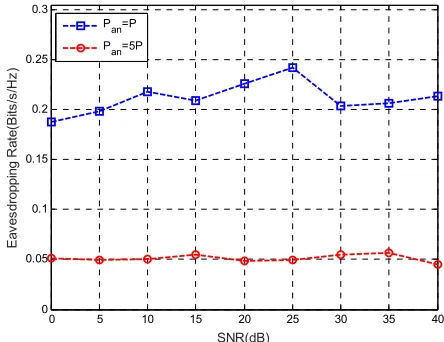
Fig. 5(a) shows the average transmission rate of the proposed scheme with different transmission powers of AN. From Fig. 5(a), one can see that the average transmission rates of legitimate user are almost same when Pan equals P or Pan equals
5P. Because the AN and the signal from the certain user-pair are independent, it makes the ZF of the AN separable. Thus, the ANs transmitted by receivers don’t affect the transmission rate. Also, from Fig. 5(b), one can see that the eavesdropping rate at the eavesdropper decreases when the transmission power of AN increases. It means that the secrecy performance can be actually improved by increasing the power of AN, while the average transmission rate of legitimate user can be maintained.
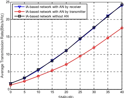
Fig. 6(a) shows the average transmission rate of three different schemes, where Pan=P. From Fig. 6(a), one sees that
the average transmission rate in the proposed scheme is the same as in the IA-based network without ANs. Both average transmission rates of the two schemes are larger than the
IA-based network with ANs transmitted by transmitters . The growth of the average transmission rate using the proposed scheme has not been influenced, because the AN and the signal are independent. In other words, the average transmission rate of the scheme using transmitter to transmit AN is affected by ZF, and thus is lower than the other two schemes.
Fig. 5. (a) Average transmission rate for different SNRs, when Pan=P or Pan=5P.
Fig. 5. (b) Eavesdropping rate for different SNRs, when Pan=P or Pan=5P.
The eavesdropping rate at the eavesdropper is presented in Fig. 6(b). For high SNR, one sees that the eavesdropping rate of the IA-based network without AN is close to 2bits/s/Hz, although it does not have the CSI between the eavesdropper and the receiver. In the IA-based network with AN transmitted by transmitter, its eavesdropping rate is about 0.8bits/s/Hz and higher than that of the proposed scheme. For the proposed scheme, because the eavesdropper does not know the CSI between the eavesdropper and the receiver, all the ANs can be used to disturb the eavesdropper. Therefore, its eavesdropping rate is less than 0.25bits/s/Hz.
It must be pointed out that the average transmission rate is the average value of all the user’s transmission rate, while the secrecy rate is defined as the difference between the transmission rate and the eavesdropping rate. If we are
0 5 10 15 20 25 30 35 40 0
5 10 15 20 25
SNR(dB)
A
ver
age
T
ra
ns
m
is
si
on
R
at
e(
B
its
/s
/H
z)
Pan=P Pan=5P
0 5 10 15 20 25 30 35 40 0
0.05 0.1 0.15 0.2 0.25 0.3
SNR(dB)
E
ave
sd
ro
pp
in
g
R
at
e(
B
its/
s/
H
z)
[image:10.612.51.298.112.306.2] [image:10.612.325.544.184.353.2] [image:10.612.320.542.379.550.2]concerned about the secrecy rate, combining Fig. 6(a) and Fig. 6(b), we can see that the secrecy rate in our proposed scheme is the highest. Thus, the proposed scheme is much securer than the other two.
Fig. 6. (a) Average transmission rate in the three different schemes.
Fig. 6. (b) Eavesdropping rate in the three different schemes.
Fig. 7. (a) Average harvested energy in the three different schemes
Fig. 7 shows the average harvested energy and transmission rate in the three different schemes. The X-axis is the power configuration weights for information transmission. In Fig. 7(a), the bigger harvested energy means the higher harvesting efficiency. For energy harvesting efficiency, due to the addition
of AN, the harvested energy is significantly higher than the IA-based network without AN. It can be predicted that the harvested energy performance can be already improved well in the proposed scheme with limited nodes, then the overall performance could be significantly improved if the proposed scheme is used in a large scale network. Regarding to the average transmission rate, one can see that the result in Fig. 7 (b) is similar to the result in Fig. 6 (a). The reason is the AN and the signal are independent in the proposed scheme, and hence the growth of the average transmission rate is similar to the scheme without AN and better than the scheme with AN transmitted by the transmitter.
Fig. 7. (b) Average transmission rate in the three different schemes.
Fig. 8. (a) Average transmission rate with and without relay cooperation.
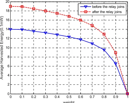
Fig. 8 represents the change of the average transmission rate and the eavesdropping rate in our proposed scheme, before and after the relay node joins. From Fig. 8(a), one can see that the average transmission rate is greatly improved after the relay node joins in the network. The higher the transmission power (i.e., the signal to noise ratio), the more obvious the superiority of the relay, and the more obvious the growth of the average transmission rate. In Fig. 8(b), whether or not the relay node joins in, the eavesdropping rate is similar in the two schemes. That is to say, the eavesdropper is unable to improve its performance using relay node, and is still jammed by the AN.
Fig. 9 shows the average transmission rate and harvested energy of the proposed schemes with relay and without relay cooperation. Along with the increase of the power configuration weights for information transmission, both the two average
0 5 10 15 20 25 30 35 40 0
5 10 15 20 25
SNR(dB)
A
ver
age
T
rans
m
is
si
on
R
at
e(
B
its
/s
/H
z)
IA-based network with AN by receiver IA-based network with AN by transmitter IA-based network without AN
0 5 10 15 20 25 30 35 40 0
0.5 1 1.5 2 2.5
SNR(dB)
E
ave
sd
ro
pp
in
g
R
at
e(
B
its/
s/
H
z)
IA-based network with AN by receiver IA-based network with AN by transmitter IA-based network without AN
0 0.1 0.2 0.3 0.4 0.5 0.6 0.7 0.8 0.9 1 0
2 4 6 8 10 12 14
weight
A
ver
age
H
ar
ves
te
d
E
ner
gy
(
0.
1m
W
)
IA-based network with AN by receiver IA-based network with AN by transmitter IA-based network without AN
0 0.1 0.2 0.3 0.4 0.5 0.6 0.7 0.8 0.9 1 0
2 4 6 8 10 12
weight
A
ver
age
T
ra
ns
m
is
sion
R
at
e(
B
its
/s
/H
z)
IA-based network with AN by receiver IA-based network with AN by transmitter IA-based network without AN
0 5 10 15 20 25 30 0
5 10 15 20 25 30
SNR(dB)
A
ver
age
T
rans
m
is
si
on
R
at
e(
B
its
/s
/H
z)
[image:11.612.61.276.104.275.2] [image:11.612.324.542.191.363.2] [image:11.612.59.276.298.470.2] [image:11.612.323.544.386.563.2] [image:11.612.60.274.495.669.2]