DATAMAX UV-1
Zgrass GRAPHICS SYSTEM
OPERATOR'S MANUAL June 1, 1982
Co !Jyr Igltt 1ge~ Red! Time DesIgn, lnc. 531 Plymouth CourL, SUIte 102
COPYRIGHT NOTICE
Copyrignt. 1982 by Real Time Deslt:?;n, Inc. All rit:?;llts reserved. No ~art of this publication may be reproduced, t. r d II S III it\.. ed, t [' a n S l! rib e u , S 1. 0 red i n a ret r i e val s y s t e!ll , o r lr'anslat.ed into any human or computer language, in any form ur by
3ny lIIedns: electronic, meeilallicdl, mdgnetic, opticc.l1, CIl(C:lIlic<.Jl, 1Il..iIIU.Jl, or ot.llerwise, wlthout tIle ex~ress writtell perlllissIuII u1'
l\~...il TIme DeSign, Inc., 531 Plymout.h court, Suite 102, CliIcdL,U, lL LiOGOS USA.
DISCLAIMER
l)atallldX, Inc. alld Hedl Tlme lJcslbll, inc. Illdkt: IIv l" C ~ I' e s e 1\ t c1 t I U 1\ S .) r w d r r d n 1. 1 e s w I til res ~ e c t t U ttl e cOli t to: II t S II ere U 1
dllCl spt:cif1Cdlly uisclaim ally 1mplieu wdrrdnties u1 llIeretldnt.abi 11 ty or 11 tness lor any part. icular purpuse. Fur' tller, DdtalllCix, Inc. and Reol Tillie Design, Inc. reserve tIle rlgllt tu l'evise tilis pUblication and t.o make cllanges from time to tilile ltl t.lle content hereof witnout obligation of Ddtamdx, Inc. <'HlU/vr heal T1me [)esibn, Ine. to tlotify any person or urgdtllzatlull u1' Suen reviSIon or cllanges.
****
Ref ere II c e s are III a d e til r 0 ugh 0 u t t hIS doc u men tat ion 1. a L11 e equipment. llsted below. We ilereby acknowledge use of ttlese names and/or trauemdrks 111 lllis publicatlon.
-ADr-1 5 Dumb 'iermilldl V1ueo Display Unlt
-Micropolis DISk Drive
-Bit Pad Une D~ta Tdblet/DigiLizer -Datamax WD-1
Mini-f'llnchester or ~FD-1 ~1nchester/ Floppy DISk Drive -E~son MX 60 PrInter
-CP/M (Control Program Monitor)
-Datamax RGB Mon1tor
Lear Slegler, Inc. Ddta Products Div. Analleim, CA
Micropolis Corporation Cc1nO!:!,d Pdrk, CA
Summdgrdpt1ics Corpordtion F<.Jiri'leld, CT
D a t d III a x, Inc.
Elk Grove Village, IL
E~son America, Inc. Torrance, CA
Digitcd Research P<.iclf1C Grove, CA Datarnax, Inc.
READ HE FIRSTl
This sheet identifies standard documentation included with the UV-1 Zgrass System. It is recommended that you review all standard documentation in the order listed below.
OPERATOR"S MANUAL
This manual instructs you on the set-up and testing of the computer and connection of peripheral devices. In addition, it provides you with important information about operating the system •.. such as, the hardware features and specifications; basic disk and audio tape management techniques; graphic considerations; etc.
THE Zgrass GLOSSARY
This glossary is the standard reference to the Zgrass language which defines and demonstrates Zgrass commands and terms. Sample programs are used to clearly demonstrate commands.
THE Zgrass LESSONS
This learning tool was designed to aid the interested novice in learning how to write Zgrass programs and create useful custom software.
PAINT PROGRAM USER'S GUIDE
This guide functions as both a step-by-step learning tool and a reference manual for the Paint Program ... to be used interactively in conjunction with the Paint Program disk provided with the system.
UTILITY DISK USER'S GUIDE
This guide is to be used in conjunction 'with the mul ti-purpose Utility Disk provided with the system (on the flip-side of the Paint Program disk). The Utility DiSK provides you with access to additional Zgrass commands (called SWAPS), additional fonts, Epson printer programs, and system test programs.
IMPORTANT NOTICE
SECTION 1. 1.1 1 .2 2. 2. 1 2.2 2·3
3.
3 . 1
3.2
3·3
3.4 3.5 3.6 4. 4. 1 4.2 4·3 4.4 4.5 4.6 5. 5.15 . 1 • 1
5.1.2 5.2 5.2.1
5·3 5·3.1
DATAMAX UV-l Zgrass GRAPHICS SYSTEM OPERATOR'S MANUAL
TABLE OF CONTENTS (QUICK REFERENCE)
TITLE
INTRODUCTION •
.
. . . .
.
.
. .
.
.
.
. .
.
.
.
Ttl e S y s t em. • • • • • • • • • • • • • • • • • •
The Operator's Manual & Supporting Documentation
HARDWARE FEATURES
.
. . .
.
. .
.
. . .
System Specifications . • . •• Front Panel Illustration . . . . • .
Front Panel Feature Detail . . . • . . • . . Rear Panel Illustration • . . . • . . . . .
Rear Panel Feature Detail . • • . • . . • .
INITIAL SET UP • •
. .
. . .
.
.
. . .
.
.
Careful Opening of Back Door . .
Removal of Foam Packing Material • . • . Unit Inspection . . . . • . . . • . . . RS232C Interface Baud Rate . . • . . . . Careful Replacement of Back Door . . . • • .
Connection of Peripheral Devices . . . . • . . •
SYSTEM POWER-UP
. . .
.
.
. .
.
. . .
.
.
.
PAGE 1 1 13
3 3i 4 4i 5 7 7 1 7 8 8 8 9Plug In Power Cord • . • • • • • • . . . . • 9 Power-On Terminal and Display Device . • • • 9
Power-On UV-l . • . . . • • • . . . • • • . 9
Verify System Power-Up . • . • • • . • • . • . . 9 System Test Animation • • • • • . • • • 10 What To Do If System Fails To Come Up • • • 11
UV-1 Zgrass GRAPHICS SYSTEM CONFIGURATION.
.
.
.
13SECTION
5. 5.4
5 .4 . 1
5.5 5.6
5·7
5.8
5·9
5.10 6. 6. 16.1.1
6. 1 .2
6·1.3 6 . 1 .4
TITLE
TABLE OF CONTENTS (QUICK REFERENCE)
UV-l Zgrass SYSTEM CONFIGURATION - Continued Mini floppy/Winchester Interface Board (Disk
PAGE
Drive Cable Connection). . . 18 ATTENTION: Allow S~ace for Board Enhancement. 18 Memory Board 2 (EPROMs for Software Updates) 18 Additional Boards
Multi-Page RAM Board . CPU Board . . . .
Console Lights . • . . . . Console Switches • • . . . . Using Ports . . • . . . . . 3-Voice Sound Synthesizer . . . PERIPHERAL DEVICE CONFIGURATION
Data Interfaces and Peripheral Devices
Terminal . . . . . . . . . -Terminal Preparation . . . . . . -Cable Connections . • . . . . -Cable Specifications - Illustration
Tablet . . . .
-Tablet Preparation . . . . . . -Cable Connection . . • . . . ' . '
-Cable Specifications - Illustration . . . . Handcontrols (Joysticks) .
Disk Storage . . . . . . . . -Disk Drive Preparation . . . . -Cable Connection . . • . . . . -Cable SpeCifications - Illustration -Floppy Disk Management . . . .
--Disk Description • • • . . . --Handling Instructions (Load/Unload)
--Write Protection . • . . . --Care of Disks . • . . . . --Formatting . . . . . . .
--Initialization . • . . --Disk Cache . . . .
-Hard Disk Management . .
20 20 20 20 21 21 22 24 24 25 25 26 26i 27 27 28 28 i
SECTION 6. 6.1.5 6.2 6.2.1 6.2.2 6.2.3 6.2.4 7. 8. TITLE
TABLE OF CONTENTS (QUICK REFERENCE)
PERIPHERAL DEVICE CONFIGURATION - Continued
PAGE
Audiotape Storage • • • • • • • • • • • • 36 -Tape Recorder Preparation. • • • • • • • •• 36 --Recorder Configurations - Illustrations 36 --Recorder Tuning • • • • • • . • • •• 37 -Cable Connections •• • • • • • 38 -Tape 1/0 • • • • • • • • • • • • • • • • • • 38 --Record (Output) • • • . . • • . • • • • • 38 --Play (Input) • • • • • • • • • 39 --1/0 Tips • •• • • • . • . . . . • 40 Video Interfaces and Display Devices •
NTSC Composite Video and Audio Out • -Device Preparation • • • • • • • • . -Cable Connection (Video and Audio) .
RF • • • • • • • • •
· . .
-Device Preparation •.
.
.
· . .
.
-Cable Connection • •
. . . ·
.
. .
.
.
.
. .
R-Y,B-Y,Y To RGB •• -Device Preparation • -Cable Connection •
· . .
.
.
.
.
. .
.
. . .
.
.
· .
.
. .
. .
. .
Display Considerations • . • • • • • •
·
. .
.
-Center of the' Screen • • •. .
-Aspect Ratio . . • • • • • • • •· .
-Colormap • • • • . • .· .
.
. . . .
TROUBLESHOOTING
. . .
.
.
. .
. .
. . .
.
1.1 The System
DATAHAX UV-1
Zgra,s GRAPHICS SYSTEM OPERATOR'S MANUAL1. INTRODUCTION
The Datamax UV-l Zgrass GraphIcs Syst~m is a Iligtll y interactive, dedicated micro computer color graphics system designed to easily produce visuals in motion. The UV-l (University VersIon 1) hardware is Z80 microprocessor-based. TIle 19rass (l80-GRAphics Symbiosis System) software is uottl a l1igh leve 1 computer- gr aphlcs lciOguage and a so ph is t iCated op~r e:l\. inl5 system. Th~ EPROM (Eraseable Programmable Read Only M~mury)
firmware houses Zgrass and allows-for easy software updates. The system's heritage derives from video arcade games, and the high-speed animation "tricks" so easily programmed on this computer are a result of the development of video game technology and custom video chips.
1.2 The Operator's Manual
&
Support1na DocumentationThe Datamax UV-l Z rass Gra hics S stem 0 erator's has been deSigned to unction not only as a guiae for set up of the system, but also as a reference manual during routine operation of the syste~.
Manual initial
useful
The TABLE OF CONTENTS doubles as a QUICK REFERENCE section, listing all section. headings. Detailed instructions, descriptions, and appropriate illustrations are presented in the body of the manual to guide the user. The TROUBLESHOOTING section provides tips for solving problems. The INDEX OF SYSTEM TESTS locates all the testing programs (macros) contained within the body of the manual and explains how to use the UTILITY DISK to load and run these tests.
References are maae throughout this manual to the following additional supporting documentation of tile system:
The Datamax UV-1 Zgrass Lessons - !tIe lessons wt:re deslt~ned
to aid the interested novice in learning how to control the system and create uset'ul custom software.
The Datamax UV-1 Zgrass Glossary - The glossary defines and demonstrates commands and terms necessary for the use of the Zgrass language.
DATAMAX UV-1 Zgrass GRAPHICS SYSTEM
2. HARDWARE FEATURES
2.1 System Specifications
o Zgrass firmware: 32K EPROM
o 32K user RAM expandable to 64K for CP/M compatibility o 256K screen RAM; 16 screen pages of 16K bytes each, 12
of which may also be used for solid st~te disk cache o 256 possible colors, 4 colors per pixel (victure element) o 320 x 201 x 2 bit resolution
o Z80 microprocessor
o custom I/O (Input/Output) processor o custom video processor
o Arithmetic Processing Unit o 3-voice sound synthesizer
o 1800 baud audio t~pe interface ,
o Two DC motor controllers (reed relay closure for cassette tape units)
o Two RS232C ports .
o capability for Micropolis 1033-1V 5.1/4" flOPPY disk drive and IMl Winchester-type hard disk drive
o interface for graphics tablet
o front panel connections for headphones, light pen, and 4 handcontrols (joysticks)
o ~nti-static, formica-woodgrain cabinet
o NTSC composite video output, channel 3 or 4 RF output, and R-Y,B-Y,Y output
HARDWARE FEATURES
FRONT PANEL
CD
CONSOLE LIGHTS..•..
..,utli®
CONSOLE SWITCHESoooo.()ooo
0 0 0 0 0 0 0 0 0 0 0 0 0 0 0 0 0 0 0 0 0 0 0 0 0 0 0 0 0 0 0 0 0 0 0 0 0 0 0 0
@
SPEAKERCD
LIGHT PEN JACK®
VOLUMe CONTROL KNOB@
RESTART SWITCHIi • • '~'--;'t
\ . , I I ""---""'"
~I •••• I
"---'
•
POWER INDICATOR LIGHT
2.
HARDWARE FEATURES - Continued2.2 Front Panel Feature Detail
1) CONSOLE LIGHTS jJrogrammable on
Glossary).
(16) - Assigned numbers
2 different output ports
2) CONSOLE SWITCHES jJrogrdmmClble on 2
Glossar'y) .
(16) - Assigned
uifferent input.
numbers
JJOrl .. s
0-1'J,
user-(see PORT in
0-15,
user-(see PORT ill
3) RESTART SWITCH (RST - leftmost ot" 2 red switches) - Same as RESTART command: clears user memory (RAM), and resets system
to default colors it'
"Y"
is typed in response to jJromjJt onterminal. In the event of accidental restart,
"N"
resjJonseavoids the clearing of user memory.
4) BREAK SWITCH (BRK - rightmost of 2 red switches) - Same as RESTART SWITCH except that colors are not reset; same
prompts and responses on terminal.
5)
HEADPHONE OUT (1/4" phone jack) - Monaural,8
ohms lmpedance,cuts out speaker, volume controlled by volume control dial;
monitors audio output of 3-voice synthesizer accessed via
PORT command (see Glossary).
6) VOLUME CONTROL KNOB - Controls audio output gain of headphone
output and speaker.
1) LIGHT PEN JACK - Light jJen option not supported at this time.
8) SPEAKER - Monitors audio output of 3-voice synthesizer
accessed via PORT command (see Glossary). Speaker volume
controlled by volume control dial; speaker disabled when
headphone output is used.
9) JOYSTICK JACKS (four DB 9S joystick sockets) - Accessed as
user-programmable device variables (see JOYSTICK and DEVICE
VARIABLES in Glossary).
G)
LINE AUDIO OUT®
RFOUTHARDWARE FEATURES REAR PANEL
@
NTSC COMPOSITE VIDEO OUT@)
0
AUDIO II'
•• T "AD
e
VIDEO
ACCtSSO" •
o
R-Y.B-Y.Y VIDEO OUTTt"""IAL
[§
TA~I ~
(£-.!.0
•• OUT OUT
®
®
TERMINAL RS232C CONNECTOR(J)
ACCESSORY RS232CCONNECTOR
®
BIT PAD CONNECTOR®
FUSEOff
0"
2. HARDWARE FEATURES - Continued
2.3 Rear Panel Feature Detail
1) LINE AUDIO OUT (RCA phono connector) - Approximately 1 volt P-P, "200 ohms impedance or higher. Output audio from 3-voice synthesizer, accessed via PORT command (see Glossary).
2) RF OUT
("F"
connector) - Outputs RF video to antenna input on standard TV receiver on VHF channel 3 or 4, home videocassette recorder, etc.3) NTSC COMPOSITE VIDEO OUT (BNC connector) - RS 110; 1 volt P-P, 15 ohms impedance. Outputs composite, NTSC standard video to video monitor, videotape recorder, switcher, etc. Contact Datamax for future availability of GENLOCK option.
4) R-Y,Y,Y VIDEO OUT (Mate'n'Lock connector) - Outputs R-Y, B-Y, Y video to Datamax RGB monitor which contains RGB convertor board (also available from Datamax). Contact Datamax for future availability of direct RGB board.
5) FUSE - MDA-1.5 amp.
6) BIT PAD (DB 25S connector) - Parallel interface currently compatible with Summagraphics Bit Pad One. Any other tablet uses accessory RS232C interface with user-developed software.
1) ACCESSORY RS232C (DB 25S connector) - Serial interface to connect disk drive, printer, plotter, modem, additional computer, etc. See BAUD RATE section of this manual for instructions on setting baud rate - also see RS232 in Glossary.
2. HARDwARE FEATURES - Continued 2.2 Rear Panel Feature Detail - (Continued)
9) TAPE INTERFACE (two 1/8" m1nl \-JtlOne joCkS dnd two suD-mllll \-Jllone jacKS) - t-lln1 JdckS for aUd10 dCita IN/GUT dnJ {JUT dt 1,800 baud rate and sub-mini JdckS for remote motor trlbber of DC Slbnclls. The motor controllers (reea reldY closure::; rdted at 1/2-Qm~, 100 volt DC, 500 ol'lms contdct resistance) Cdn be used to tr1bger other deVices, SUCll as film camerdS, time lapse videotape recorders, etc. See PORT in Glossdry tor direct program control uf motor sW1tch. See hUDIGThPE STORAGE Sect10n 6.1.5 of tnis trJdnucd lor cunnections dn.] proceuures.
10) AC IN (3-prong plug) - AC, 120V, 60 HZ, 150 ~ATTS ~jAX
11) AC OUT (UNSWITCHED) (3-prong socket) - Unswltctlea he power for peripherals. NOTE: Per1phercHs drawing AC tnrougn the UV-l raise tne lin~ protectloo requirement.
3. INITIAL SET UP
Before configuring your UV-1 Zgrass Graphics System, consider your working environment. To avoid overheating the unit, set it up in a cool room. Always allow enough open space around the unit for adequate ventilation. Air is taken in from beneath the unit, then forced out through the back door by the fan. Be sure that paper is not allowed to get under the unit where it might be sucked up against the bottom and block airflow. If you wish to reduce the possibility of static electricity interference, place an anti-static mat under your chair.
Carefully remove the unit and its power cord from the packing box. Locate ttle key taped to the back door and insert the key into the back door lock. BEFORE YOU PLUG IT INTO AC POWER, take time to inspect the unit as follows:
3.1 Careful Opening of Back Door
Set the unit on a flat surface on its feet. Because the fan attached to the back door is connected to the power source by wires, care must be taken in removing the back door without pulling the fan wires. Unlock the back door and grasp the key to tilt the panel out and down until there is enough clearance to grasp the edge of the panel; lift the panel up and away from the unit just enoug~ to dislodge the tongue at the base of the panel from the groove of the cabinet floor. Unlock the Mate'n'Lock connector by pressing do~n on the tabs and pulling the connectors apart to release the fan wires from the AC power source. The door may now be removed from the unit.
WARNINGI Extreme car-e must be exercised in handling internal system hardware components. Printed circuit (PC) boards can be damaged by improper handling, causing the unit to malfunction. Handling of internal hardware components is advised only when absolutely necessary.
3.2 Removal of Foam Packing Material
Once the back door is open, remove all foam packing material that may be wedged just inside the back door opening.
3.3 Unit Inspection
3. INITIAL SET UP - Continued
3.4 RS232C Interface Baud Rate (terminal and accessory)
With the unit still unplugged from AC power, set the intertace baud rates according to your terminal and accessory requirements. See BAUD RATE SELECTION Sect.ion 5.3.1 ot' LhlS manual for procedures.
3.5 Careful Replacement of Back Door
Reposition the back door and reconnect the fan, you push the wires clear of the fan blades as you back door.
3.6
Connection of Peripheral Devicesmaklng sure replace ttle
See PERIPHERAL DEVICE CONFIGUkATION Section 6 in this manual for instructions on mdking appropriate connections between the UV-l, the terminal, video display aevice, etc., and then proceed Wltn SYSTEM POWER-UP Section 4.
UU-l CRRO RRCI( BURROS
A
I
I
(- 1"-0 LOGIC
~
34
pin
26
pin
(- extra
slot
~~~~~~--~~~----~
~i"
(-
DISK
o
~
(- MEMORY
U
(-
SCREEN
I
I ( -
CPU
v
CI
o
0
C-...-~)
(
)
This image was using the
4. SYSTEM POWER-UP 4.1 Plug In Power Cord
With the power switch on the rear panel OFF, plug the power cord supplied with the unit into the AC IN jack on the rear panel. Plug the power cord into ~ 3-wire AC grounded outlet supplying 120-V at 60 HZ with nomin~l 15 amp.
4.2 Power-On Terminal and Display Device
POWER-ON your terminal and display device (video or Dat~max
RG8 mon i tor or TV). When the ADM 5 termi nal is powered on, the red light of the CAP LOCK key on tlie keybo~rd is usually lit. Press it to turn the light off.
4.3 Power-On UV-1
When the terminal and display devices ~re warmed up (about 5-10 seconds), POWER-ON the UV-l. NOTE: If you hear a clicking noise coming from the UV-l, turn the unit off, unplug the power cord, and open the back door to push the fan wires ~way from the fan blades and return to the instructions in Section 4.1. At system start-up, always verify that the fan at the rear of the unit is blowing air out of the unit. If there is no air flow, turn the unit off and see TROUBLESHOOTING Section 7 of this manual.
4.4 Verify System Power-Up
When the UV-1 is powered-up, the red ~ower indicator will light up on the front panel. The display device will display a white screen and the terminal will flash this message:
Copyright 1982 Real Time Design, Inc. All Rights Reserved
This is the official copyright notice of the Zgrass software residing in the EPROM firmware. The terminal will clear and then display:
Zgrass V*.*
.. C
>
4. SYSTEM POWER-UP - Continued
Press the HST .switch on the UV-1 front panel. The console llghts will bllnk cHI(J ttle terminal wlil prompt you Wlttl:
ERASE ALL? (Y OR N)
respond by pressing the Y key. This erases or clears all 01' user memory.
4.5 SYSTEM TEST 1: GRAPHICS
To run a system test animatlon called NICE BOXES, type: NB
Press the RETURN key. An animated ~isplay of colored boxes wlll appear on the display device; when the test has been completea, the Zgrass
>
prompt will appear on the terminal.NOTE: Follow all typed commands on the terminal by pressing the RETURN key.
If you type:
NB
again, the boxes will erase themselves and clear the screen.
SYSTEM TEST 2: SCREENS Now type:
NC
Press the RETURN key and a 16-screen animation of clrcles and squares will be drawn on the display devlce. When this test has cycled a few times, interrupt lt by tiolding down the CONTROL key
while pressing the C key. Throughout system documentation, ttllS
process of haltlng a program is referred to as CTRL.C or simply "'C.
To complete this test, you must reset the screens and default colors by pressing CTRL.B:
4. SYSTEM POWER-UP - Continued
SYSTEM TEST 2: SCREENS - Continued To clear the screen, type:
CLEAR
Then, press RETURN. If the system displHYs the tests as described above, the system hHS been successfully powered up.
4.6 What To Do If System Fails To Come Up
5. UV-1 Zgrass SYSTEM CONFIGURATION
This section provides an overview of the UV-l, including the hardware, baud rate selection, and the use of the hardware ports.
5.1 Handling Hardware
Occasionally, it may be necessary for you to handle the main printed circuit (PC) boards contained in the card rack. For instance, to change baud rate settings of the RS232C ports, you must access the I/O Logic Board; to make a software update by changing the EPROMS, you must access the Memory Board 2.
5.1.1 WARNINGI Extreme care must be exercised in handling internal system hardware components. PC boards can be damaged by improper handling, such as fingerprinting the gold plating on edge connectors, exposing the board to static electricity, or unduly flexing the board. Handling of internal hardware components is advised only when absolutely necessary.
If it is necessary for you to access an internal hardware component, remember:
5.1.2 TURN THE UNIT OFF and disconnect all power cords. NOTE: Even when the unit is turned off, if the pow~r cord is plugged in, there will be 120 volts of power inside the chassis.
See Careful instructions on components.
5.2 Card Rack
Opening of Back Door opening the unit to access
Section
internal 3.1 hardware for
slotted mounting device designed to contain up It is mounted on the front wall, with its This is the
to 6 PC boards. opening facing accessing and illustrations board.)
the back door of the unit. Instructions for re-inserting PC boards follow. (Refer to board for highlighted information relating to each
5.2.1 Accessing and Re-Inserting PC Boards in the Card Rack
5.
UV-1 Zgrass SYSTEM CONFIGURATION - Continued5.2.1 Accessing and Re-Insertlng PC Boards - Continued
In Lhe event you find it necessary to completely remove a board from the card cage, you must disconnect the 40-pin ribbon cable connecting the 1/0 Logic Board to the back panel board. Instructions for dOlng so are contained ln Section 5.5 (Memory BOard 2).
TO RE-INSERT a bOard, carefully orient and re-connect any cables disconnected to access the boaro. If it has been necessary to fully remove the board from the racK, align it in the proper slot of the rack, component side up, being sure to insert ttle board into the metal tracks on ei ther side of the card rdck, and then re-connect allY cables disconnected to access the board. Apply firm pressure to the card ejectors and push the board straight back lnto tHe card rack until all boaras line up. You'll notice a little resistance in seating the edge of the board in the socket at the far end of the card racK. Gently rocking the board by applying pressure f'irst to one card ejector and then to the other will help properly seat the board.
Hemember to reconnect the ribbon cable from the 1/0 Logic Board to the back panel board if you disconnected it. BE SURE TO CHECK THIS CONNECTION! Both rows of pins must be connected and no pins should be exposed on either side of the connector. If there is no response on the terminal after system power-up, turn off the unit, unplug the power cord, and check this connection.
5.
UV-1 Zgrass SYSTEM CONFIGURATION - Continued5.3 I/O Logic Board (Baud Rate Switch)
This board is the interface between the microprocessor anu the peripheral world. The DIP switch for setting baud rates of the two'RS232C hardware ~orts is located on this board. This board is distinguished by the cables connected to the top of the board near the exposed edge. The leftmost connection is a 50-pin ribbon cable leading to the front panel. The middle connection is a 40-pin ribbon cable leadjng to the rear panel. The rightmost connection is a bundled cable liarness leading to the Video Board located on the floor of the unit.
VERIFY THAT AC IN POWER IS UNPLUGGED BEFORE PROCEEDINGII
To access the DIP switch on the 1/0 Logic Board, carefully remove the 50-pin cable (the leftmost cable) by grasping the cable connector and gently pulling strdight up. Gentle prying ,with a small screw driver will help lift the cable connector t'rom its mating connector which is soldered to the board. DO NOT pull directly on the ribbon cable as .this may separate it from its connector.
BAUD
RATE
DIP
SWITCH
I/O LOGIC BOARD - ILLUSTRATION
190 pin edge connector
u u
u
u
U
I U
U U
D
D
U
D
A
I
...
...
:l ~
o
n
'1
.,
0-.,
'1
~
____________
~lr~__________
~1 I~__
~,~n
~~~~---
____________
-Z~~A5. UV-1 Zgrass SYSTEM CONfIGURATION - Continued 5.3.1 Baud Rate Select ion
To enable the UV-1 19r~ss Graphlcs System to communicate lJroperly with such peripher~ls as a terminal, printer, plotter, modem, etc., you must set the eight b~ud r~te selector switches located on the I/O Logic Board DIP switcll as specified for each perilJheral. The factory pre-sets the baud rate selector switches for the terminal to 19200 and the ~ccessory port to 600. If these settings are aPlJropriate for your devices, there is no need to re-set the baud r~tes or to remove this board.
VERIFY THAT AC IN POWER IS UNPLUGGED BEfORE PROCEEDINGII
See Section 3.1 (Careful Opening of Back Door) for instructlons on opening back door of the UV-1 unit ana Sectlon
5.3 (1/0 Logic Bo~rd) illustration for location of the DIP switctl on the I/O Logic Board. Spread the card ejectors ~nd gently pull the board out-of the rack far enough to disconnect the leftmost rlbbon cable connector (be careful not to bend any pins!). Pull the board out just far enough to access the baud rate selector switches on the DIP switch which look liKe ttlis:
BAUD RATE SELECTOR SWITCHES ON THE I/O LOGIC BOARD DIP SWITCH
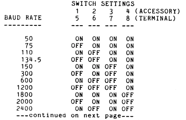
The bank of switches containing switches 1-4 controls the RS232C accessory interface; the bank containing switches 5-8 controls the terminal interface. The following table lists the switch settings for b~ud rates ranging from 50 to 19200. The setting for a specific baud rate is the same for either terminal or accessory, just set the proper b~nK of switches.
SWITCH SETTINGS
1 2 3 4 (ACCESSORY) BAUD RATE 5 6 7 8 (TERMINAL)
---50 ON ON ON ON
[image:29.611.198.516.521.726.2]p~ge---5.
UV-1
Zgrass SYSTEM CONFIGURATION - Continued5.3.1 Baud Rate Selection - Continued
SWITCH SETTINGS
1 2 3 4 (ACCESSORY)
BAUD RATE 5 6 1 8 (TERMINAL)
---3600 OFF OFF ON OFf'
4800 ON ON OFF OFF
1200 OFF ON OFF OFF
9600 ON OFF OFF OFF
19200 OFF OFF OFF OFF
The recommended baud rate for the terminal is 19200,
although 9600 is acceptable. The higher the baua rate, the faster data is transferred between the
UV-1
and the terminal. Baud rates for accessories vary depending on device requirements. For example, the Epson printer with 2K buffer can receive data at several baud rates, including 600 or 1200 baud; a modem may transfer data at 300 baud. Th~ factory setting for the DIP sw itch on the 1/0 Logic Board is ill ustrated below:•
EXAMPLEBAUD RATE DIP SWITCH SETTINGS
1 2 3 4 5 6 1 8
ION ION
,
ON I
I I I I I I I I I I I I I I I I I I
OFF 10FFIOFFI 10FFIOFFIOFFIOFFI ACCESSORY TERMINAL
600 19200
When you nave completed setting the baud rate switches to the baud rate specifications'required by your equipment, reconnect the leftmost ribbon cable and carefully slide the 1/0
Logic Board into its slot in the card rack. If you meet resistance, gently rock the board from side to side until it slips in--DO NOT FORCE ITI Close up the back of the unit (per Section 3.5) and re-plug the AC IN to a power source.
Before going further, verify that the baud rates on the terminal and accessory device are set as specified by their documentation and that those rates agree with the rates you've
just set on the 1/0 Logic Board DIP switch.
5. UV-1 Zgrass SYSTEM CONFIGURATION - Continued
5.4 Mini floppy/Winchester Interface Board (Disk Drive Cable Connection)
Refer to the UV-1 Card Rack boards Illustration in 3.6 Connect.ion of Peripherctl Devices for illustratIon board edge connectors.
Section of DISk
VERIfY THAT AC IN POWER IS UNPLUGGED BEfORE PROCEEDINGII
This board connects the Micropolis and Winchester disk drives to the system. The cables connecting your disk drives to the UV-1 are connected to the exposed edge of this board, as follows:
LooKing from the back of the unit, the leftmost ana wider ot' the two edge connectors accommodates the 34-pin cable used to connect a Micropolis disk drive. Pin 1 is located on the top right side of tile connector, with Pin 33 on the top left. The rightmost and narrower connector accommodates the 26-pin cable used to connect a Winchester disk drive to the system. Pin 1 is on the top right side with Pin 25 on the top left. Refer to UV-1 Card Hack Boards illustration for location of 34-pin and 26-pin edge connectors on disk drive board.
5.4 . 1 ATTENTION: Allow space for board enhancement.
Boards numbered A084-91542-A948 should have a piggyoack data separator board for increased reliability. Boards numbered A084-91542-B948 have the circuitry included and should not have the
piggyback ooard. The piggyback board is directly attached to the top of the disk board. This means two slots of the card rack are required to accommodate this configuration. Upon cursory inspection, the slot above the disk board may appear to be empty; however, closer inspection will reveal that the upper slot is actually occupied by the piggyback board. Accordingly, do not insert another board in the slot directly above a disk drive board without taking the piggyback space requirement into account.
5.5 Memory Board 2 (EPROMs for Software Updates)
5.
UV-l Zgrass SYSTEM CO.FIGURATION - Continued5.5 Memory Board 2 - Continued
The EPROMs are numbered from 1 to 8 corresponding to the numbers printed on Memory Board 2 next to each socket. The EPROMs ~lso have a notch on one end which must line up with the notch printed on Memory Board 2. Inserting EPROMs incorrectly can damage them and cause a software failure necessitating EPROM replacement.
VERIFY THAT AC IN POWER IS UIPLUGGED BEFORE PHOCEEDINGII
In order to extract Memory Board 2 for an EPROM update, first disconnect the 40-pin ribbon cable connecting the 1/0 Logic Board to the back panel board which blocks the removal of Memory Board 2. Grasp the cable connector where it connects the back panel board and gently pull straight up. DO NOT pull directly on the ribbon cable as this may separate it from its connector. It' necessary, gently pry the connector with a small screw driver, being careful not to bend the pins.
MEMORY BOARD 2 - ILLUSTRATION
199
pin
edge connector
DOD
000
000
o
0
This image was generated on the UV-l system using the Zgrass Paint Program.
A I
....
....
:s
c+
o
n
Q
"'S
Q."'S
Q
n
5.
UV-l Zgrass SYSTEM CONFIGURATION - Continued 5.6 Additional BoardsAlthough additional boards are mounted ln the c~ra cage, there Should not be any need to access these boaras.
-Multi-Page RAM Board
This board contains 256K bytes of screen RAM (16 pages of screen memory, 16K bytes each). DO NOT alter the settlng 01"
the trim pot on this board. -CPU Board
HilS board houses the Z80 CPU (microprocessor), system clocks, and custom address and dat~ chips.
5.7 Console Lights
These are the 16 LED's (Light Emlttlng Diodes) numbered 0-15 on tne front panel. Functionally,-these llgnts are divided into two banks (0-7 and 8-15), each bank considered a "port" software-access i bl e by the PORT command. These Jirogr alOmabl e lights prov ide feedback about the status of system processes. For instance, after pressing the RST or BRK switch, the blinking of the lights indicates that the system is looping through a process requlring input to end the lOOp. These lights also provide feedback during some commands which take a long time to execute. By watching the sequential blinking of the lights during disk operatlons, you can determine which sector of the disk is currently being DINITialized, DLOADed, OR DCOPY'd. See USING
PORTS, Section 5.9 for details on evaluating and converting binary console light values to ~ecimal values.
Console lights are set and cleared by the PORT command. Port 38 references lights 0-7 ana port 39 references lights 8-15. See PORT in tne Glossary.
SYSTEM TEST
3:
LED'S/SWITCHESType in this test to lock console switcnes to LED's so that toggling a switch turns the light above it on/off:
TEST3=[ .System Test 3: LED's/Switches PORT 38,POR! 20
PORT 39,PORT 21 SK -2]
TEST3
By locking the console switch ports to the console ports, the output of the switch ports lS the input of the ports, turning them on and off.
To interrupt tnis test, press CTRL+C.
5.
UV-l Zgrass SYSTEM CONFIGURATION - Continued 5.8 Console SwitchesThese are the 16 switches also numbered 0-15 on the front panel beneClth the LED's. L ike the console lights, these sw i tctles are functionally divided into two banks or ports (0-7 and 8-15) accessibie via the PORT command. These switches may be programmed as input devices, program signals, user-progrdmmdble interrupts, signals to cClll utility programs, etc.
Console switches are set and cleared by throwing the switches as follows: SET a switch by preSSing its lower rocker, throwing its upper rocker out; CLEAH a switch by pressing its upper rocker and throwing its lower rocker out. The status of a console switch may be determined by invoking the PORT command to read its status. Port 20 reads switches 0-7 and Port 21 reads switches 8-15. See POHT in the Glossary. See USING POHTS, Section 5.9 for information on evaluating the binary value of a switch.
If you did not try SYSTEM TEST
3:
LED'S/SWITCHES while in ~he Console Lights Section 5.7, do so now.5.9 Using Ports
Ports are addresses for system input and output which give you direct access to internal and external devices. Ports for the 3-voice synthesizer Clnd console lights are "writeable", which means you can alter the port values by using the PORT command. Other ports, such as those used for console switches or joysticks, are "readable", WhiCh means that when a switch is toggled, the value associated with that port is changed and can be read by using the PORT command. Another type of port, such as the RS232 port, is a "read/write" port. See PORTS in the
Glossary. ..
References to port numbers are in decimal notation (base 10), whereas the value of each port is stored internally in binary (base 2). Each port holds 1 byte of data composed of 8 bits. Each bit can have a value of either 0 or 1, referred to as cleared or set. Since each of the 8 bits have 2 possible states, byte has a potential decimal value range from 0 (if all bits are cleared) to 255 (if all bits are set).
Certain devices require 2 ports. For instance, since there are 16 LED's (console lights), each of which can be set (lit) or cleared (unlit), 2 ports are needed to store the values. The same is true for the console switches. One port handles the low order byte (bits 0-7) and the other port handles the high order byte (bits 8-15).
Each bit has a value relative to its position in the byte.
5. INTERNAL SYSTEM CONFIGURATION - Continued
5.9 Using Ports
-
ContinuedThe fa llow ing illustration gives the bit values for each position:
DECIMAL VALUE
->
128 64 32 16 8 4 2BIT OR I 1 =SET
I
BINARY VALUE
->:
0 0 0 0 1 O=CLEARLOW ORDEH BYTE: 7 6 5 4 3 2 1 0 <-BIT II
HIGH ORDER HYTE: 15 14 13 12 11 10 9 8 <-BIT II
This byte has a binary value of 00001111 and a decimal value of 8+4+2+1 or 15.
Re-type SYSTEM TEST 3: LED'S/SWITCHES provided in the Console Lights Section 5.7. Turn all LED's off by depressing the upper rockers of the console switches; then turn LED's 3, 2, 1 I
~nd 0 on by depressing the lower rockers of switches 3,2, 1, and
a
in. By turning switches 0-3 on, you have loaded decimal values 8+4+2+1 into port 38. This port displays the binary value 00001111 for LED's 7-0.Some ports share bits in their byte with other ports. ports 20, 21, 22, and 23 are examples of shared ports. (See 3-Voice Sound Synthesizer Section 5.10.) For instance, Port 22 controls two voices ••. the lower four bits for VOice A amplitude and the upper four bits for Voice B amplitude. By setting Port 22, Voice A can have a value ranging from 0 to 15 (O=low; 15=high). Voice B can also have a value· from 0 to 15, but this value must be shifted to the upper bits by multiplying the value by 16. To load both values into Port 22, add (value of A) to «value of B)*16» :
Port 22=(0 to 15)*16+(0 to 15) Voice
B
Voice A See PORT in the Glossary.5.10 3-Voice Sound Synthesizer
Please refer to USING PORTS Section
5.9
before proceeding with this section.5. UV-l Zgrass SYSTEM CONFIGURATION - Continued
Master Oscillator (a programmable frequency divider) is input to the three tone oscillators: Voice A, Voice 13, Clnd Voice C. Thus, changes made to the Master Oscillator at'fect all three voices.
MASTER F~EQUENCY FORMULA:
Master Oscillator frequency = 1189 Khz/(value of (PORT 16)+1) VOICE FREQUENCY FORMULA:
PORT 16 1'7 18 19 20 21 22
23
Voice frequency = 894 Khz/«PORT 16)+1)*«voice POHT)+l) (refer to the following table for voice PORTs)
VALUE RANGE 0-255 0-255 0-255 0-255 0-63 +[0,64,128,192] 0-15 +[0,16] +[0,32] 0-15 +(0-15)*16 0-15 +(0-15)*16 ORDER: LOW-HIGH 255-0 255-0 255-0 255-0 0-63
o ..
1920-15
o ..
16o ..
320-15 0-255 0-15 0-255
DESCRIPTION
Master Oscillator frequency
Voice A division ratio to compute tone Voice
B
division ratio to compute tone Voice C division ratio to compute tone Amplitude of vibrato modulationof Master Oscillator
Frequency of vibrato modulation of Master Oscillator
VOice C amplitude
Switch: vibrato (0) or Noise (16) to modulate Master Oscillator Switch: noise added to finCil
output; NO (0) or YES (32) VOice A amplitude
VOice B amplitude
Amplitucte of noise. to modulate Master Oscillator
Amplitude of noise added to final output
NOTE: Ports 20 through 23 are shared ports, as indicated in Section 5.9 USING PORTS. SYSTEM TEST 4: SOUND
Please refer to Section 8 INDEX OF SYSTEM TESTS for System Test 4: Sound.
N
I.N
....
Interactive Computer Graphics Facility
Video Camera
Film Chain
q ...
~
000 000
o
••
000 000: Dlgltallmage
o ••
~
• Processoro i •
".'.1120
~
301II
I
~.
•••••••
•••••••••00;
0,,.
...
·I,II~J-n
· [§]
Taper
Ii61
: B
~
VTR . .l'
0 '•
,00
J)~-)
•
I~)
·
.· I·
•
•
•
•
I·
•
•
•
•
•
•
•
•
...
'.
000 0 0 0 000
: · · · ' 0 0 0 0 0 0 000
•
•
•
•••••••••••••...
:
•
•
•
•••••••••••••••
I~
Q
Jl~.~
Joystick
~
• • • •••••••••••••
III'-'Il
•
•
•
•
~
~~
10 0 0 ;
0001 0 I • • • •
0001 !
Funcllon SWitches ~~ 0
and Dials
o
•
•
•
•
•
•
•
•••••
=
roo 0 0 OU;;I'
La. O~ O,QOE.,
RGB Mon,tor or Color TV
Line Pnnter
Plotter
Turtle tor Roboll
Optical Pnnter
A",matton Stand
!,
"'tom,;
Sound SyntheSizer Input•••••
Output Terminal
...
~
6.
PERIPHERAL DEVICE CONFIGURATION
6.1 Data Interfaces and Peripheral Devioes
Many of the features which make the UV-1 Zgrass SYSTEM a powerful tool are those which support interfacing with other data and video devices.
GRAPHICS
flexible Some of these features ~re: programmability of DC sign~l controller ~nd console switches, the 3-voice sound synthesizer, hardware interf~ces for termin~l, disk drives, prlnters, ~nd plotters, and software for interactive controls such ~s
h~ndcontrols and a t~blet. The diagram on the opposite p~ge
6. PERIPHERAL DEVICE CONFIGURATION - Continued 6.1.1 Terminal
Ttl e t e r min cd use d WItt I L Ii e U V - 1 rn u s t h d V e b 0 trl U ~ tJ e r d n CJ
lower cCise character capability. In Zgrass, Benercd mode IS up~er Cdse, WIth lower case being used only for loc~l v~riCiDles. ThIS rnecHIS that.. tne ZgrClss ectlo IS ttle reverse of ttle up{.Ier/lower cdse tunctions ot' your tt::rminCil .•. so thCiL, when you tYPt:: s (> III e t h HI g HI U n s h i f t E:: a , lower c Ci s e rn 0 de, the c h d r d c t Eo: r s w 1 1 1 t.; e
ectlOed on the terminal screen in u{.l~er cCJse.
The editor control keys 01' Zgrdss CJre cornpCJtlble wIth cursor contrul chardcters (<.Jlrectionc.d drrows bna HOME key) ttle AD"" 5 terrninCil. :::iee TERMINAL in the Glossary InstructIons on reconfiguring the editor control keys.
HI e A D "'I 5 ~ 0 W e r s wit c Ii is 0 nth e b a c K 0 f t net e r min Ci 1 to its ~ower cord.
-Terminal Preparation
ttle uf' fur
next.
It IS suggeSted that you aisdble Keyboara lOCKIng by
settIng Switctl 4 insicie tHe AD~I 5 to GT (aisable Keyuoara lOCKing) Instead of LK (enable keybobrd locking). Refer to ttH:
ADM 5 User's Reference Manual for Instructions.
The bi:lud rate switches on tile terminal ana on the UV-1 1/0 Logic Boara should both be set to 19200 (altnough 9600 IS acceptable). See BAUD RATE SELECTION SectIon 5.3.1 lor InstructIons on setting UV-1 baud rate. If you Cire conrlecting dnA D t-i 5 t e r min alL 0 t n e U V - 1, set the con f 1 g U rat ion s W 1 t c n e s on the bdcK 01' tne terminal, per tue fOllowing aiagram:
AUDIOTAPE RECORDER(S)
HARD DISK
MINI-FLOPPY DISK
DATA INTERFACES
AUDIOTAPE INTERFACE
DISK INTERFACE
DISK INTERFACE
TERMINAL
TERMINAL RS232C
ACCESSORY RS232C·
UV-1 ZGRASS
GRAPHICS
SYSTEM
·X-ON/X-OFF PROTOCOL
-BIT PAD PARALLEL
MODEM
PRINTER
PLonER
ANOTHER COMPUTER
PERIPHERAL DEVICE CONFIGURATION - Continued -Terminal Preparation - Continued
LEfT BANK - DEFAULT TEkMINAL SETTINGS
2 3 5 6 7 8 9 10
OFFTOff: :OFF: :OFF:OFF: r---~:~O~F~F~:'---T
I f I I I I I
I I I I I I I
ON: ~--~~~~--~--~--~~--~--~--~----~--~ : ON : ON : ON : ON : ON
This enables auto new line, Ci scan rate 01' 60HZ, an I/O sIgnal of RS232 at full duplex, one start bit, eight bit.s of oata, one stop bit, no parity, etc.
RIGHT BANK - BAUD RATE SETTINGS
2 3 4 5 6 7 8 9 10
OFF:OFF:OFF:OFF:OFF:OFF:OFF:OFF:OFF:OFF:
I
I ON
I
I : ON This sets the terminal baud rate to 19200.
-Cable Connect.ions
See the t'ollowirtg cable illustration for specifications.
Connect either end of the RS232 cable to the MODEM on the back of the terminal dnd the other end to the TERMINAL SOCKet. on the back ~anel ot tile UV-l.
-Cable Specifications - Illustration See next page.
SYSTEM TEST 5: TERMINAL
H;H;H
socket 25-pin
This Lest speeds the display of the Zgrass HELP listing on the terminal. When the Zgrass
>
prompt returns, the screen should De readable. If the screen is unintelligible, see TROUBLESHOOTING Section 7.I
Terminal Interface Cable
RS232~
I
~---J~---~
I
CONNECTORS:
D-Submlnlature 25-pln
Cinch No. DB-25 P (or equivalent)
SHELL:
Dataphone Hood
Cinch No. DB-512 28-1 A
(or equivalent ahell)
CABLE:
3-Conductor Shielded
Vinyl Jacket
22-Strand Copper Vinyl Inaulated
SCHEMATIC:
CD
/
0---7 -.
0
0
6. PERIPHERAL DEVICE CONFIGURATION - Continued
6.1.2 Tablet
The UV-l Zgrass GRAPHICS SYSTEM can utilize the Sumrnagrdplllcs bit Pdd One as an inlJut device to sUlJplement keyboard commands and provide X and Y digitization of grcljJclic input. The 1J0sition of the cursor on the tablet can be used to generate gralJhics viCl use of the TABLET command, as in tne Paint Pr0tiralll. See TABLET in tile Glossary.
ITEM
Bit, Pad One Power SUlJPly
four-Button Cursor Odta Interface Cable
SPECIFICATION
parallel
regulator, cable,
& power connector parallel, 10-ft.
PART NUr-IUEH
01-0016-002
115V 01-0019-001 C01-0012-001 78-6002-001
The tablet operates on the magnetostrictive princIple. On a substrate beneath the tablet surface is a meSh of wires.
W t\ e n a current causes a strain \oJ a v e to move down elll ttl e wires in
one airection, the receive coil in the stylus or cursor senses Lhe passing 01' the strdin wave. Tile time delay for the straIn wave to react) the receive coil is registered in a binary counter and t'ormatted by the microlJrocessor for outlJut as
X
anO Y coorClinate data.-Tablet preparation
After unpackin5 and before initial operation, it is necessdry to bias tile tablet. Follow the directions on the magnetlc strip shipped with the tablet. After biasing the tablet, dO not store the magnetic strip near magnetic media (tablet, disks, or tapes) .•. the side of a refrigerator is commonly used as a safe storage location. Unless the tablet comes in contact with magnetic materials, it should not be necessary to repeat the biasing process. An indication that the tablet needs biasing exists if there appear to be "holes" or "dead spots" in an active dislJlay area.
If tile tablet aoes not worK, press the black reset button on the right side of the tablet. If it still doesn't work, verify or re-set the internal tablet DIP switch settings by opening up tile tablet casing, as follows: First, disconnect all cables connected to the tablet. Nex t , t u r n the tablet upside down and unscrew the four screws located on the mounting brackets on either side 01' the lower compartment to expose the PC board.
6. PERIPHERAL DEVICE CONFIGURATION - Continued
-Tablet preparation - Continued
Avoid - inadvertent removal of the other four screws next to the four rubber feet, or you will unnecessarily unmount the PC board loca-c,ed inside the lower compartment. The l.WO DIP
switches mounted on the PC board should be set as diagrammed below:
2 3 4 5 6 1 2 3 4 5 6 7 8 9
ION
ION ION ION : ON
ION : ON
ION
: ON : ON :ON
I I I I I I I I
I I I I I I I I
:OFF:
:OFF:
:OFF:
:OFF:
To replace the lower compartment, orient tne com(Jdrtment to reconnect the mating power cord (the 5-pin cable "maling" the tablet to the lower compartment) and re-mount the t"our screws.
NOTE: The tablet is ON whenever its power sup(Jly is connected to a power source and OFF when not connecLed.
-Cable Connection
o connect the "mating" power plug to the 5-pin mates the tablet's writing surt"ace to compartment; use screws provided with tablet
in (Jlace
o connect the cursor plug to the 7-(Jin socket
socket--this it.s lower to IlOld (Jlug
o connect the power supply socket to the 6-~in plug
o connect the tablet to the UV-l with tile cable illustrated in the next section; one end plugs into the 25-pin socket on the tablet and the other end plugs into the 25-pin TABLET socket on the rear panel of the UV-l
.
o connect the tablet power transformer to a 3-pron~ power source
-Cable Specifications - Illustration See next page.
SYSTEM TEST 6: TABLET
I
Bit Pad Interface Cable
I
...
g
°lt~WJ~~
o 0 o 0
o 0
0°
-o
g
o 0. s:P-
r--o 0
o 0
0 0
~8
c:: ~~
-...CONNECTORS: SCHEMATIC:
Ansley 809-25P (or equivalent)
(2)
I
~
z
I
@
@
D-Submlnlature 25-pln RS232
CABLE:
· '
6.
PERIPHERAL DEVICE CONFIGURATION - Continued6.1.3 Handcontrols (Joysticks)
One handcontrol (joystick) is supplied with the UV-1 system; others may be purchased as additional input devices for for the UV-1. Programming control is accessed according to the number of the handcontrol jack on the front panel of the UV-l (1-4), not the number on the handcontrol knob. For instance, the Paint Program requires the handcontrol to be plugged into Jack 1 of the UV-1. Either ignore the handcontrol knob numbers completely or plug each handcontrol into the corresponding jack.
The proper orientation for the joystick handcontrol is with the knob up and the trigger pointed away from you. These devices correspond and control access to the DEVICE VARIABLES as indicated in the table below:
DEVICE VARIABLES CORRESPONDING TO JACK NUMBERS
knob trigger
jack II X axis Y axis rotation position
---
---
---
---
---1 $X1 $Y1 $K1 $T1
2 $X2 $Y2 $K2 $T2
3 $X3 $Y3 $K3 $T3
4 $X4 $Y4 $K4 $T4
The knob range is from -128 (rotated all the way to the left) to .121 (rotateo all the way to the right). The trigger range is 0 for rest position or 1 when trigger is depressed. See DEVICE VARIABLES in Glossary for additional information on range of possible values.
The knob on top of the handcontrol can also be pushed from its center position to the 8 other positions diagrammed below. When the knob is pushed to each position, the values for $X and $Y vary from -1 to 0 to 1, as shown below. T6 simplify the diagram, the number corresponding to the jack used is dropped from the $X and $Y variables and the $X and $Y variables are displayed in ordered pair notation.
HANDCONTROL KNOB POSITIONS ($X,$Y)
(-1,1) (-1,0)
(0,1) (0,0)
( 1 ,1)
( 1 ,0)
1 FORWARD
o
REST (-1,-1) (0,-1) (',-1) : -1 BACKWARD ---$X-1
LEFT REST
o
1 RIGHT
I
6. PERIPHERAL DEVICE CONFIGURATION - Continued SYSTEM TEST 7: HANDCONTROLS
Please refer to Section 8 INDEX OF SYSTEM TESTS for System Test 8: Handcontrols.
6.1.4 Disk Storage
The UV-l Zgrass GRAPHICS SYSTEM interfaces to the Micropolis ~_l/LI" floppy disk drive, the Datamax WD-1 Mini-Winchester ':)-1/4" flard disk drive, and the Datamax WFD-1 Winchester/Floppy disk drive.
The Micropolis double-sided dual floppy drives Model 1033-IV can store and retrieve 192K bytes of data on each side 01" each disk. With two disks inserted, total storage space available is 4
*
192K or 168K bytes.On the front of the disk drive are two horizontal slots into which disks are inserted. When the drive is turned on (the power swi tct) is on the back above the power cord), these slots are marked
a
and 1 by the ADDHESS~ lights. Located in the center of each slot is the drive's load lever, a black, ribbed lever resting on a blue panel. When the drive is empty, the blue panel is fully exposed. If a disk has been properly loaded, you will have caused the blue panel to descend out of Sight.NOTE: When a disk is inserted into the drive marked 0, the lower side of the disk is referred to in the DSETUP command as Disk 0 and the upper side as Disk 4. For a disk inserted into the drive marked 1, its lower side is referred to as Disk 1 and its upper side as Disk 5. In other words, you determine the identity of the opposite side of a disk by adding t"our to the value of the indicator light.
A single-sided Winchester-type hard disk stores as much information as 29 one-siaed floppy disks (about 5.5M bytes).
-Disk Drive Preparation
6. PERIPHERAL DEVICE CONFIGURATION - Continued
-Cable Connection
With the UV-1 power cord unplugged and the disk drlve off, connect tile disk ribbon cable as described in this secLion. Specifically, to connect the disk ribbon cable illustrated in the next section, open the back door (~er instructions in Section 3.1 - Careful Opening of Back Door) and then connect one end of the ribbon cable to the edge of the disk board as described in Section 5.4 Mini Floppy/Winchest.er Interface Board. Run the ribbon cable through the rear panel cut-out of the back door so that it lies flat against the top edge of the rear panel. Close the door as instructed in Section
3.5
Careful Replacement of Back Door. Connect the other end of the cable to either the PC board tongue on the back of the Micropolis Disk Drive (Pin 1 up) or to the PC board tongue inside the chassis of the Winchester.
The 34-pin ribbon cable is for the Micropolis and the 26-pi n ribbon cable is for the Datamax WD-1 Min i- Winc hes ter . !tIe Datamax WFD-l Winchester/Floppy requires both the 26-pin and 34-pin ribbon cables.
Disk Drive Interface Cable
I
0,. 0
l
~
~
:
I -
..
~
-
:
~
I-
:
~ I -
-I-
-
-l- i
-==
~
:
..
:
..
I-~
I-~
0'" C
..
..
1 = II
C
icropolis Cable
CONNECTORS:
34-pln Card Edge Connectors
Ansley 809-3415M (or equivalent)
SCHEMATIC:
cp
I
1
z
CABLE:
34-Conductor Ribbon Cable
Ansley 171-34 (or equivalent)
C§
6.
PERIPHERAL DEVicE CONFIGURATION - Contlriued-Floppy Disk Management
This section is designed to assist the UV-1 Zgrass GRAPHICS SYSTEM user in the management of disks. Information presented here supplements the Lessons and the Glossary.
--Disk Description
The disks used by the Micropolis Disk Drive are 5-1/4" double-sided, double-density, soft-sectored floppy disks. Each side will contain over 196,000 bytes of data, referred to as 192K bytes. NOTE: As a computer-related constant, K
=
1024.--Handling Instructions
TO LOAD A DISK:
TO UNLOAD
.. A DlSK~
. F,
., ~ • ,i
The proper orientation for inserting a disk is with the manufacturer's label up and the oblong disk head slot. edge entering the disk drive first. To insert a disk, gently push it into tne slot until it clicks. It is then loaded by pressing the load lever down until it locks in place. The blue panel under the load lever descends out of sight.
Press the disk load lever down momentarily and tt\e
blue
panel of the load lever will pop up. To ejeQ,t the disk. "flick" the load lever up (the~lek should pop out enough for easy withdrawal).
--Write Protection
6. PERIPHERAL DEVICE CONFIGURATION - Continued --Care of Disks
o Do not fold or bend.
o Do not touch exposed areas of magnetic disk. o Keep away from: magnetic fields (i.e., tablets);
air-borne contaminants (i.e., smoke); static electricity.
o Insert carefully and gently.
o Write on the label ONLY with fiber-tip pens; NEVER use ballpoint pens.
o Return to protective envelope after use.
o Do not power on or off the disk drive with a disk inserted in the drive.
--Formatting To
SYSTEM, through imposes Zgrass.
prepare disks for use on the UV-l Zgrass GRAPHICS they must be formatted into
384
sectors (numbered 0 383), each containing 512 bytes. This process an internal structure on the disk compatible with Formatting need be done only once.The command to format disks, DFORMAT, is a swap command (not resldent in the Zgrass EPROMs). Insert the PAINT/UTILITY DISK into the drive marked 0 and depress the disk drive lever. The following command sequence assumes that the UTILITY DISK program is on the upper side of the disk. It's a good idea to write-protect your Utillty diSK. Load the DFORMAT command into your system by typing:
. DSETUP 4 DGET DFORMAT
This command selects DiSK 4 and then loads the swap module DFORMAT into user RAM.
NOW, to format a disk, insert a blank disk into the drive mdrked 1 and type:
DSETUP 1 DFORMAT 1
This selects Drive 1 and formats the disk in it. If the disk does not format (the system returns an Error 78, 79, or 80), first verify that tile new disk is not write-protected. Then, try DFORMAT again. To verify that DFORMAT succeeded, type:
DFETCH