Abstract— In the present paper, a new method for forging preform design has been developed based on linear interpolation technique. The use of preform shapes obtained by this technique would result in enhancement of the geometrical and mechanical quality of final part. It was found that among the obtained preform shapes there exists one preform that gives more uniform accumulated equivalent plastic strain. Using plasticine as an ideal material to validate the findings it is shown that by the use of this optimum preform shape, the geometrical defects such as under filling and fold over defects may be eliminated in the final product. In addition, a more uniform strain distribution through final part is achievable. Therefore its metallurgical and mechanical properties are improved.
Index Terms— Forging process, preform shape, optimum design, interpolation method, FEM.
I. INTRODUCTION
In the forging process of complicated parts, the use of appropriate preform shapes is crucial. It can prevent various defects such as under filling and fold over of material. In addition, it will produce more uniform strain distribution through the final forging product. Thus, the superior metallurgical and mechanical properties are expected. In addition, it can reduce the material waste and die wearing. Traditionally, engineering design of forging dies has employed trial & error methods which are a time consuming process and expensive. However, in the recent years a significant increase of computer and numerical simulations are reported based on finite element (FE) analysis of forging process. Moreover, traditional techniques have been substituted into numerically based analysis. Therefore, more robust and efficient computer based approaches has been introduced recently. As a result, a great number of investigations have been reported by different scientists in the preform design field. A finite element based preform
Manuscript received March 22, 2009. This work was supported by Amirkabir University of Technology.
M. Mirsaeidi is the M.Sc of the Mechanical Engineering Department of Amirkabir University of Technology (Tehran Polytechnic), Hafez St., Tehran, Iran. (corresponding author’s phone: +989125180284; e-mail: [email protected]).
F. R. Biglari is the Associate Professor in Mechanical Engineering at Department of Amirkabir University of Technology (Tehran Polytechnic), (Phone: +982166405844; e-mail: [email protected]).
K. Nikbin is the Professor of Mechanical Engineering at Imperial College London, Exhibition road, London. (e-mail: [email protected]).
E. Moazami Goodarzi is the M.Sc of the Mechanical Engineering Department of Amirkabir University of Technology, (e-mail: [email protected]).
S. Bagherzadeh is the M.Sc of the Mechanical Engineering Department of Amirkabir University of Technology, (e-mail: [email protected]).
design technique was proposed by Park et al. [1]. This technique has had many successful applications for the preform shape design, e.g. shell nosing, disk forging, turbine blade forging, rib-web forging and also in the extrusion process [2]-[4]. Visco-plastic material model was employed in this technique. Badrinarian et al. [5] developed
a sensitivity analysis method for hyperelastic-viscoplastic solids in large deformation processes. This method was considered to be efficient in preform design problems. Zhao
et al. [6] developed an optimization procedure in
conjunction with B-Spline curves. Mohaileb et al. [7]
presented mathematical model based on upper bound elemental technique and backward finite element simulation. A multi-Level design process was introduced by Thiyagarajan and his colleagues [8]. Lee et al. [9] presented
a method based on electrical field theory for axisymmetric forging. Among these researches, the use of material flow modeling in connecting-rod forging [10], comparison method [11], and sensitivity to shape connectivity [12], [13] are mentionable. Biglari et al. [14] succeed to design
optimum axisymmetric forging preforms by combining the backward tracing and fuzzy logic concepts.
In the present work, the method of interpolation of boundary nodes has been developed to design optimum preform shape in the forging process. This method incorporates a backward linear Lagrange interpolation scheme to design intermediate preform shapes. The final forging shape is taken as the starting point and the nodal coordinates are interpolated in the backward direction toward billet shape. Initially, using the well-known commercial finite element code ABAQUSTM
, an elasto-viscoplastic FE
analysis of axisymmetric forging process is simulated. Then ABAQUS scripting interface is used as an extension of the PYTHON object-oriented programming language. PYTHON scripts were used to create and submit ABAQUS analysis jobs and to calculate and perform interpolation process on the components of the ABAQUS model. In order to prevent any volume change during interpolation process, the volume constancy criteria was applied in conjunction with geometrical interpolation. After obtaining interpolated preform shapes, the optimum shape which ensures defect free final shape is obtained. Additionally, it was found that with the use of obtained optimum preform shape, a more uniform plastic strain distribution can be achieved through the cross-section of final part. Superior metallurgical and mechanical properties are expected when this optimum preform is used. The optimum preform shape should also ensure minimum material waste during flashless forging operation.
Optimum Forging Preform Shape Design by
Interpolation of Boundary Nodes
II. FINITE ELEMENT ANALYSIS
In this paper an axisymmetric flashless closed-die forging process is studied. Axisymmetric final forging part is shown in Fig. 1. Due to symmetry around axis and horizontal plane only one forth of this part has been modeled in the FE analysis. A set of symmetry boundary conditions have been employed for the vertical axis and horizontal plane.
Fig. 1: The cross section of axisymmetric H-shape part (dimensions in mm).
III. MECHANICAL PROPERTIES DEFINITION
For more convenient testing purposes a softer material can be used as the billet raw material. In this investigation, plasticine which is a well known model material was selected as the billet raw material. An extensive research has been reported in the literature emphasizing the plastic behavior of plasticine at room temperature that can adequately expresses flow behavior of steel at hot-working temperature [15]. Consequently, an elasto-viscoplastic material constitutive model using Herschel-Bulkely relationship was chosen to simulate mechanical behavior of this material [16], [17]. The plastic strain rate is expressed as:
σ ε εpl pl Sij
2 3
= , (1)
whereSij is the deviatoric part of the stress tensor, σ is the equivalent (von-Mises) stress and εpl is the equivalent plastic strain rate defined by the flow rule:
0
= pl
ε For
0
σ σ〈
p pl D( 1)
0
− =
σ σ
ε For
0
σ
σ ≥ . (2)
where σ0 is the static yield stress and D and p are material parameters.
The elastic zone is assumed linear with E modulus and
plasticine is taken isotropic and nearly incompressible (v=0.49).
Upsetting test was performed to determine the mechanical properties of plasticine. Thus, an upsetting billet consisting two colors of plasticine i.e. red and yellow was prepared.
[image:2.595.59.281.148.304.2]During process of manufacturing and molding of plasticine, some air bobbles were trapped in the structure. Therefore, to achieve a homogenous billet, these air bobbles should be removed from the plasticine structure. Subsequently, plasticine raw materials were initially preheated in the furnace up to 50 °C for one hour. After that, air bobbles were pushed out from the raw material using a set on mechanical pressure in different directions. Finally, the plasticine was left to cool down to room temperature (see Fig. 2).
Fig. 2: Preparing the plasticine
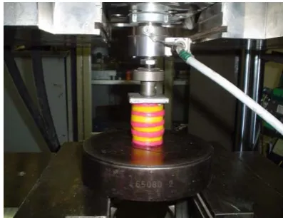
[image:2.595.337.516.176.465.2]Illustrated in Fig. 3, the compression test was performed under a 60 ton Zwick machine. The stress-strain diagram and its logarithmic form are presented in Fig. 4 and Fig. 5 respectively. The overall height and diameter of the billet was 55 and 36.6 mm respectively.
Fig. 3: Compression test performing on 60 ton press
D and p in the Herschel-Bulkley relationship are the
[image:2.595.326.525.559.712.2]Fig. 4: True stress- True strain Diagram
[image:3.595.311.551.148.747.2]Fig. 5: The logarithmic stress-strain diagram Physical and mechanical properties of plasticine have been listed in Table 1.
Table 1: Physical and mechanical properties of plasticine
Parameter Value
Density ρ=1221 Kg/m^3
Poison Ratio υ= 0.49 Young’s Modulus E= 4.2 MPa
Real Yield Stress σ = 0.13 MPa Multiplier; D= 2.1 Rate Dependent
Parameters Exponent; p=2.6
IV.
CONTACT DEFINITIONA combination of Columb and Constant friction factor was used to specify the boundary and contact conditions [17]. This friction model is known as Orowan’s friction law. The friction force at die/workpiece interface is defined as:
⎩ ⎨ ⎧
≥ ⇐ =
〈 ⇐ =
=
2 1 0 2
2 1 1
f f m
f
f f f f
ff n
A A τ μ
(3)
where fn is the distributed normal compressive force at interface, and τ0 is the shear yield stress which can be
defined as τ0 =σ0/ 3 with regard to von-misses criteria.
The columb friction coefficient μ andthe constant friction factor m are assumed as 0.05 and 0.2 respectively.
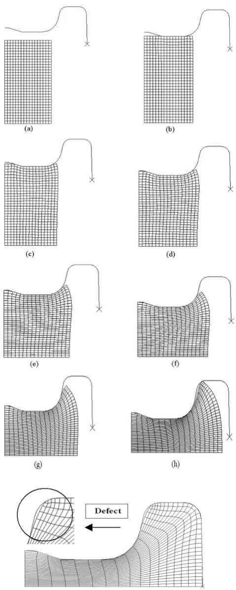
The billet was meshed into 780 quadrilateral axisymmetric elements and die surfaces were assumed rigid. The results of finite element analysis of the forging process have been illustrated in Fig. 6.
[image:3.595.69.270.509.612.2]As it can be seen in Fig. 6, the under filling defect in the final forging part is obvious. To eliminate this geometrical defect, an appropriate preform shape is required. In the next section preform design using interpolation approach is discussed.
The effective plastic strain distribution in the final part is shown in Fig. 7. According to Fig. 7, the maximum value of plastic strain in the final forging product is 2.43 and the strain deviation around the average value is 0.42.
Fig. 7: Effective plastic strain distribution through final part.
V.
PREFORM DESIGN BY INTERPOLATION OF BOUNDARY NODESTo start a preform shape interpolation scheme, an arbitrary number of interpolation stages are chosen. Next an arbitrary number of boundary nodes are determined. Subsequently, the final die and billet surfaces are divided to the same number of nodes. The coordinate of the points located at the billet surface can be defined as:
[ s s s s]
S X X X N X
X =0,Δ ,2Δ ,3Δ ,...,( −1)Δ
[ (0), ( s), (2 s), (3 s),..., (( 1) s)]
s f f X f X f X f N X
Y = Δ Δ Δ − Δ (4)
where N is the number of divided segments at the billet and
final die surfaces, and the subscript s represents the billet.
In the same manner, the coordinate of the points located at the final die is written as:
[ d d d d]
d X X X N X
X =0,Δ ,2Δ ,3Δ ,...,( −1)Δ
[ (0), ( d), (2 d), (3 d),..., (( 1) d)]
d f f X f X f X f N X
Y = Δ Δ Δ − Δ (5)
where the subscript d represents the final die.
Then, a backward linear Lagrange interpolation scheme is performed between final die and billet nodes. Therefore,
d
X and Yd would gradually tend toward Xs and Ys respectively in M interpolation stages. In this research work, M is considered as 10 interpolation stages. As a result, 10 preforms are produced during this interpolation scheme. The first preform should look similar to the final product and the last preform shape would essentially look very similar to the initial billet shape. Therefore, during this inverse process, the preform boundary shape can be obtained at each interpolation stage.
In theKth stage, the interpolation relationships for X and Y values is: ) / ( ) / 1
( k M X k M
X
X si
i d i
k = − + (6)
) / ( ) / 1
( k M Y k M
Y
Yki = di − + si
where
1
<
i
<
N
and the following boundary condition should be satisfied:d k d k s k s k Y Y X X k IF Y Y X X M k IF = = = = = = , ; 0 : , ; : (7)
In order to avoid any volume inconsistency during interpolation process, a volume correction factor was implemented. The correction factor C is expressed as:
3 /
k d V
V
C= (8)
Where Vd, Vk represent the volume of final die and Kth interpolated preform respectively. Consequently, the coordinate of the interpolated shapes is then modified by:
i k i
k Modified cX
X ( )= .
i k i
k Modified cY
Y ( )= . (9)
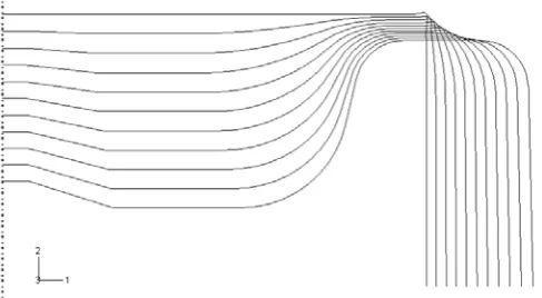
[image:4.595.64.269.179.299.2] [image:4.595.309.553.386.520.2]The Lagrange interpolation results and inverse shape evolution of the final die towards initial billet are shown in Fig. 8.
Fig. 8: Lagrange interpolation process between final die and billet shapes in 10 steps
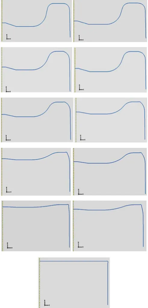
In Fig. 8, nodal coordinates are updated in the reverse direction towards the initial billet shape. Each interpolated shape can be chosen as a preform shape. However, a boundary condition expressed in Eq. (7), must be satisfied for the vertical walls. This will ensure the shape of preform at beginning and end of interpolation process. In this paper the first and last interpolated shapes are called preforms number 0 and 10 respectively. The other shapes among them would be numbered from 2 to 9 (See Fig. 9).
Fig. 9: Ten obtained interpolated preform shapes
The FE results showed that the preform no. 5 which was obtained from 5th interpolated shapes can be considered as
[image:5.595.46.292.64.577.2]an optimum preform. As it can be seen in Fig. 10, this preform has reduced under filling defect dramatically.
Fig. 10: Two stage forging using preform number 5 and elimination of geometrical defects in the final part
The plastic strain distribution after forging using this preform is shown in Fig. 11.
Fig. 11: Effective plastic strain distribution after forging with preform number 5
[image:5.595.311.539.99.233.2]From plastic strain distribution in Fig. 11, it can be concluded that preform no. 5 has improved the plastic strain deviation criteria. This comparison is presented in Table.2. In this table, the finite element results of forging process using preforms no. 4, 5, 6 and 7 have been listed.
Table 2
Strain distribution by using different preforms
Process PEEQ
(Max)
Scatter
(S)
Forging with final die 2.43 0.42 Forging with preform no. 4 & final die 2.14 0.38
Forging with preform no. 5 & final die 2.11 0.35
Forging with preform no. 6 & final die 2.13 0.36 Forging with preform no. 7 & final die 2.41 0.35
In Table 2, the maximum value for accumulated effective plastic strain is reported for all preforms. Preform no. 5 has the lowest value amongst others (PEEQ=2.11). Moreover, a minimum value of 0.35 for the deviation (scatter) of accumulated effective plastic strain is shown in this table. Therefore, it can be concluded that preform no. 5 is the most optimum preform among ten interpolated preform shapes. Thus, application of this preform in forging operation can reduce geometrical defects in the final part. In addition, a more uniform strain distribution through final part is achieved. As a result, superior geometrical and mechanical properties in the final forging product can be attainable.
VI.
CONCLUSIONIn this paper, a method based on the interpolation technique was employed to design forging preform shapes.
To perform interpolation scheme the initial billet shape and desirable final forging shape is required. A linear Lagrange interpolation scheme in definite number of stages is conducted. The obtained interpolated shapes can be used as preform shapes.
[image:5.595.46.288.654.761.2]was found that the geometrical quality of the final forging can dramatically be increased by the obtained preform shape. Furthermore, the plastic strain distribution in the final part becomes more uniform when this preform is used. As a result, the metallurgical and mechanical properties of final forging product can significantly be improved.
REFERENCES
[1] J. J. Park, N. Rebelo, S. A. Kobayashi, “A new approach to preform design in metal forming with the finite element method,” Int. J. Mach. Tool Des. Res. 23, 1983, pp. 71-79.
[2] S. M. Hwang, S. Kobayashi, “Preform design in disk forging,” Int. J. Mach. Tool Des. Res. 26, 1986, pp. 231-243.
[3] B. S. Kang, N. Kim and S. Kobayashi, “Computer-aided preform design in forging of an airfoil section blade,” Int. J. Mach. Tool Manuf. Vol.30, 1990, pp. 43-52.
[4] D. W. Kim, H. Y. Kim, “Preform design for axisymmetric closed-die forging by the upper bound elemental technique (UBET), The WAM, MD-vol.20, RED-vol.48, ASME, Dallas, TX, USA, 1990, pp. 155-164.
[5] S. Badrinarayanan, and N. Zabaras, “A Sensitivity Analysis for the Design of Metal Forming Processes,” Comput. Methods Appl. Mech. Eng., Vol.129, 1996, pp. 319–348.
[6] G., Zhao, E. Wright, and R. Grandhi, “Preform Die Shape Design in Metal Forming Using Optimization Method,” Int. J. Numer. Methods Eng., 40, 1997, pp. 1213–1230.
[7] M. Almohaileb, J. S. Gunasekera, B. V. Mehta, and B. Oyekarmi, ,“Modified Upper Bound Elemental Technique _MUBET_ for Preform Design in Closed Die Forging,” AIP Conference Proceedings, No. 712, Part 2, S. Ghosh, J. C. Castro, and J. K. Lee, eds., 2004, pp. 2062–2067.
[8] N. Thiyagarajan and V. R. Grandhi, “Multi-level design process for 3-D preform shape optimization in metal forming,” J. M. Proc. Tec., Vol.170, 2005, pp. 421-429.
[9] S.R. Lee, Y.K. Lee, C.H. Park and D.Y. Yang, “A new method of preform design in hot forging by using electric field theory”, Int. J. Mech. Sci., Vol. 44, 2002, pp. 773-792.
[10] T. Takemasu, V. Vazquez, B. Painter, and T. Altan, “Investigation of metal flow and preform optimization in flashless forging of a connecting rod,” J. Mater. Process. Technol. Vol.59, 1996, 95-105. [11] S. I. oh, and S. M. Yoon, “A new method to design blocker, “Ann.
CIRP 43, 1994, pp.245-248.
[12] S. R. Lee, “Optimal design of preform in hot forging,” MS Thesis, KAIST, 2000.
[13] A. Srikanth, N. Zabaras, “Shape optimization and preform design in metal forming processes,” Comp. Meth. Appl. Mech. Eng. Vol.190, 2000, pp. 1859-1901.
[14] F. R. Biglari, N. P. O’Dowd, and R. T. Fenner, “Optimum design of forging dies using fuzzy logic in conjunction with the backward deformation method”, Int. J. Mach. Tool Manuf. Vol.38, 1998, pp. 981-1000.
[15] H. Sofuoglu, and J. Rasty, “Flow behavior of plasticine used in physical modeling of metal forming processes”, Tribol. Int. Vol.33, 2000, pp. 523–529.
[16] M.J. Adams, I. Aydin, B.J. Briscoe, and S.K. Sinha, “A finite element analysis of the squeeze flow of an elasto-viscoplastic paste material”, J. Non-Newtonian Fluid Mech. Vol. 71, 1997, pp. 41–57.