Abstract— Formal Methods are very tough subject to student. It happens because of mathematics involvement during the development. Students normally feel very difficult to derive formal specification from informal requirement. In this paper, we propose an approach to deriving formal specifications from informal requirement using Venn diagram for creating formal specification. We show how to convert the Venn diagram to formal specification which is important part during development of Z schema. Then we do analysis of an assignment given to a group of student. With this approach student will easier to understand the operation of the system during Z schema development.
Index Terms— Venn diagram, Z schema, informal requirement, and formal specification.
I. INTRODUCTION
The complexity of modern software systems raise rapidly over recent years as a result of rising number of requirements for a new system. Complexity of requirement will rise up the difficulty of system development process. This problem is crucial for high reliable systems whose development often requires the critical areas. Formalization becomes a difficult task especially to understand and verify the complex specification [1].
There have been numerous approaches trying to propose different solutions to this problem. Some of them [1, 2, 3, 4] are focus more on describing requirements of complex system formally, usually by proposing different requirement languages. However, handling understandability problem still remain the major issue to student whose not have experience in deriving formal specification from informal requirement. The informal requirement is the requirement needed by the customer before the system to be developed by developer.
In this paper, we proposed an approach to make student understand the formal specification using Z schema from informal requirements specification with conversion Venn diagram to Z notation called Venn Requirement Language (VRL). The illustration is used to make it understand by an example Assessment for Emergency Response and Preparedness in the area of safety and health. The process starts from the informal statement to logic statement.
Manuscript received August 14, 2008. Venn Requirement Languages in Specification Languages.
M. S. Roslina is with the Universiti Malaysia Pahang, Locked Bag 12, 25000 Kuantan Pahang, Malaysia. (Phone: 609-5492104; fax:609-549-2133; e-mail: [email protected]).
A. Noraziah, Dr., is with the Universiti Malaysia Pahang, Locked Bag 12, 25000 Kuantan Pahang, Malaysia. (Phone: 609-5492121; fax:609-549-2133; e-mail: [email protected]).
Depending to this logic statement we set up a basic type of the system and initial state of the system. Then, we create a Venn diagram to show the relation between basic types that involve in the system. From the Venn diagram we convert into state schema.
The advantages of this VRL first student prefer visualization or graphical rather than text approaches. In this approach we are using Venn diagram as a tool so it shows the operation involves in system. Second, if student clearly understand to derive the Z schema yet the construct of schema will faster than using text. Third, using VRL automatically they used logic of the process by refer to the Venn diagram that created. The disadvantages of this VRL the Venn diagram only shows the basic operation of the system. Detail of the system it should combine with other technique to more understandable of the operation.
This paper is structured as follows: in Section 2 we discuss related work of this research. Section 3 describes the Venn diagram. Section 4 presents the informal requirement in Emergency Response and Preparedness. This section explains how to do individual assessment that relate on the skill, knowledge and attitude. In Section 5 we discuss our proposed model namely VRL. Section 6 we discuss the Z schema and will show the transformation of Venn diagram to Z schema. Finally, we conclude the paper in Section 7.
II. RELATED WORK
In this section we review some of the replica techniques mainly to increase understandability of creating formal specification which are using UML class diagram [2], UML and Contract Box [3] and SAM [4]. The proposed techniques were using visualization ways to make formal specification more understandable. It is because majority of students on computer science courses express the conversion informal requirement to formal specification whereas they are comfortable using graphical program [2]. Graphical representations are good to help student to clear understand the structures, compositions and relations between elements that occur in any system. It also aids the process of the process of formal specification.
The research have been made by Snook C et al proposed UML class diagram is one of the way to make formal specification more understandable [2]. Class Diagram in UML allow the type of objects in the problem domain and the relationships between them to be modeled, visualized, prototyped and altered quickly. The reason is the model is highly visible and easily alterable with the aid of the graphical design tools. Then, the UML model translated to B specification. The example of Snook proposed refer is to Fig I.
Venn Requirement Language in Specification
Languages
Fig I: Example of Class Diagram and Class Specification The example shows a class GAME that has typed and initialized attributes, parameterized operations (some with return values), three association relationships with a class TICKET, PRIZE and PLAYER, as a type. The associations have role names Prizes, Tickets, Winners and Claimed, which are used to refer to the instances of the associated class involved in the association. Alongside the class diagram is shown the Rational Rose specification for the class GAME. Following the natural language description in the ’Documentation’ box some class invariants are given. Then, they construct the formal specification with precondition and semantics as shown in Fig II.
Fig II: Precondition and Semantics for operation buyof class GAME
From the paper they conclude UML diagram assist in the difficult task of creating appropriate models and make formal specification more approachable.
While, Soon Kyeong Kim and David Carrington were proposed various diagram to enhance formal specification to be readable and understandability of the Z specification. They used UML class diagram as a tool to make clear the
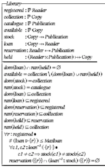
[image:2.595.59.279.67.232.2]operation of the informal requirement to visualize the system structure specified in the state schema. Then, Contract Box to express the pre and post state of Z operation [3]. They visualize the Library system using UML like Fig III.
Fig III: UML for Library System for Z - state Schema
[image:2.595.322.534.118.268.2]The Fig. IV shows the Z schema for Library System.
Fig IV:Z State Schema for Library System
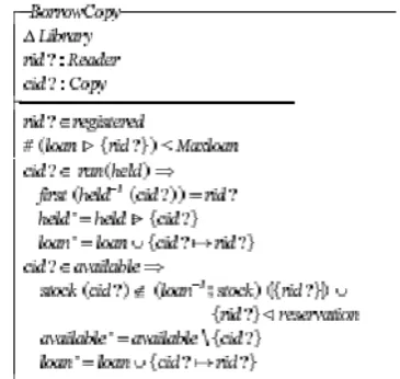
[image:2.595.320.492.349.623.2]Fig. V: Contract Box of BorrowCopy Operation The Contract Box to show the Z schema in Fig. VI as show below:
Fig. VI: Z Schema for BorrowCopy Operation
They concluded their proposed visualize diagram was structured way to read and understand the Z specification.
X. He et al. proposed Software Architecture Model (SAM) to present graphical formal software architecture which is based on Petri Nets and temporal logic to improve understandability and reduce complexity. The Petri Nets are used to define the behavior models of components and connectors while temporal logic is used to specify properties of component and connector [4]. The architecture is illustrated as a set of boxes with port connected by arrows. The boxes called composition. Each composition contains other compositions. The bottom-level compositions are either components or connectors. Various constraints can be specified. This hierarchical model supports compositionality in both software architecture design and analysis. Thus, facilitate scalability. Fig. VII shows a graphical view of an SAM software architecture, in which connectors are not emphasized and are only represented by thick arrows.
[image:3.595.326.527.54.187.2]In this paper, we propose Venn Requirement Language to visualize the process of any system which is using Venn diagram. With this VRL student clear understand the formal specification.
Fig. VII: A graphical SAM architecture
Submit your manuscript electronically for review.
III ELEMENTS OF SYSTEM MODEL
The elements in our system model are Venn diagram, ERP and Z notation.
A. Venn Diagram
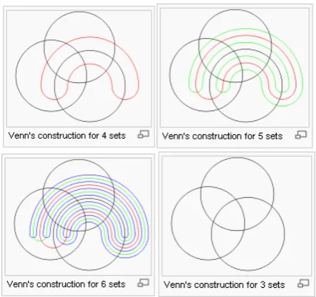
Venn diagrams are invented in 1881 by John Venn. It is used to visualize in the branch of mathematics known as set theory. It shows all of the possible mathematical or logical relationships between sets groups of things. They normally consist of overlapping circles. In a two-set Venn diagram, one circle may represent the group of all wooden objects, while another circle may represent the set of all tables. The overlapping area intersection would then represent the set of all wooden tables. Shapes other than circles can be employed shown in Fig.VII:
Fig. VIII:Venn Diagram shown set A and B
[image:3.595.77.260.261.434.2]Fig. IX : Venn Diagram with more 2 sets
B. System Model Emergency Response and Preparedness (ERP)
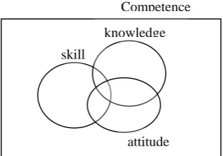
[image:4.595.306.547.446.682.2]Emergency Response and Preparedness is a plan to handle anticipated emergencies prior to the commencement of emergency response operations [7]. The competencies may be defined as a complex combination of knowledge, skills, and abilities demonstrated by members of an organization that are critical to the effective and efficient function of the organization as shown in Fig. X.Competency statements describe specific activities that individuals are able to do or perform depending on their respective roles, responsibilities, and qualifications. Competency resources have been developed for a full range of public health services,including emergency response8 and legal preparedness.
Fig. X: Competence Creation
Knowledge is a very important component to measure the competency. If the persons do not have knowledge of tool, experience to handle danger or hazard, they may do not know what to do during the emergencies happen. It also refers to what you need to know. Skill is refers to what you must be able to do. The person should skillful in the learnt capacity or talent to carry out pre-determined results often with the minimum outlay of time, energy, or both. For example, in the domain of work, some general skills would include time management, teamwork and leadership, self motivation and others, whereas domain-specific skills would be useful only for a certain job [5]. While, attitude is refer to what you need to believe and feel. It is the preference of an individual or
organization towards or away from things, events or people. It is the spirit and perspective from which an individual, group or organization approaches community development. Your attitude shapes all your decisions and actions. Attitude is very difficult to define with precision as it consists of qualities and beliefs that are non-tangible. We are used to talking about the attitude of individuals, but it is important to recognize that organizations also have attitude. Usually, however, when we talk about an organization’s attitude we use the term “organizational culture”.
C. Z methodss
The Z systems are modeled using sets and relations between sets. This method is an approach for the industrial development of highly dependable software. It has been successfully used in the development of complex real-life application be it constructs specification in software specification. The use of mathematical statement will make very hard to understand the process of the system. Also, set and relation between sets in mathematic we can show using the Venn diagram. The formal description is easy to chunks that are distinguished from association text using graphical highlighting called schema. It used to introduce state variables, define constraints and operation on the state [6].
IV. VENN REQUIREMENT LANGUAGES (VRL) In this section, we present a broad overview of our approach to handling state schema in informal requirement. Fig. XI shows the graphical depiction of the entire process.
Fig. XI: VRL Model
In the course of the requirements evolution process, requirements are introduced by the stakeholders. At this stage, requirements are expressed in natural language sentences. Each stakeholder can state the requirements that are significant from their point of view. The informal
---… …
A & ~b -> c p->a
Logic Formulae Venn Diagram
Specification
Theorem and Prove
Write / Modify
Correction
[image:4.595.82.258.521.575.2]requirement then submitted to VRL (Venn Requirement Logic) and subjected to a series of transformation: (i) translate the informal requirement to propositional statement (ii) create the state schema.
The state schema then added to the specification which is represents the theory of user need or requirement. Venn diagram makes the developer easier to translate to the state schema which is to show the environment of the requirement. If there is theorem prove checked that the requirement is invalid, then, it will ask for certain modification.
We choose one area to show how the VRL works in ERP (Emergency Response and Preparedness). The area of ERP is concentrating on the individual assessment. The steps that we proposed are like below:
Step 1: Get the informal requirements
Step 2: Identify the critical part in the requirement Step 3: Transform into Propositional statement Step 4: Create the VRL based on the step 3 Step 5: Create the whole schema using Z notation Step 6: Proving.
Refer to the problem given the step are; Step 1: Get the informal requirements
The informal requirement is the requirement that we need to get for development of any system. We show the example of assessing the individual competency in Emergency Response and Preparedness (ERP). The informal requirement for assess individual competency is an objective description of the knowledge, skills, and abilities an individual must perform a position or a function role so that their actions contribute to organizational success.
Step 2: Identify the critical part in the requirement.
The stakeholder requirement is about individual assessment in healthcare so and the competencies are an objective description of the knowledge, skills, and abilities an individual must perform a position or a function role so that their actions contribute to organizational success [5].
The knowledge, skill and ability on job are the key or main point inside the ERP systems.
Step 3: Transform into Propositional statement
The statements that we can transform to propositional statement are:
“If individual is having knowledge, skill but no ability on his job then he is not competence. If individual is not knowledgeable then he is not competence. Therefore, when individual is knowledgeable, skill and ability on his job is competence.”
Key assumption: p : knowledgeable q : skill
[image:5.595.301.528.62.230.2]r : ability to do z : competence
Table I: Statement to Propositional Statement
Statement Proposition statement
If individual is having knowledge, skill but no ability on his job then he is not competence
p ∧ q ∧ ⌝ r → ⌝ z
If individual is not knowledgeable then he is not competence
⌝ p → ⌝ z
Therefore, when individual is knowledgeable, skill and ability on his job is competence.
p ∧ q ∧ r → z
Step 4: Create the VRL based on the step 3
[image:5.595.304.464.353.465.2]The Venn diagram concept we can say A = B ¾ C ¾ D. So, in the informal requirement we can show the logic of the system in individual competency is individual competency = skill ¾ knowledge ¾ able to response. The Venn diagram will appear as Fig. XII:
Fig. XII: Competency Venn diagram
From the above Venn diagram shows that if individual knowledge with no skill and not able to response, the individual is still not competency. If individual is having a skill but not knowledgeable and not able to response, also not competence. Unless the individual is having skill with knowledgeable and able to response the emergency then we can assume competence.
Step 5: Create the state diagram for the system.
staff
Competency = skill ¾ knowledge ¾ attitude
In Z, a specification is represented by a schema. From the above informal requirement firstly, we need to define the basic type of the individual assessment. We assumed here individual is a type of person or staff for any company, [STAFF]. We can classified the staff is competence if and only the staff already skill in their job, having the knowledge
skill
knowledge
attitude Competence
and the attitude during response the emergency. If the staff only have knowledge and skill but not fulfill the attitude means not competence yet. The response should be competenceOk, NotCompetence, SkillOk, KnowledgeOk, AttitudeOK. So, we can write with RESPONSE ::= CompetenceOk | NotCompetence | SkillOk | KnowledgeOk | AttitudeOK.
The main operation from the requirement is to classify the individual which is competence and fulfill the knowledge, skill and attitude. In Fig. XIII also shows the state schema of the system for the competence of staff.
Fig XIII: Skill Operation
Fig. XIV shows the adding of the staff that skill full in the ERP. The dot, shows the staff and the arrow, shows the direction of staff to add in the set of skill. The Z schema as shown below:
ó Competence s? : ¡ Staff resp ! : Response s? Skill
Skill’ = skill U {s? } Knowledge’ = knowledge Attitude’ = attitude Resp! = SkillOk
Fig. XIV: Z schema SkillOK
Fig. XV, shows the adding of the staff that knowledgeable in the ERP. It shows the operation of adding staff in the set of knowledge.
Fig. XV :Knowledge Operation
The Z schema of knowledge operation is shown like Fig. XVI:
ó Competence s? : ¡ Staff resp ! : Response s? knowledge Skill’ = skill
Knowledge’ = knowledge U {s? } Attitude’ = attitude
Resp! = KnowledgeOk
Fig. XVI: Z Schema for KnowledgeOK
Fig. XVII shows the adding of the staff that attitude is OK in the ERP. The dot, shows the staff and the arrow, shows the direction of staff to add in the set of attitude.
Fig. XVII :Attitude Operation
Fig. XVIII shows the Venn diagram the Z schema of attitude operation. :
ó Competence s? : ¡ Staff resp ! : Response s? attitude Skill’ = skill
Knowledge’ = knowledge Attitude’ = attitude U {s? } Resp! = AttitudeOk
Fig. XVIII: Z schema for AttitudeOK
V. ANALYSIS OF PERFORMANCE
Because the final formatting of your paper is limited in scale, you need to position This assessment already given to our student of Formal Methods subjects this semester 2 and session 2007/2008. An assignment was given to them to create a Z schema of their system. We took sample for 86 skill
knowledge
attitude Competence
y
y
y
y
SkillOk
knowlegeOk
AttitudeOk
skill
knowledge
attitude Competence
y
skill
knowledge
attitude Competence
students of Faculty of Computer Systems and Software Engineering to assess their result of assignment. We set three level of understandable of formal specification based on the Venn diagram. The levels are Not Understand which between 0 and 50 mark, Understand is between 51 and 70 marks and Really Understand between 71 and 100 marks. The marks we took from presentation of the assignment. The results are shown in Table 1. Table show the parameter of understandable of Formal Specification using VRL
Table 1: Result of Understandable of Formal Specification using VRL
Level Number of Student Percentage Not
Understand (0 – 50)
15 18
Understand (51 – 70)
45 52
Really Understand
(71 – 100)
26 30
Total 86 100
Most of them can create the operation of the system with 82%. It means that they understand how to create the Z schema using the proposed method.
VI. CONCLUSION
In this paper we described an approach to make student understand the state schema and operation involved in system using Venn diagram. We illustrated the transformation process by an example – Individual Assessment for Emergency Response and Preparedness in the area of safety and health. The informal requirement and operation were illustrated using Venn diagram to make student understand about the operation of the system. From the analysis, it shows the VRL assist difficult understand about the Z specification especially for those who not very familiar with this formal specification. Therefore, this paper presents the new novel contribution in understandability of formal specification from informal requirement.
ACKNOWLEDGMENT
This research was based on Faculty of Computer Systems and Software Engineering Course Subjects which is Formal Methods. This subject has been offer for student only 4 semesters. Hopefully, VRL can help in teaching.
REFERENCES
[1] D. Ilic,, “Deriving Formal Specifications from Informal
Requirements”, 31st Annual International Computer Software and
Applications Conference(COMPSACT 2007), IEEE
[2] C. Snook, and M. Butler, “Using a Graphical Design Tool for Formal Specification”, 13th Workshop of the Psychology of Programming
Interest Group, Bournemouth UK, April 2001 pp. 311 – 321 [3] S. K. Kim, and D. Carrington, Technical Report: Visualization of
Formal Specifications, Queensland December 1992,
[4] X. He et al, “Formally analyzing software architectural specifications using SAM”, The Journal of Systems and Software 71, Science Direct, Florida International University, Miami., August 2004, pp. 11-29
[5] G. James, et al, “Assessing Competencies for Public Health Emergency Legal Preparedness”, Journal of Law, Medicine & Ethics, The National Action Agenda for Public Health Legal Preparedness [6] Sommerville, 2007. Software Engineering, Addison Wesley pp 218
-238
[7] Wikipedia, http://en.wikipedia.org/wiki/Skill, 7 April 2008 [8] Hazardous waste operations and emergency response, Occupational