warwick.ac.uk/lib-publications
Permanent WRAP URL:
http://wrap.warwick.ac.uk/99446/
Copyright and reuse:
This thesis is made available online and is protected by original copyright.
Please scroll down to view the document itself.
Please refer to the repository record for this item for information to help you to cite it.
Our policy information is available from the repository home page.
Novel Block Copolymer Systems Prepared
via
RAFT
Polymerisation
Liam Thomas Martin
A thesis submitted in partial fulfilment of the requirements for the degree of
Doctor of Philosophy in Chemistry
Department of Chemistry
University of Warwick
Page | ii
List of Figures ... ix
List of Tables ... xvi
List of Schemes ... xx
Abbreviations ... xxi
Acknowledgements ... xxvi
Declaration ... xxix
List of Publications ... xxx
Chapter 1 – Introduction ... 1
– Block Copolymers ... 1
1.1 – Reversible Deactivation Radical Polymerisation (RDRP) ... 2
1.2 – RAFT Polymerisation ... 2
1.3 1.3.1 – The mechanism of RAFT ... 3
1.3.2 – Control of molar mass ... 4
1.3.3 – Control of molar mass distribution ... 6
– Synthesis of Block Copolymers ... 8
1.4 1.4.1 – Block copolymers via sequential RAFT polymerisations ... 8
1.4.2 – Alternative synthetic approaches to block copolymers ... 10
– Multiblock Copolymers ... 11
Page | iii
1.6
– References ... 16
1.7
Chapter 2 – Preparation of Complex Multiblock Copolymers
via
RAFT
Polymerisation at Room Temperature ... 23
– Introduction ... 24
2.1 – Results and Discussion ... 26
2.2 2.2.1 – Establishing conditions for redox initiated aqueous RAFT ... 26
2.2.2 – Sequential addition multiblock homopolymer synthesis at 25 °C vs 70 °C ... 30
2.2.3 – Preparation of acrylamide-based multiblock copolymers at 25 °C ... 38
2.2.4 – Preparation of acrylate-based multiblock copolymers at 25 °C ... 40
2.2.5 – Preparation of acrylate/acrylamide-based multiblock copolymers at 25 °C ... 42
– Conclusion ... 44
2.3 – Experimental ... 45
2.4 2.4.1 – Materials ... 45
2.4.2 – Methods... 45
– Nuclear Magnetic Resonance (NMR) Spectroscopy ... 45
2.4.2.1 – Size Exclusion Chromatography (SEC) ... 46
2.4.2.2 – Determination of DPn,targeted and monomer conversion ... 46
2.4.2.3 – Determination of Mn,th ... 46
2.4.2.4 2.4.3 – Multiblock copolymer synthesis via sequential addition RAFT polymerisation 47 – Typical synthesis of initial block ... 47
Page | iv
2.4.3.2
- References ... 49
2.5 – Supporting information ... 54
2.6
Chapter 3 – On the Use of Redox initiation in Aqueous RAFT polymerisation 75
– Introduction ... 763.1 – Results and Discussion ... 79
3.2 3.2.1 – Choice of redox pair and ox/red stoichiometry ... 79
3.2.2 – Rapid aqueous RAFT at 50 °C ... 89
3.2.3 – Polymerisation in the presence of oxygen ... 91
– Conclusion ... 93
3.3 – Experimental ... 95
3.4 3.4.1 – Materials ... 95
3.4.2 – Methods... 95
– Nuclear Magnetic Resonance (NMR) Spectroscopy ... 95
3.4.2.1 – Size Exclusion Chromatography (SEC) ... 95
3.4.2.2 – Determination of DPn,targeted and monomer conversion ... 96
3.4.2.3 – Calculation of Mn,th ... 96
3.4.2.4 3.4.3 – Synthesis ... 96
– Preparation of aqueous solutions of oxidising/reducing agents ... 96
3.4.3.1 – Procedure for polymerisation kinetics ... 97
Page | v
3.4.3.3
– References ... 98
3.5 – Supporting information ... 103
3.6
Chapter 4 – Investigating the Cell-Uptake Behaviour of Guanidinium-Rich
RAFT (co)Polymers: Influence of co-Monomer and Monomer Distribution... 104
– Introduction ... 106
4.1 – Results and Discussion ... 109
4.2 4.2.1 – Synthesis of BOC-protected guanidine ethyl acrylamide (GEAdiBOC) ... 109
4.2.2 – Synthesis of guanidinium-rich homopolymers via RAFT polymerisation ... 110
4.2.3 – Cellular uptake of pGEA homopolymers vs polyArginines ... 112
4.2.4 – Synthesis of guanidine-rich copolymers via RAFT polymerisation ... 118
4.2.5 – Influence of comonomer on cell uptake ... 121
4.2.6 – Influence of copolymer segmentation on cell uptake ... 124
– Conclusion ... 127
4.3 – Experimental ... 128
4.4 4.4.1 – Materials ... 128
4.4.2 – Methods... 128
– Nuclear magnetic resonance (NMR) spectroscopy ... 128
4.4.2.1 – Calculation of Mn,th ... 129
4.4.2.2 – Size exclusion chromatography (SEC) ... 129
4.4.2.3 – Analytical high performance liquid chromatography (HPLC) ... 129
Page | vi
4.4.2.5
– Cell lines ... 130
4.4.2.6 – Cytotoxicity assays ... 130
4.4.2.7 – Confocal microscopy ... 130
4.4.2.8 – Cellular uptake experiments ... 131
4.4.2.94.4.3 – Synthesis ... 132
– Synthesis of polyArginine and fluorescein-polyArginine ... 132
4.4.3.1 – Synthesis of 1,3-Di-Boc-guanidinoethyl acrylamide, GEAdiBOC ... 132
4.4.3.2 – Block copolymers synthesis (diblock and tetrablocks) by sequential RAFT 4.4.3.3Polymerisation ... 133
– Deprotection of polymers ... 134
4.4.3.4 – Attachment of Fluorescein Cadaverine ... 134
4.4.3.5 - References ... 135
4.5 – Supporting information ... 139
4.6
Chapter 5 – Exploiting Carbohydrate-Lectin Selectivity to Modulate the
Response of Giant Glycosylated Polymersomes Towards Bacteria ... 155
– Introduction ... 157
5.1 – Results and Discussion ... 160
5.2 5.2.1 – Synthesis of PDMS-PBTC ... 160
5.2.2 – RAFT polymerisation of BEA with the PDMS-PBTC macro-CTA ... 162
Page | vii 5.2.5 – Formation of giant glycosylated polymersomes (GGPs) and their interaction
with fimH positive E. coli ... 173
– Conclusion ... 175
5.3 – Experimental ... 177
5.4 5.4.1 – Materials ... 177
5.4.2 – Methods... 177
– Nuclear Magnetic Resonance (NMR) Spectroscopy ... 177
5.4.2.1 – Size Exclusion Chromatography (SEC) ... 178
5.4.2.2 – Differential scanning calorimetry (DSC) ... 178
5.4.2.3 – Dynamic light scattering (DLS) ... 178
5.4.2.4 – Static light scattering (SLS) ... 178
5.4.2.5 – Transmission electron microscopy ... 179
5.4.2.6 – Confocal fluorescence microscopy ... 179
5.4.2.7 – UV/Vis turbidity experiments ... 179
5.4.2.8 – GGP interactions with E. coli... 179
5.4.2.9 5.4.3 – Synthesis ... 180
– Synthesis of 2-bromoethyl acrylate (BEA) ... 180
5.4.3.1 – Synthesis of PDMS-PBTC macro-CTA ... 180
5.4.3.2 – Synthesis of PDMS-pBEA diblock copolymers ... 181
5.4.3.3 – Post-polymerisation substitution with 1-thio-β-D-glucose ... 181
5.4.3.4 – Post-polymerisation substitution with 1-thio-β-D-galactose ... 182
Page | viii
5.4.3.6
– Self-assembly of PDMS-glycopolymers via Electroformation process .... 182
5.4.3.7
- References ... 184
5.5
– Supporting information ... 189
5.6
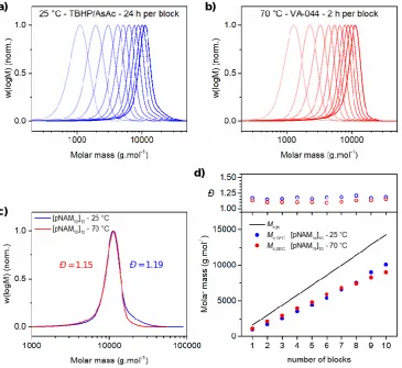
Page | ix Figure 2.1 – Comparison of (pNAM10)10 prepared at 25 °C (redox) and 70 °C (azoinitiation). THF-SEC chromatograms following each block synthesis in the preparation of (pNAM10)10via redox initiated RAFT at 25 °C (a) and VA-044 initiated RAFT at 70 °C (b). THF-SEC chromatograms of final (pNAM10)10 prepared via redox initiated RAFT at 25 °C (blue) and VA-044 initiated RAFT at 70 °C (red) (c). Evolution of experimental molar mass (Mn,SEC) and molar mass distribution (Đ) for each block synthesis in the preparation of (pNAM10)10 at 25 °C (blue) and 70 °C (red) as determined by THF-SEC (d). ... 31
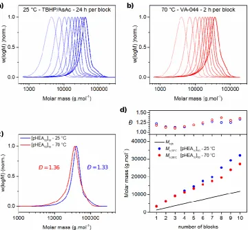
Figure 2.2 – Comparison of (pHEA10)10 prepared at 25 °C (redox) and 70 °C (azoinitiation). DMF-SEC chromatograms following each block synthesis in the preparation of (pHEA10)10 via redox initiated RAFT at 25 °C (a) and VA-044 initiated RAFT at 70 °C (b). DMF-SEC chromatograms of final (pHEA10)10 prepared via redox initiated RAFT at 25 °C (blue) and VA-044 initiated RAFT at 70 °C (red) (c). Evolution of experimental molar mass (Mn,SEC) and molar mass distribution (Đ) for each block synthesis in the preparation of (pHEA10)10 at 25 °C (blue) and 70 °C (red) as determined by DMF-SEC (d). ... 33
Figure 2.3 – Indication of initiator concentrations employed for each block synthesis in preparation of multiblock homopolymers using redox initiated aqueous RAFT polymerisation at 25 °C. ... 35
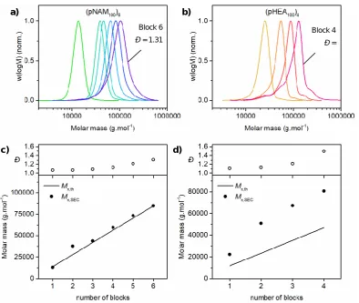
Figure 2.4 – DMF-SEC data for synthesis of pNAM and pHEA multiblock homopolymers with a targeted DPn of 100 per block. DMF-SEC chromatograms after each
successive block synthesis in the preparation of (pNAM100)6 (a) and (pHEA100)4 (b) at 25 °C using redox initiated aqueous RAFT. Evolution of experimental molar mass (Mn,SEC) and molar mass distribution (Đ) with each successive block synthesis for (pNAM100)6 (c) and (pHEA100)4 (d). ... 36
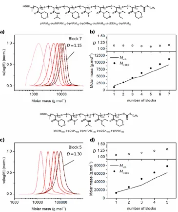
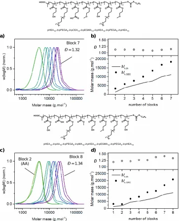
Page | x DMF-SEC chromatograms (a/b) and evolution of experimental molar mass (Mn,SEC) and molar mass distribution (Đ) (c/d) with each successive block synthesis in the preparation of pHEA10-b-pPEGA5-b-pCEA10-b-pEGMEA10-b-pHEA10-b-pPEGA5-b-pEGMEA10 (a and c) and pHEA10-b-pAA10-b-pPEGA5-b-pMA10-b-pHEA10-b-pEGMEA10-b-pPEGA10-b-pHEA10 (b and d) at 25 °C using redox initiated aqueous RAFT polymerisation. ... 41
Figure 2.7 – DMF-SEC data for synthesis of acrylate/acrylamide-based multiblock copolymer. DMF-SEC chromatograms (a) and evolution of experimental molar mass (Mn,SEC) and molar mass distribution (Đ) (b) with each successive block synthesis in the preparation of pHEA10-b-pAA10-b-pPEGA5-b-pMA10-b-pNAM10-b-pNIPAM10-b-pDMA10 at 25 °C using redox initiated aqueous RAFT polymerisation. ... 43
Figure 2.8 – UV-channels from DMF-SEC of acrylate-based multiblock copolymers prepared in this work. ... 74
Figure 3.1 – Polymerisation kinetics for redox-initiated RAFT polymerisation of poly(NAM) in H2O:dioxane (90:10) at 30 °C using an Ox/Red ratio of 1:1. Monomer conversion vs polymerisation time (a), pseudo-first-order kinetics (b) and evolution of molar mass and molar mass distribution with monomer conversion (c). [NAM]0 = 3.0 mol.L
-1 , [Ox]0 = 7.5 × 10⁻⁴ mol.L-1. ... 82
Figure 3.2 – Polymerisation kinetics for redox-initiated RAFT polymerisation of poly(NAM) in H2O:dioxane (90:10) at 30 °C using an Ox/Red ratio of 1.0.5 Monomer conversion vs polymerisation time (a), pseudo-first-order kinetics (b) and evolution of molar mass and molar mass distribution with monomer conversion (c). [NAM]0 = 3.0 mol.L
-1 , [Ox]0 = 7.5 × 10
-4
mol.L-1. ... 84
Figure 3.3 – Polymerisation kinetics for redox-initiated RAFT polymerisation of poly(NAM) in H2O:dioxane (90:10) at 30 °C using an Ox/Red ratio of 1:0.2. Monomer conversion vs polymerisation time (a), pseudo-first-order kinetics (b) and evolution of molar mass and molar mass distribution with monomer conversion (c). [NAM]0 = 3.0 mol.L
-1 , [Ox]0 = 7.5 × 10
-4
mol.L-1. ... 85
Page | xi mass and molar mass distribution with monomer conversion (c). [NAM]0 = 3.0 mol.L
-1 , [Ox]0 = 7.5 × 10⁻⁴ mol.L-1. ... 87
Figure 3.5 – Extremely rapid RAFT polymerisation of NAM at 50 °C. Plot of polymerisation kinetics, (a) DMF-SEC chromatograms at full monomer conversion (b) and evolution of molar mass and molar mass distribution with monomer conversion (c) for polymerisation of NAM conducted at 30 °C (blue) and 50 °C (black) in H2O:dioxane using the THBP/AsAc redox initiating system. [NAM]0 = 3.0 mol.L
-1
, [Ox]0 = 7.5 × 10 -4
mol.L-1 at 30 °C, 2.5 × 10⁻³ mol.L-1 at 50 °C, [TBHP]0/[Brug7]0 = 1:0.5. ... 90
Figure 3.6 – Monomer conversion achieved with different experimental setups (top). Experimental molar masses obtained via DMF-SEC vs monomer conversion (bottom) for the redox-initiated RAFT polymerisation of poly(NAM) in H2O:dioxane (90:10) at 30 °C. [NAM]0 = 3.0 mol.L
-1
, [TBHP]0 = 5.0 × 10 -4
mol.L-1. [TBHP]0 :[Brug7]0 = 1:0.5. The letters indicate Table 3.2 entries. ... 93
Figure 3.7 – DMF-SEC traces of poly(NAM) prepared via redox-initiated RAFT polymerisation in H2O:dioxane (90:10) at 30 °C using the redox couple TBHP/Brug7. [NAM]0 = 3.0 mol.L-1, [TBHP]0 = 5.0 10-4 mol.L-1, [TBHP]0/[Brug7]0 = 1:0.5. Letters correspond to entries in Table 3.2. The coding corresponds to experimental conditions; vessel – vial (V) or tube (T) / stirring – yes (Y) or no (N) / deoxygenated – yes (Y) or no (N) / open (O) or closed (C) reaction vessel. ... 103
Figure 4.1 – 1H NMR in DMSO-d6 of pGEA9 before (top) and after (bottom) deprotection... 111
Figure 4.2 – DMF-SEC of BOC-protected pGEA9 and pGEA20 prepared via RAFT polymerisation... 112
Figure 4.3 – Cytotoxicity of pGEA homopolymers and polyArginines. Viability of Caco2 cells incubated for 24 hours in the presence of various concentrations of (top) R9 and R20, (bottom) pGEA9 and pGEA20 as measured using XTT assay. ... 113
Figure 4.4 – Comparison of the cell uptake of polyArginine peptide vs RAFT polymer analogues (DPn = 9/20). Fluorescence intensity measured in MDA-MB-231 cells incubated
Page | xii analogues (DPn = 9/20). Fluorescence intensity measured in Caco2 cells incubated with 5
µM of R9, pGEA9, R20 and pGEA20 for the indicated time and temperature. ... 115
Figure 4.6 – Comparison of the cell uptake of polyArginine peptide vs RAFT polymer analogues (DPn = 20). Confocal microscopic analysis of the intracellular location of R20 and pGEA20 in live MDA-MB-231 cells following the indicated time and temperature. Cells were stained with LysotrackerTM Red and Hoechst 33342 to stain the lysosomes and nucleus, respectively. Co-localisation of the compounds with the lysosomes resulted in yellow spots in the overlay images. ... 117
Figure 4.7 – DMF-SEC chromatograms of copolymers prepared via RAFT
polymerisation. pDMA20-co-pGEA20 copolymers (top) and pHEAm20-co-pGEA20 copolymers (bottom) ... 120
Figure 4.8 - Cytotoxicity of guanidinium-rich copolymers. Viability of Caco2 cells incubated for 24 hours in the presence of various concentrations of homopolymers pGEA20, pGEA40, pDMA40 and pHEA40 (top), copolymers pDMAstat, pDMAtetra and pDMAdiblock (middle), and copolymers pHEAmstat, pHEAmtetra and pHEAmdiblock (bottom). ... 121
Figure 4.9 – Comparison of the cell uptake of RAFT guanidinium-rich copolymers with different monomer distributions. Fluorescence intensity measured in MDA-MB-231 cells incubated with 2 µM of DMAstat, HEAmstat, DMAtetra, HEAmtetra, DMAdiblock and HEAmdiblock for the indicated time and temperature. ... 122
Figure 4.10 – Comparison of the cell uptake of RAFT guanidinium-rich copolymers with different monomer distributions. Fluorescence intensity measured in Caco2 cells incubated with 2 µM of DMAstat, HEAmstat, DMAtetra, HEAmtetra, DMAdiblock and HEAmdiblock for the indicated time and temperature. ... 123
Page | xiii
Figure 4.13 – DMF-SEC of pDMA40, pHEAm40 and pGEA
diBOC
40 prepared via RAFT polymerisation... 146
Figure 4.14 – Fluorescent HPLC traces (λex = 490 nm, λem = 525 nm) of polyArginines R9 and R20 (top) and pGEA homopolymers pGEA9 and pGEA20 (bottom) following attachment of fluorescein dyes. ... 146
Figure 4.15 – DMF-SEC after each polymerisation step in the synthesis of pDMA-co -pGEAdiBOC copolymers prepared via RAFT polymerisation in one-pot. DMAstat (top), DMAtetra (middle), DMAdiblock (bottom). ... 147
Figure 4.16 – DMF-SEC after each polymerisation step in the synthesis of pHEAm-co-pGEAdiBOC copolymers prepared via RAFT polymerisation in one-pot. HEAmstat (top), HEAmtetra (middle), HEAmdiblock (bottom). ... 148
Figure 4.17 – 1H NMR of pDMA20-stat-pGEA20 (DMAstat) before (top) and after (bottom) removal of BOC protecting groups using TFA/TIPS/H2O. ... 149
Figure 4.18 – 1H NMR of pHEAm20-stat-pHEAm20 (HEAmstat) before (top) and after (bottom) removal of BOC protecting groups using TFA/TIPS/H2O. ... 150
Figure 4.19 – HPLC spectra at λ = 309 nm of homopolymers pGEA40, pDMA40 and pHEAm40 copolymers (top), DMAstat, DMAtetra and DMAdiblock (middle), HEAmstat, HEAmtetra and HEAmdiblock (bottom). The small peak observed at rt = 40 min was characterised by UV to have a maximum absorbance at λ = 312 nm and is therefore attributed to partial cleavage of the trithiocarbonate group. (not observed in pDMA40, pHEAm40). ... 151
Figure 4.20 – Fluorescent HPLC traces (λex = 490 nm, λem = 525 nm) of homopolymers pDMA40, pHEAm40 and pGEA40 (top), DMA-based copolymers DMAstat, DMAtetra, and DMAdiblock (middle) and HEAm-based copolymers HEAmstat, HEAmtetra, and HEAmdiblock (bottom). ... 152
Page | xiv (bottom), monohydroxy-terminated PDMS (middle), and PDMS-PBTC (top). ... 160
Figure 5.2 – 1H NMR (CDCl3) of the PDMS60-PBTC macroCTA (bottom) and purified PDMS60-b-pBEA6 (P1) (top) following 4 h of RAFT polymerisation at 66 °C in 1,4-dioxane. ... 164
Figure 5.3 – THF-SEC chromatograms of purified PDMS60-b-pBEA polymers following 4 h of RAFT polymerisation at 66 °C in 1,4-dioxane. ... 165
Figure 5.4 – HSQC spectra of P1Glu in THF-d8/MeOD (90/10) following post-polymerisation substitution of P1 with 1-thio-β-D-glucose. ... 166
Figure 5.5 – DSC curve of PDMS60-b-pBEA6 (P1) (black, top), PDMS60-b-pGluEA6 (P1Glu) (red, middle) and PDMS60-b-pGalEA6 (P1Gal) (blue, bottom). ... 167
Figure 5.6 DSC curve of PDMS60-b-pBEA16 (P2) (black, top), PDMS60-b-pGluEA16 (P2Glu) (red, middle) and PDMS60-b-pGalEA16 (P2Gal) (blue, bottom). ... 168
Figure 5.7 – TEM micrographs of P1Glu (a) and P1Gal (b) following self-assembly via solvent switch... 171
Figure 5.8 – DLS traces of P1Glu (red trace) and P1Gal (blue trace) polymersomes at 0.5 mg.mL-1 in phosphate buffer (pH 7) (a). Absorbance profiles of P1Glu (red trace) and P1Gal (blue trace) polymersomes in phosphate buffer (pH = 7) upon the addition of concanavalin A (2 mins) and concentrated glucose solution (20 mins). ... 172
Figure 5.9 – Scheme of giant glycosylated polymersomes (GGPs) (a). Confocal fluorescence micrographs of P1Glu GGPs (b) and P1Gal GGPs (c) stained with rhodamine B octadecyl ester perchlorate formed by the electroformation process, scale bars are 10 and 20 μm, respectively. CFP E. Coli (DH5α) (fimH positive) in PBS (d), scale bar is 10 μm. P1Glu
GGPs (e) and P1Gal GGPs (f) following addition of the (fimH positive) E. Coli, scale bars are 10 and 20 μm, respectively. ... 174
Figure 5.10 – Numbers of individual GGPs observed via confocal fluorescence microscopy before and after the addition of the (fimH positive) E. Coli. ... 175
Page | xv Figure 5.13 – HSQC spectra of P1Gal in THF-d8/MeOD (90/10) following post-polymerisation substitution of P1 with 1-thio-β-D-galactose. ... 192
Figure 5.14 – HSQC spectra of P2Glu in THF-d8/MeOD (80/20) following post-polymerisation substitution of P2 with 1-thio-β-D-glucose. ... 193
Figure 5.15 – HSQC spectra of P2Gal in THF-d8/MeOD (80/20) following post-polymerisation substitution of P2 with 1-thio-β-D-galactose. ... 194
Figure 5.16 – DLS traces of P1Glu self-assemblies at 2.0 mg/mL in H2O(a), 0.5 mg/mL in H2O (b), 0.2 mg/mL in PB (c). ... 195
Figure 5.17 – DLS traces of P1Gal self-assemblies at 2.0 mg/mL in H2O(a), 0.5 mg/mL in H2O (b), 0.5 mg/mL in PB (c). ... 196
Figure 5.18 – Ornstein-Zernicke representation of the scattering data obtained from the total scattering intensities of P1Glu (a) and P1Gal (c) as a function of the scattering vector q2. Plot of Ma (left) and Nagg (right) as a function of polymer concentration for P1Glu (c) and P1Gal (d). The intercepts indicate the Ma and Nagg of the self-assemblies. ... 197
Figure 5.19 5.20 – DLS traces of P2Glu (a) and P2Gal (b) self-assemblies at 1.0 mg/mL and 2.0 mg/mL, respectively. ... 198
Figure 5.21 – Additional TEM micrographs of P1Glu self-assemblies; multilamellar “flattened” polymersomes (a/b), “fused/flattened” multilamellar polymersomes (c/d). ... 199
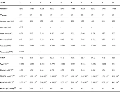
Page | xvi Table 2.1 – Conditions used for the homopolymerisation of NAM and HEA (targeted DPn of 10 and 100). RAFT polymerisations were conducted over 24 h in H2O/dioxane at 25 °C using redox initiation with TBHP/AsAc; [TBHP]0:[AsAc]0 = 1:0.5; [M]0 = 3.0 mol.L
-1 . Monomer conversion is > 99 % in all cases as determined by 1H NMR. ... 28
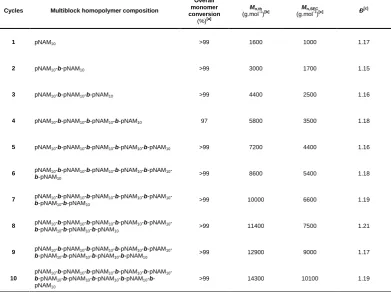
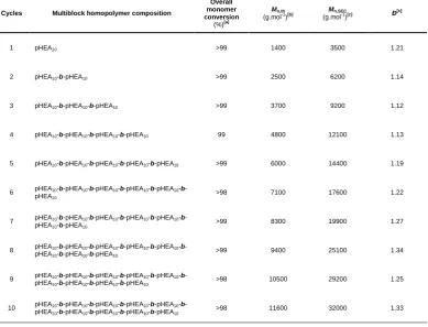
Table 2.2 – Summary of multiblock polymers prepared via sequential addition redox initiated aqueous RAFT polymerisation. ... 30
Table 2.3 – Monomer conversion and THF-SEC results for each block synthesis of (pNAM10)10 prepared via RAFT in H2O/dioxane at 25 °C using redox initiation with TBHP/AsAc. ... 54
Table 2.4 – Monomer conversion and THF-SEC results for each block synthesis of (pNAM10)10 prepared via RAFT in H2O/dioxane at 70 °C using VA-044 as thermal azoinitiator. ... 55
Table 2.5 – Monomer conversion and DMF-SEC results for each block synthesis of (pHEA10)10 prepared via RAFT in H2O/dioxane at 25 °C using redox initiation with TBHP/AsAc. ... 56
Table 2.6 – Monomer conversion and DMF-SEC results for each block synthesis of (pHEA10)10 prepared via RAFT in H2O/dioxane at 70 °C using VA-044 as thermal azoinitiator. ... 57
Table 2.7 – Monomer conversion and DMF-SEC results for each block synthesis of (pNAM100)6 prepared via RAFT in H2O/dioxane at 25 °C using redox initiation with TBHP/AsAc. ... 58
Table 2.8 – Monomer conversion and DMF-SEC results for each block synthesis of (pHEA100)4 prepared via RAFT in H2O/dioxane at 25 °C using redox initiation with TBHP/AsAc. ... 58
Page | xvii the acrylamide-based pentablock copolymer (DPn 100 per block) via RAFT in H2O/dioxane at 25 °C using redox initiation with TBHP/AsAc. ... 59
Table 2.11 – Monomer conversion and DMF-SEC results for each block synthesis of the acrylate-based heptablock copolymer (DPn ≤ 10 per block) via RAFT in H2O/dioxane at 25 °C using redox initiation with TBHP/AsAc. ... 60
Table 2.12 – Monomer conversion and DMF-SEC results for each block synthesis of the acrylate-based octablock copolymer (DPn ≤ 10 per block) via RAFT in H2O/dioxane at 25 °C using redox initiation with TBHP/AsAc. ... 61
Table 2.13 – Monomer conversion and DMF-SEC results for each block synthesis of the acrylate/acrylamide-based heptablock copolymer (DPn ≤ 10 per block) via RAFT in
H2O/dioxane at 25 °C using redox initiation with TBHP/AsAc. ... 62
Table 2.14 – Conditions used in preparation of (pNAM10)10via RAFT in H2O/dioxane at 25 °C using redox initiation with TBHP/AsAc. ... 63
Table 2.15 – Conditions used in preparation of (pNAM10)10via RAFT in H2O/dioxane at 70 °C using VA-044 as thermal azoinitiator. ... 64
Table 2.16 – Conditions used in preparation of (pHEA10)10 via RAFT in H2O/dioxane at 25 °C using redox initiation with TBHP/AsAc. ... 65
Table 2.17 – Conditions used in preparation of (pHEA10)10 via RAFT in H2O/dioxane at 70 °C using VA-044 as thermal azoinitiator. ... 66
Table 2.18 – Conditions used in preparation of (pNAM100)6via RAFT in H2O/dioxane at 25 °C using redox initiation with TBHP/AsAc. ... 67
Table 2.19 – Conditions used in preparation of (pHEA100)4 via RAFT in H2O/dioxane at 25 °C using redox initiation with TBHP/AsAc. ... 68
Page | xviii copolymer (DPn 100 per block) via RAFT in H2O/dioxane at 25 °C using redox initiation with TBHP/AsAc. ... 70
Table 2.22 – Conditions used in preparation of acrylate-based heptablock copolymer (DPn ≤ 10 per block) via RAFT in H2O/dioxane at 25 °C using redox initiation with TBHP/AsAc. ... 71
Table 2.23 – Conditions used in preparation of acrylate-based octablock copolymer (DPn ≤ 10 per block) via RAFT in H2O/dioxane at 25 °C using redox initiation with TBHP/AsAc. ... 72
Table 2.24 – Conditions used in preparation of acrylate/acrylamide-based heptablock copolymer (DPn ≤ 10 per block) via RAFT in H2O/dioxane at 25 °C using redox initiation with TBHP/AsAc. ... 73
Table 3.1 – Summary of NAM polymerisations via redox initiated aqueous RAFT polymerisation in H2O:dioxane (90:10) at 30 °C using different redox pairs and oxidising agent/reducing agent stoichiometry. [NAM]0 = 3.0 mol.L
-1
, [Oxidising agent]0 = 7.5 × 10 -4
mol.L-1. ... 81
Table 3.2 – Impact of experimental set-up (deoxygenation with N2, stirring, reaction vessel and open/closed system) on the redox-initiated RAFT polymerisation of poly(NAM) in H2O:dioxane (90:10) at 30 °C (24 h) using the redox couple TBHP/Brug7. [NAM]0 = 3.0 mol.L-1, [TBHP]0 = 5.0 × 10
-4
mol.L-1, [TBHP]0/[Brug7]0 = 1:0.5. Polymerisations were left for 24 h. ... 91
Table 4.1 – Summary of homo- and co-polymers prepared via RAFT used in this work. ... 110
Table 4.2 – Summary of conditions used in the preparation of homopolymers and statistical copolymers. ... 139
Table 4.3 – Summary of conditions used in the preparation of pDMA-co-pGEA copolymers. ... 140
Page | xix obtained after each step in the one-pot sequential addition polymerisation of diblock and tetrablock copolymers. ... 142
Table 4.6 – Fluorescence correction factor used for compensating discrepancies in the intrinsic fluorescence of each polymer (or peptide) during cell-uptake measurements. Values for fluorescein were obtained using fluorescein cadaverine (5 µM) and 16 h of incubation. ... 143
Table 4.7 – Percentage of compound internalised via passive uptake, as determined by the ratio of compound internalised at 4 °C versus 37 °C. Values were calculated using the data obtained at 2 h of incubation in MDA-231 and Caco2 cells. ... 144
Table 5.1 – Summary of PDMS-b-pBEA diblock copolymers prepared via RAFT polymerisation with the PDMS-PBTC mCTA. ... 163
Table 5.2 – Theoretical molar mass of PDMS-glycopolymers assuming full substitution. Dh and PDi determined using DLS. The dn/dc was determined using a defractometer and was used to calculate Ma and Nagg from SLS data. ... 170
Page | xx Scheme 1.1 – The RAFT Mechanism ... 3
Scheme 1.2 – Structures of various Z-groups used in RAFT polymerisation; addition rates decrease and fragmentation rates increase from left to right. * are used to highlight the activated (pyridinium) and deactivated (pyridine) forms of a switchable N-methyl-N -(4-pyridinyl) dithiocarbamate RAFT agent. ... 7
Scheme 1.3 – Structures of various R- groups used in RAFT polymerisation; the homolytic leaving group ability (kβ) decreases from left to right. ... 8
Scheme 1.4 – Generalised approaches for preparing block copolymers; 1) Sequential polymerisation; 2) Coupling of two pre-synthesised polymer chains; 3) Combination of polymerisation techniques in sequence. ... 10
Scheme 2.1 – Structures of reagents used in this work. Full abbreviations are in materials section (2.4.1). ... 27
Scheme 2.2 – Strategy for one-pot synthesis of multiblock copolymers via RAFT in H2O/dioxane at 25 °C using redox initiation with TBHP/AsAc. The synthesis of pHEA10-b -pAA10-b-pPEGA5-b-pMA10-b-pNAM10-b-pNIPAM10-b-pDMA10 is used as an example. .... 38
Scheme 3.1 – Structures of chain transfer agent, monomer, oxidising agents and reducing agents used in this work and reaction scheme for the aqueous redox-initiated RAFT polymerisation of NAM in H2O:dioxane (90:10) at 30 °C. ... 79
Scheme 4.1 – Synthesis of GEAdiBOC monomer; i) DCM, 3 h. ii) TEA, DCM, < 10 °C, 16 h. Synthesis of pGEAdiBOC via RAFT polymerisation; iii) VA-044, 1,4-dioxane/H2O, 45 °C, 7 h. iv) Deprotection of pGEAdiBOC; iv) TFA/TIPS/H2O, RT, 3 h. Dye attachment to RAFT polymer; 5-FITC cadaverine, HCTU, NMM, DMF, overnight. Dye attachment to polyArginine peptides prepared by SPPS; 5(6)-carboxyfluorescein, HCTU, NMM, DMF. 109
Scheme 4.2 – Synthesis of pDMA10-b-pGEA10-b-pDMA10-b-pGEA10 tetrablock copolymer via one-pot sequential addition RAFT polymerisation. ... 119
Page | xxi
AA Acrylic acid
ACVA 4,4’Azobis(4-cyanovaleric acid)
AFM Atomic force microscopy
AIBN 2,2’-Azobis(2-methylpropionitrile)
APS Ammonium persulfate
AROP Anionic ring opening polymerisation
AsAc Ascorbic acid (reducing agent)
BEA 2-Bromoethyl acrylate
BOC tert-butoxycarbonyl
Brug7 Brüggolit FF7
CEA 2-Carboxyethyl acrylate
CFP Cyan fluorescent protein
Con A Concanavalin A
CPP Cell-penetrating peptide
CTA Chain transfer agent
Đ Molar mass dispersity (Mw/Mn)
D2O Deuterium oxide
D3 Hexamethyl(cyclotrisiloxane)
DCM Dichloromethane
DEA N,N-diethylacrylamide
DEGMA Diethylene glycol methacrylate
Dh Hydrodynamic diameter
DIPEA N-Ethyldiisopropylamine
Page | xxii DMAdiblock p(DMA20)-b-p(GEA20)
DMAP 4-(Dimethylamino)pyridine
DMAstat p(DMA20)-st-p(GEA20)
DMAtetra p(DMA10)-b-p(GEA10)-b-p(DMA10)-b-p(GEA10)
DMEM Dulbecco's modified eagle medium
DMF N,N-Dimethylformamide
DMSO Dimethyl sulfoxide
dn/dc Refractive index increment
DPn Degree of polymerisation
DRI Differential refractive index
DSC Differential scanning calorimetry
E. coli Escherichia coli
EDCI N-(3-dimethylaminopropyl)-N’-ethylcarbodiimide
hydrochloride
EGMEA Ethylene glycol methyl ether acrylate
ESI Electrospray ionisation (mass spectroscopy)
Et2O Diethyl ether
GalEA (1-thio-β-D-galactose)ethyl acrylate
GEA Guanidine-ethyl acrylamide
GEAdiBOC di-BOC-protected guanidine ethyl acrylamide
GEAm Glucosyloxyethyl acrylamide
GEMA Glucosyloxyethyl methacrylate
GFP Green fluorescent protein
Page | xxiii
HCTU O-(1H-6-Chlorobenzotriazole-1-yl)-1,1,3,3-tetramethyluronium
hexafluorophosphate
HEA 2-Hydroxyethyl acrylate
HEAm N-Hydroxyethyl acrylamide
HEAmdiblock p(HEAm20)-b-p(GEA20)
HEAmstat p(HEAm20)-st-p(GEA20)
HEAmtetra p(HEAm10)-b-p(GEA10)-b-p(HEAm10)-b-p(GEA10)
HFIP 1,1,1,3,3,3-Hexafluoro-2-propanol
HPLC High performance liquid chromatography
HSCQ NMR Heteronuclear single quantum correlation spectroscopy
LAM Less activated monomer
LCST Lower critical solution temperature
LRP Controlled/”living” radical polymerisation
LS Light scattering
MA Methyl acrylate
Ma Average apparent molar mass
MADIX Macromolecular design via the interchange of xanthates
MALDI Matrix-assisted laser desorption/ionisation (mass spectroscopy)
MAM More activated monomer
MeOH Methanol
MLRP Metal-mediated living radical polymerisation
Mn Number-average molar mass
Nagg Aggregation number
Page | xxiv
NMM 4-Methylmorpholine
NMP N-Methyl-2-pyrrolidone
NMR Nuclear magnetic resonance spectroscopy
NVP N-vinylpyrrolidone
ox/red Oxidising agent/reducing agent stoichiometry
P1 PDMS60-b-pBEA6
P1Gal PDMS60-b-pGalEA6
P1Glu PDMS60-b-pGluEA6
P2 PDMS60-b-pBEA16
P2Gal PDMS60-b-pGalEA16
P2Glu PDMS60-b-pGluEA16
PABTC (propanoic acid)yl butyl trithiocarbonate
PB Phosphate buffer
PBS Phosphate buffered saline
PdI Polydispersity Index
PDMS poly(dimethylsiloxane)
PEG poly(ethylene glycol)
PEGA poly(ethylene glycol) methyl ether acrylate (average Mn 480 =
g.mol-1)
PET-RAFT Photoinduced electron transfer RAFT polymerisation
PMMA poly(methyl methacrylate)
PMOXA poly(2-methyloxazoline)
PMS N-methyl dibenzopyrazine methyl sulfate
Page | xxv
R9 polyArginine peptide comprised of 9 arginine residues
RAFT Reversible addition-fragmentation chain transfer
RDRP Reversible deactivation radical polymerisation
RME Receptor-mediated endocytosis
SEC Size exclusion chromatography
SFS Sodium formaldehyde sulfoxylate
SLS Static light scattering
SPPS Solid phase peptide synthesis
TBHP tert-butyl hydroperoxide
Tc Cold crystallisation transition temperature
TEM Transmission electron microscopy
TFA Trifluoroacetic acid
Tg Glass transition temperature
THF Tetrahydrofuran
TIPS Triisopropylsilane
Tm Melting transition temperature
V-601 Dimethyl 2,2’-azobis(2-methylpropionate)
VA-044 2,2′-Azobis[2-(2-imidazolin-2-yl)propane] dihydrochloride
VAc Vinyl acetate
VS Viscometry
Page | xxvi I’ve been fortunate enough to receive an enormous amount of support from many
amazing people during my time at Warwick and it would be pertinent for me to try and acknowledge them all here.
Firstly I would like to thank my supervisor Professor Sébastien Perrier for giving me the opportunity to undertake my studies at Warwick. I was actually in the process of applying to join him for a PhD in the sunny climes of Sydney when he announced that he was moving to Warwick, told me I should join him there instead, and the rest, as they say, is history. That small, crushing blow aside, I’ve really enjoyed having you as my boss. You’ve
had a fair amount of patience and given me plenty of guidance over the last four years, and allowed me to pursue a range of research topics.
Next, so as not to upset the hierarchy, I’d like to thank all the postdocs I’ve had the
pleasure to work with over the years. Firstly, I’d like to thank Dr Guillaume Gody for teaching me the subtle mysteries of RAFT polymerisation, and for all the supervision and collaboration during the early stages of the group. Thanks to Dr Johannes Brendel, you were always happy to chat away about chemistry-related things while I stood there and nodded like I understood what you were saying. You were always willing to advise me in my work but more importantly you’re just a really good guy and a friend. Next I’d like to thank Dr Matthias Hartlieb and Dr Raoul Peltier for being such great co-workers and friends over the last 18 months. In addition I’d like to thank you for all the good times we’ve had outside of work, letting me see Alfie and Abigail (and Karolin and Eloise) frequently, and for always letting me and/or Agnès lose at board games. A big thank you to Dr Joaquin (Ximo) Sanchis Martinez who has been a really important influence over the years, giving me more life advice than I could ever use, and also for buying me food. There are plenty of others who I would like to thank, including Kristian Kempe, Ming Koh Paul Wilson, Ed Mansfield, and Ahmed Eissa (Doctors all), for the various roles they have played during my PhD. Finally I’ll mention Dr Sylvain Catrouillet, for being amusingly French and for always trying his
hardest at football to no avail.
To (Dr) Zhang, Tammie and Sophie, with whom I have shared the entirety of this journey, I want to say thank you and well done. Junliang, it’s been a pleasure to work so
Page | xxvii items around just when I’m in a good working flow. I’d also like to give a special mention to
Alex Cook, for all the travelling we’ve done together and all the alcohol we’ve consumed, Julia Rho, because she’s a really nice person but more importantly an insanely good cook, and Majda Akrach, for the small arguments we’ve had regularly over the last two years, a strong character indeed, and one I’ll miss. Then there all the other people across the Perrier and Haddleton groups I’ve had the pleasure to share the corridor with, including Richard
Whitfield, Nuttapol Risangud, Guillaume Moriceau, Joji Tanaka, Caroline Bray, Dr Carlos Sanchez-Cano, Andy Kerr, Andy Lunn and Sean Ellacott. I’d also like to separately thank Pratik Gurnani for working with me on the PDMS project, and teaching me a few new techniques. Dr Alex Simula, who left the corridor 18 months ago and under normal circumstances I would have completely forgotten by now, remains a close friend and has continued to offer wise council when I need it, and also cheap holidays to Spain, for which I would like to thank him. Sophie, you’ve been a wonderful part of my time at Warwick.
Remarkably, we have been able to happily coexist as housemates for over three years. I really can’t remember us ever falling out, and while I’m pretty sure it’s mostly due to my chilled demeanour, I’m grateful you never made things anything but pleasant. I think I’m going to especially miss all the great times we spent together eating Julia’s delicious baked
goods. We’ve been truly spoiled.
I’d quickly like to thank Bagel and Mario. I think most people who know me aren’t
surprised to find my dogs mentioned in the acknowledgments such is my love for them. They have of course in no way helped me with my academic endeavours, but they give life an additional quality that really can’t be understated. They’re good boys.
Agnès, you have been such a vital part of my final year here and I’m so lucky that you decided to come back to Warwick for your PhD. So many of my favourite memories from my time here I owe to you, and through the ordeal of writing up you have repeatedly given me the reassurance I so needed. You’ve been so devoted to my cause. I can’t thank you enough, I can only try and return the favour when it’s your turn. You made it in below
Mario, in case you didn’t notice.
Finally, I’d like to thank my family. I’ll begin with by saying thanks to my Gran, for
Page | xxviii people I wish to acknowledge are my parents. You have given me nothing but support throughout my life, I don’t really have the right words to express my gratitude. But thank you. Dad, I haven’t had to call on your guidance too much over the course of this PhD, but when I have you’ve always been there to provide it in such a way that I can come to my own
decision, which I have really appreciated. And to my Mum, who has been the most important influence in my life. It’s so reassuring to know that I can come home whenever I want, knowing you’ll be there, and knowing you’ll be happy to see me. Dom has said before that he doesn’t know of anybody as inherently good and selfless as you (he obviously didn’t use the word “inherently”, but still), and I can only agree with him. I don’t even think I’m being
Page | xxix Experimental work contained in this thesis is original research carried out by the author, unless stated otherwise, in the Department of Chemistry at the University of Warwick, between October 2013 and August 2017. No material contained here has been submitted for any other degree, or at any other institution.
The work presented was carried out by the author with the following exceptions:
Chapter 4: XTT assays, cell uptake studies and fluorescence corrections were performed by Dr. Raoul Peltier (University of Warwick. School of Life Science)
Chapter 5: Confocal microscopy of GGP – E. coli interactions were performed by Dr. Ahmed Eissa (University of Warwick, School of Engineering)
Date: ___________________ ____________________
Page | xxx Publications by the author arising from work in this thesis:
Chapter 2
“Preparation of complex multiblock copolymers via RAFT polymerization at room temperature”
L. Martin, G. Gody and S. Perrier Polym. Chem., 2015, 6, 4875-4886
Chapter 3
“On the Use of Redox initiation in aqueous RAFT polymerisation”
L. Martin, G. Gody and S. Perrier In preparation
Chapter 4
“Investigating the Cell-Uptake of Guanidinium-Rich RAFT (co)Polymers: Impact of
Comonomer and Monomer Distribution”
L. Martin, A. Kuroki, J. Town, R. Peltier and S. Perrier In Preparation
Chapter 5
“Flexible Giant Glycosylated Polymersomes with Tuneable Behaviour Towards
Bacteria”
Page | 1
Chapter 1
– Introduction
– Block Copolymers
1.1
Block copolymers may be described as polymeric chains comprising two (or more) distinct chemical compositions, each occupying discreet regions along the backbone. Such defined segregation of chemical functionality may impart highly desirable properties in the final polymeric material, prompting ever-increasing levels of interest in both academic research and industry.1 A key advantageous property of block copolymers is the ability to undergo nanoscale self-assembly by virtue of contrasting natures of different polymer segments. In bulk phase and thin films, immiscibility of the polymer blocks can result in microphase separation, generating a range of novel morphologies such as body-centered-cubic spheres, bicontinuous gyroids, hexagonal cylinders or lamellae (for AB diblock copolymer systems), with the nature of the self-assembly influenced by block copolymer composition and processing methods.2-5 This microphase separation behaviour is exploited for a wide range of applications including electronics,6 photovoltaics,7 various membrane technologies8-10 and thermoplastic elastomers.11, 12 Meanwhile, in solution, block copolymers may self-assemble into a range of well-defined nanostructures when the solvent is selective for a certain block, generating morphologies such as micelles, vesicles and worm-like micelles.2, 13-18 These high-potential materials are intensely studied for advanced technology applications such as drug delivery19-23 and nanoreactors.24-26
The typical synthetic approach for the preparation of block copolymers is via sequential chain growth polymerisations of different monomers. In order to achieve this the initial (well-defined) polymer block must remain active for the polymerisation of the second monomer (i.e. a living polymerisation process). The synthesis of block copolymers was first demonstrated by Szwarc in 1956, using anionic polymerisation.27, 28 With this living polymerisation technique, polymer chains would grow in unison until all the monomer was exhausted, but would then continue to grow upon the addition of a second batch of monomer. When the second batch of monomer was different to the first, block copolymers were obtained. Sometime later, the successful synthesis of block copolymers was demonstrated with other living polymerisation techniques such as cationic polymerisation.29, 30
Page | 2
– Reversible Deactivation Radical Polymerisation (RDRP)
1.2
The emergence of reversible deactivation radical polymerisation (RDRP) techniques, also known as controlled/living radical polymerisation (LRP) has greatly expanded the scope of achievable polymeric compositions and architectures.31 These approaches are typically applicable to a greater range of chemical functionalities and more tolerant towards the presence of impurities than ionic techniques, making them more versatile and robust. Although not truly living polymerisations (termination events will occur throughout the polymerisation), RDRP techniques such as nitroxide-mediated polymerisation (NMP),32-34 metal-mediated living radical polymerisation (MLRP)35-39 and reversible addition-fragmentation chain transfer (RAFT)40-43 polymerisation are considered to possess living character insofar that; the molar mass obtained increases linearly with monomer conversion (in a pre-determined fashion); narrow molar mass distributions may be obtained; ω-chain end is retained and may be re-activated towards the addition of further monomer. These characteristics are achieved in RDRP methods through the establishment of an equilibrium between a low fraction of active chains and a high fraction of dormant chains, in a fashion which provides all chains with an equal probability to grow, at a uniform rate.
– RAFT Polymerisation
1.3
Reversible addition fragmentation chain transfer (RAFT) polymerisation was first reported in 1998 by Moad, Rizzardo, Thang and co-workers and over the following (almost) two decades has become established as one of the most powerful techniques for preparation of functional polymeric architectures.40, 42, 43 Independently, Zard and co-workers reported the synthesis of “living” polymers via radical addition to a xanthate, coining the technique
macromolecular design via the interchange of xanthates (MADIX).44, 45 Importantly, the “living character” that this process confers may be exploited for the preparation of block
Page | 3 and ionic liquids,40, 46-49 at temperatures ranging from - 15 °C to 180 °C,50-52 and also at high pressures.53 Control over polymer molar mass and molar mass distribution in a degenerative chain transfer process is achieved by establishing a rapid equilibrium between active and dormant chains in a fashion which provides all polymer chains with an equal opportunity to propagate. In RAFT, this equilibrium is achieved through the rapid exchange of a thiocarbonylthio moiety between growing chains.
1.3.1 – The mechanism of RAFT
As with a conventional radical polymerisation process, RAFT polymerisation begins with radical generation and initiation. An initiator-derived radical (I•) (traditionally generated through an exogenous radical source) will add to a monomer (M) (ki) which upon propagation generates a polymeric radical species Pn•, which will continue to propagate (kp). In the presence of a chain transfer agent (1), Pn• may also add to the reactive C=S bond (kadd) to create an intermediate radical species (2) which will fragment either back towards the starting materials (k-add) or, preferably, towards a macro-CTA (3) and a CTA-derived radical
Page | 4 species R• (kβ), in a step known as the pre-equilibrium. R• may re-initiate polymerisation by adding to monomer (kiR) to give another active polymeric radical species Pm•. Once all of the CTA (1) is consumed and macro-CTAs (3) are the sole thiocarbonylthio species present, the system enters a main equilibrium whereby the active radical centre (which may propagate, kp) is rapidly exchanged (kaddP, k-addP) between polymer chains via the intermediate radical 4. This reversible addition-fragmentation equilibrium provides chains with an equal opportunity to grow, affording control over the molar mass distribution. Inevitably, as with conventional radical polymerisation, all radical species generated will terminate, principally through either combination (ktc) or disproportionation (ktd). However, considering the number of radical species generated is generally low relative to the number of CTAs, the majority of chains will possess the R-group at the α-chain end and the thiocarbonylthio RAFT end-group at the ω-chain end.
1.3.2 – Control of molar mass
Considering the general composition of a RAFT polymer, the average number of monomer units per polymer chain (degree of polymerisation, DPn) and therefore the
(number) average molar mass of the polymer (Mn) may be inferred from the ratio of consumed monomer to CTA, as shown in equations 1.1 and 1.2:
Where [M]0 is the initial monomer concentration; p is the monomer conversion; [CTA]0 is the initial concentration of CTA; n is the number of radicals generated by one initiating species (for example, an azoinitiator thermally decomposes to generate two initiating radicals, so n would equal 2); f is the initiator efficiency; [I]0 is the initial concentration of initiator; kd is the decomposition rate coefficient of the initiator; the term (1-fc/2) describes the average number of chains generated in a radical-radical termination event, where fc is the
DP𝑛=
M 0 . 𝑝
CTA 0 + n𝑓 I 0 1 − e−𝑘d𝑡 1 −𝑓2 c
𝑀n,th=
M 0 . 𝑝 . 𝑀M
CTA 0 + n𝑓 I 0 1 − e−𝑘d𝑡 1 −𝑓2 c
+ 𝑀CTA
1.1
Page | 5 coupling factor; MM and MCTA are the molar masses of the monomer CTA, respectively. Provided that the number of initiator-derived chains is negligible in comparison to CTA-derived chains the equations 1.1 and 1.2 may be simplified to equations 1.1b and 1.2b. However, while the ratio of CTA/monomer dictates the average molar mass of the resulting polymeric population, the nature of the CTA is crucial since this will influence how well-defined the population is in terms of molar mass distribution.
DP𝑛=
M 0 . 𝑝
CTA 0
𝑀n,th=
M 0 . 𝑝 . 𝑀M
CTA 0 + 𝑀CTA
1.1b
Page | 6
1.3.3 – Control of molar mass distribution
In order to ensure control over the molar mass distribution two principal criteria must be satisfied in the RAFT mechanism. Firstly, the pre-equilibrium step should proceed rapidly and quantitatively towards R• (which should then react efficiently with monomer). Secondly, exchange of radical centres between polymer chains should be rapid relative to the rate of propagation. These criteria may be met through careful consideration of the R- and Z- groups of the RAFT agent relative to the monomer of choice. The nature of the Z-group determines the reactivity of the C=S bond towards addition and fragmentation.54 For a well-controlled RAFT polymerisation, the rate at which the polymeric radicals add to the thiocarbonylthio moiety should be greater than the rate at which they propagate (kaddP >> kp), allowing chains to grow at a more uniform rate. The reactivity of a CTA is expressed in terms of its chain transfer coefficient (Ctr) which describes the relative rates of chain transfer (ktr) to propagation (kp), and is shown in equation 1.3:
The rate constant of transfer (ktr), which is described in equation 1.4, is dependent on the addition-fragmentation behaviour during the pre-equilibrium. The term ϕ, which is introduced in equation 1.5, describes the tendency for the pre-equilibrium to proceed towards the formation of R•. A number of different Z-group structures have been employed in RAFT polymerisation, such as dithioesters, trithiocarbonates, xanthates and dithiocarbamates.55, 56 The two latter examples are less reactive towards radical addition and are therefore better suited for the control of highly reactive propagating radicals, derived from monomers such as vinyl esters and vinyl amides.57, 58 Meanwhile, for less reactive propagating radicals, derived from monomers such as (meth)acrylates, (meth)acrylamides and styrenic derivatives, the more active CTAs such as dithioesters and trithiocarbonates are preferred to ensure Ctr is high.41, 59, 60 A range of Z-group structures are shown in Scheme 1.2, in order of their reactivity towards radical addition.
𝐶tr =
𝑘tr
𝑘p
𝑘tr= 𝜙𝑘add
1.3
Page | 7
Scheme 1.2 – Structures of various Z-groups used in RAFT polymerisation; addition rates
decrease and fragmentation rates increase from left to right. * are used to highlight the activated
(pyridinium) and deactivated (pyridine) forms of a switchable N-methyl-N-(4-pyridinyl) dithiocarbamate
RAFT agent.
As previously stated, the pre-equilibrium step should proceed rapidly and to completion in order for main equilibrium to begin. This requires that fragmentation of the intermediate radical 2 proceeds preferentially towards the CTA-derived R-group radical R• (kβ) as opposed to the polymeric radical Pn• (k-add), and that this favoured R• radical may efficiently add with monomer (kiR > kp), thereby exiting the pre-equilibrium. The tendency for fragmentation of intermediate 2 towards R• is defined by the partition coefficient, ϕ, according to equation 1.5:
Where the rate constants are defined in Scheme 1.1. For the pre-equilibrium to proceed towards the desired products (R• and 3), ϕ should be ≥ 0.5 (kβ > k-add) which dictates that R• must be a better homolytic leaving group than Pn
•
. Radical stability, polarity and steric effects will impact the leaving group ability of R• relative to Pn• as well as its efficiency for adding to monomer, and therefore must be carefully considered with respect to the monomer used.61 Many different R-groups have been reported representing a spectrum of leaving group ability (Scheme 1.3).55, 56 The broad range of both R- and Z-group chemistries enables the behaviour of a RAFT agent to be readily tuned and it is this versatility that affords
>>
>
>
>
>
~
>>
~
>
~
~
>
*
*
𝜙 = 𝑘𝛽
𝑘−𝑎𝑑𝑑+ 𝑘𝛽
Page | 8 control over such an impressive range of monomer types compared to other RDRP approaches.
Scheme 1.3 – Structures of various R- groups used in RAFT polymerisation; the homolytic
leaving group ability (kβ) decreases from left to right.
Fortunately, the influence of the R- and Z- group in RAFT polymerisation has been extensively reviewed and general guidelines for selecting an appropriate RAFT agent based on monomer type are available.54-57, 61
– Synthesis of Block Copolymers
1.4
1.4.1 – Block copolymers
via
sequential RAFT polymerisations
For the successful preparation of block copolymers using a sequential polymerisation approach (in RDRP), it is essential that the majority of the polymer chains exist in a dormant state, which may be re-activated for the polymerisation of further monomer. In RAFT, these dormant (or “living”) chains are those which possess a thiocarbonylthio moiety at the ω
-chain end. A degenerative transfer mechanism such as RAFT does not itself add or remove radicals from the system, it merely mediates the exchange of the radical centre between different species. Therefore, radicals must be continually provided throughout the polymerisation, and all of these generated radicals must terminate at some point during the polymerisation. As such, there will be a certain proportion of chains which do not conform to the desired structure; α-chain ends derived from initiator and ω-chain ends which have undergone termination. These defective chain ends are interchangeable with those of the desired product, leading to a mixture of α,ω-functionality. While initiator-derived chains do not prohibit the addition of further monomer to produce a block copolymer, terminated chains cannot grow and therefore will remain as homopolymer impurities in the final block copolymer product. It is important to note that initiator-derived chains of the new monomer are also produced during a chain extension, giving another homopolymer impurity. The
~
~
>
>
>
Page | 9 proportion of dormant chains at the end of a polymerisation, referred to as the livingness, may be inferred from the amount of radicals introduced into the system over the course of the polymerisation relative to the amount of CTA present according to equation 1.6:
Where L is the number fraction of living chains, [CTA]0 is the initial concentration of chain transfer agent and nf[I]0(1-e
-kdt
)(1-fc/2) describes the concentration of radicals generated through decomposition of a thermal initiator. However, while a high proportion of living chains is essential for successful block copolymer synthesis, it is not the only consideration which must be made. Of course, the initial polymer block serves as a macro-CTA for polymerisation of the second monomer, and hence the requirements discussed previously regarding the nature of the Z- and R-groups still hold true. Fragmentation should tend towards the macro-R• which must be able to add to the new monomer. If this is not the case, and the newly formed initiator-derived macro-radicals are better homolytic groups than macro-R•, a significant amount of new homopolymer will be formed instead. Furthermore, the second monomer type must also be compatible with the Z-group, so as to ensure the sequential polymerisation proceeds in a controlled fashion. This represents an inherent restriction in terms of the types, and order, of monomers which may be used in a successful block copolymer synthesis (via a sequential polymerisation approach) and care should be taken when designing such syntheses.55, 62
However, the development of more versatile RAFT agents, which can control the
polymerisation of more activated monomers (MAMs) (i.e. (meth)acrylates,
(meth)acrylamides and styrenic derivatives) and less activated monomers (LAMs) (i.e. vinyl esters and vinyl amides) has gone some way to address issues related to Z-group compatibility. With switchable dithiocarbamate RAFT agents, the reactivity of the thiocarbonylthio group may be readily tuned towards MAMs or LAMs through the introduction of acid or base, respectively afford control.55, 63-66 Keddie and co-workers exploited the switchable reactivity of a N-methyl-N-(4-pyridinyl) dithiocarbamate RAFT agent to prepare well-defined (Đ < 1.3) poly(N,N-dimethylacrylamide)-block-poly(vinyl acetate) (p(DMA)-b-p(VAc)) diblock copolymers via sequential RAFT polymerisation.63
𝐿 = CTA 0
CTA 0 + n𝑓 I 0 1 − e−𝑘d𝑡 1 −𝑓2 c
Page | 10 Meanwhile, another class of dithiocarbamates, 3,5-dimethyl-1H-pyrazole-1-carbodithioates, have been demonstrated to afford control over the polymerisation of both MAMs and LAMs, and similarly p(DMA)-b-p(VAc) diblock copolymers could be successfully prepared.65 However, the polymerisation sequence is still restricted in such systems since a LAM-derived macro-R-groups is a poor homolytic leaving group in the polymerisation of
MAMs.62
1.4.2 – Alternative synthetic approaches to block copolymers
In instances where a sequential RAFT polymerisation approach is not appropriate for the synthesis of the desired block copolymer, such as those briefly discussed above, or when one of the monomers is not polymerisable via RAFT (or any radical polymerisation process), there are a number of alternative synthetic approaches which may be employed (Scheme 1.4). However, it should be noted that the following approaches, as with sequential polymerisation, apply (in principle) to all controlled polymerisation techniques.
Scheme 1.4 – Generalised approaches for preparing block copolymers; 1) Sequential polymerisation; 2) Coupling of two pre-synthesised polymer chains; 3) Combination of polymerisation techniques in sequence.
Page | 11 A range of efficient coupling chemistries, including amine-tertiary isocyanate coupling71 and hetero Diels-Alder coupling,72, 73 have been applied to RAFT-based polymers in this context.
Utilising different polymerisation techniques in succession is another interesting avenue towards block copolymers. Here, a polymer chain will be synthesised with one polymerisation process, whereby a chain end will possess (either pre- or post-polymerisation) the necessary functional group to mediate the controlled polymerisation of a second block using a second polymerisation technique (Scheme 1.4, approach 3).9 The macro-CTA approach entails the installation of a CTA at the end of a pre-synthesised, well-defined polymer, from which RAFT polymerisation of a second monomer may then be conducted.55, 74 This approach has been used to prepare RAFT-functional block copolymers with initial blocks such as poly(ethylene glycol) (PEG)75-77 and poly(dimethylsiloxane) (PDMS),78 which cannot be prepared via radical-based polymerisation techniques.
– Multiblock Copolymers
1.5
Multiblock copolymers, which possess multiple distinct regions of chemical functionality along the polymer backbone, represent highly interesting materials. Considering the interesting properties and wide-ranging applications of relatively simple AB, ABA and ABC type block copolymers, increasing both the number and nature of chemically distinct blocks may lead to more complex self-assembly behaviour or materials with enhanced properties.79, 80 For example, Jackson and co-workers reported an ABAC terpolymer synthesised through a combination of (sequential) anionic polymerisation followed by ring-opening polymerisation to construct nanoporous membranes with enhanced mechanical stability.81, 82 However, in order to effectively explore the potential advantages of incorporating additional functional polymer blocks, more powerful and versatile synthetic strategies are required. RDRP techniques are promising candidates to fulfil this role considering their broad access to functionality, however in order to achieve such advanced control over polymer microstructure (in a practical fashion) these approaches must be extremely well-optimised.
Page | 12 polymerisations, the inevitable accumulation of dead polymer chains becomes non-negligible, often leading to a loss in molar mass control and broad molar mass distributions. In the preparation block copolymers, it is common practice to stop the first RAFT polymerisation cycle at moderate levels of monomer conversion (≤ 70 %) and remove the
leftover monomer before performing the next polymerisation. This is because achieving full monomer conversion in radical polymerisation requires a far greater number of radicals; the rate of polymerisation decreases over the course of polymerisation as both monomer and initiator are depleted and termination events become more prevalent by comparison. Multiblock copolymers have been prepared via RAFT using such an approach, however it may be considered a time- and resource-costly process, and moreover the final multiblock copolymers prepared were not well-controlled by most standards.83, 84 For instance, Hadjiantoniou and co-workers reported the synthesis of an ABABA pentablock copolymer by sequential RAFT polymerisations, with each step requiring 15 – 20 h of polymerisation and 2 days of purification, for a final dispersity of 1.83.83
In recent years, development in the implementation of RDRP techniques have enabled polymerisations to proceed towards full monomer conversion with unprecedentedly high chain-end fidelity and narrow molar mass distributions. This feature has been exploited in both Cu(0)-mediated and RAFT polymerisation for the preparation of multiblock copolymers in one-pot, without the need for purification steps in between each block synthesis.85-93
1.5.1 – Multiblock copolymers
via
RAFT
Page | 13 Where kp and kt are the rate constant of propagation and termination, respectively; kd is the rate constant of decomposition for a thermal initiator; [M] and [P•] are the concentrations of monomer and active radical species, respectively; f is the initiator efficiency and [I]0e
-kdt is the initiator concentration remaining at time t. The use of acrylamide monomers which possesses an intrinsically high value of kp/(kt)1/2,95 water as a solvent (which increases the kp of these monomers),96 and high monomer concentrations were instrumental in achieving high rates of polymerisation (and near-quantitative monomer conversion) with extremely low concentrations of initiator. Importantly, it was demonstrated how that the degree of polymerisation targeted will influence the number of sequential polymerisations which can be successfully conducted whilst maintaining control over the molar mass and molar mass distribution. Since the ratio [M]:[I] dictates the rate of polymerisation (and monomer conversion) (Rp ∝ [M]/[I], equation 1.7), [CTA]:[I] dictates the livingness (L ∝ [CTA]/[I],
equation 1.6), and [M]:[CTA] dictates the degree of polymerisation (DPn ∝ [M]/[CTA],
equation 1.1) it follows that in decreasing DPn, livingness will increase. Of course, since
RAFT polymerisation (and all other chain growth-polymerisation methods) leads to a molar mass distribution (however narrow) there is an inherent limitation as to the minimum DPn
which may be targeted to ensure the majority of chains possess the correct block sequence.97
The refined approach established by Gody and co-workers was an extremely important proof of concept, demonstrating the potential of RAFT polymerisation for the preparation of complex multiblock copolymers in a convenient and timely fashion. However, the collective avenues of optimisation which made this approach powerful (acrylamide monomers, water as solvent, high temperatures, targeting low degrees of polymerisation) also represent a series of design limitations, which restricts the range of applications multiblock copolymers made via this approach can be utilised for. In order to access further functionality for the study of block copolymers in specific applications, a compromise on the extent to which the synthetic approach is optimised may be necessary.
𝑅p= 𝑘p M P• = 𝑘p M
𝑓𝑘d I 0𝑒−𝑘d𝑡
𝑘t
𝑅t= 2𝑘t P• 2= 2𝑓𝑘d 𝐼 0𝑒−𝑘d𝑡
1.7