Relational Reinforcement Learning with
Continuous Actions by Combining Behavioural
Cloning and Locally Weighted Regression
Julio H. Zaragoza, Eduardo F. Morales
National Institute of Astrophysics, Optics and Electronics, Computer Science Department, Tonantzintla, México. Email: {jzaragoza, emorales}@inaoep.mx
Received October 30th, 2009; revised January 10th, 2010; accepted January 30th, 2010.
ABSTRACT
Reinforcement Learning is a commonly used technique for learning tasks in robotics, however, traditional algorithms are unable to handle large amounts of data coming from the robot’s sensors, require long training times, and use dis-crete actions. This work introduces TS-RRLCA, a two stage method to tackle these problems. In the first stage, low-level data coming from the robot’s sensors is transformed into a more natural, relational representation based on rooms, walls, corners, doors and obstacles, significantly reducing the state space. We use this representation along with Be-havioural Cloning, i.e., traces provided by the user; to learn, in few iterations, a relational control policy with discrete actions which can be re-used in different environments. In the second stage, we use Locally Weighted Regression to transform the initial policy into a continuous actions policy. We tested our approach in simulation and with a real ser-vice robot on different environments for different navigation and following tasks. Results show how the policies can be used on different domains and perform smoother, faster and shorter paths than the original discrete actions policies.
Keywords: Relational Reinforcement Learning, Behavioural Cloning, Continuous Actions, Robotics
1. Introduction
Nowadays it is possible to find service robots for many different tasks like entertainment, assistance, maintenance, cleanse, transport, guidance, etc. Due to the wide range of services that they provide, the incorporation of service robots in places like houses and offices has increased in recent years. Their complete incorporation and accep-tance, however, will depend on their capability to learn new tasks. Unfortunately, programming service robots for learning new tasks is a complex, specialized and time consuming process.
An alternative and more attractive approach is to show the robot how to perform a task, rather than trying to program it, and let the robot to learn the fine details of how to perform the task. This is the approach that we follow on this paper.
Reinforcement Learning (RL) [1] has been widely used and suggested as a good candidate for learning tasks in robotics, e.g., [2-9]. This is mainly because it allows an agent, i.e., the robot, to “autonomously” develop a con-trol policy for performing a new task while interacting with its environment. The robot only needs to know the
goal of the task, i.e., the final state, and a set of possible actions associated with each state.
The use and application of traditional RL techniques however, has been hampered by four main aspects: 1) vast amount of data produced by the robot’s sensors, 2) large search spaces, 3) the use of discrete actions, and 4) the inability to re-use previously learned policies in new, although related, tasks.
Robots are normally equipped with laser range sensors, rings of sonars, cameras, etc., all of which produce a large number of readings at high sample rates creating problems to many machine learning algorithms.
com-putationally expensive. Also, in many approaches, once a policy has been learned to solve a particular task, it can-not be re-used on similar tasks.
In this paper, TS-RRLCA (Two-Stage Relational Rein- forcement Learning with Continuous Actions), a two- stage method that tackles these problems, is presented. In the first stage, low-level information from the robot’s sensors is transformed into a relational representation to characterize a set of states describing the robot’s envi-ronment. With these relational states we applied a variant of the Q-learning algorithm to develop a relational policy with discrete actions. It is shown how the policies learned with this representation framework are transferable to other similar domains without further learning. We also use Behavioural Cloning [10], i.e., human traces of the task, to consider only a subset of the possible actions per state, accelerating the policy learning process and ob-taining a relational control policy with discrete actions in a few iterations. In the second stage, the learned policy is transformed into a relational policy with continuous ac-tions through a fast Locally Weighted Regression (LWR) process.
The learned policies were successfully applied to a simulated and a real service robot for navigation and fol-lowing tasks with different scenarios and goals. Results show that the continuous actions policies are able to produce smoother, shorter, faster and more similar paths to those produced by humans than the original relational discrete actions policies.
This paper is organized as follows. Section 2 describes related work. Section 3 introduces a process to reduce the data coming from the robot’s sensors. Section 4 describes our relational representation to characterize states and actions. Sections 5 and 6 describe, respectively, the first and second stages of the proposed method. Section 7 shows experiments and results, Section 8 presents some discussion about our method and the experimental results, and Section 9 concludes and suggests future research directions.
2. Related Work
There is a vast amount of literature describing RL tech-niques in robotics. In this section we only review the most closely related work to our proposal.
In [8] a method to build relational macros for transfer learning in robot’s navigation tasks is introduced. A macro consists of a finite state machine, i.e., a set of nodes along with rulesets for transitions and action choices. In [11], a proposal to learn relational decision trees as abstract navigation strategies from example paths in presented. These two approaches use relational repre-sentations to transfer learned knowledge and use training examples to speed up learning, however, they only con-sider discrete actions.
In [9], the authors introduced a method that temporar-ily drives a robot which follows certain initial policy while some user commands play the role of training input to the learning component, which optimizes the autono-mous control policy for the current task. In [2], a robot is tele-operated to learn sequences of state-action pairs that show how to perform a task. These methods reduce the computational costs and times for developing its control scheme, but they use discrete actions and are unable to transfer learned knowledge.
An alternative to represent continuous actions is to ap-proximate a continuous function over the state space. The work developed in [12] is a Neural Network coupled with an interpolation technique that approximates Q- values to find a continuous function over all the search space. In [13], the authors use Gaussian Processes for learning a probabilistic distribution for a robot navigation problem. The main drawback of these methods is the computational costs and the long training times as they try to generate a continuous function over all of the search space.
Our method learns, through a relational representation, relational discrete actions policies able to transfer know- ledge between similar domains. We also speed up and simplify the learning process by using traces provided by the user. Finally we use a fast LWR to transform the original discrete actions policy into a continuous actions policy. In the following sections we describe in detail the proposed method.
3. Natural Landmarks Representation
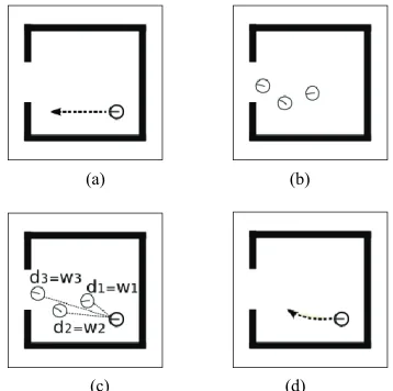
A robot senses and returns large amounts of data read-ings coming from its sensors while performing a task. In order to produce a smaller set of meaningful information TS-RRLCA uses a process based on [14,15] In [14] the authors described a process able to identify three kinds of natural landmarks through laser sensor readings: 1) dis-continuities, defined as an abrupt variation in the meas-ured distance of two consecutive laser readings (Figure 1(a)), 2) walls, identified using the Hough transform (Figure 1(c)), and 3) corners, defined as the location where two walls intersect and form an angle (Figure 1(d)). We also add obstacles identified through sonars and defined as any detected object within certain range (Figure 1(e)).
(a) (b) (c)
[image:3.595.61.286.91.267.2]
(d) (e)
Figure 1. Natural landmarks types and associated attributes, (a) discontinuity detection; (b) discontinuity Types; (c) wall detection; (d) corner detection; (e) wall detection
length (len), for all of the other landmarks the A attribute is not used.
[image:3.595.309.534.93.178.2]In [15] the data from laser readings is used to feed a clustering-based process which is able to identify the robot’s actual location such as room, corridor and/or in-tersection (the location where rooms and corridors meet).
Figure 2 shows examples of the resulting location classi-fication process.
Table 1 shows an example of the data after applying these processes to the laser and sonar readings from Fig-ure 3. The robot’s actual location in this case is in-room.
The natural landmarks along with the robot’s actual location are used to characterize the relational states that describe the environment.
4. Relational Representations for States and
Actions
A relational representation for states and actions has the advantage that it can produce relational policies that can be re-used in other, although similar, domains without any further learning. The idea it to represent states as sets of properties that can be used to characterize a particular situation which may be common to other states. For ex-ample, suppose the robot has some predicates that are able to recognize a room from its sensors’ readings. If the robot has learned a policy to exit a room, then it can ap-ply it to exit any recognizable room regardless of the current environment.
A relational state (r-state) is a conjunction of first or-der predicates. Our states are characterized by the fol-lowing predicates which receive as parameters a set of values such as those shown in Table 1.
1) place: This predicate returns the robot’s location, which can be in-room, in-door, in-corridor and in- intersection.
(a) (b) (c)
Figure 2. Locations detected through a clustering processes, (a) room; (b) intersection; (c) corridor
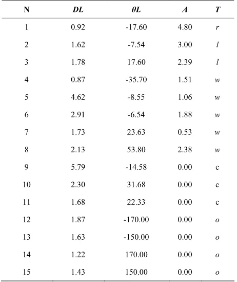
Table 1. Identified natural landmarks from the sensor’s readings from Figure 3
N DL θL A T
1 0.92 -17.60 4.80 r
2 1.62 -7.54 3.00 l
3 1.78 17.60 2.39 l
4 0.87 -35.70 1.51 w
5 4.62 -8.55 1.06 w
6 2.91 -6.54 1.88 w
7 1.73 23.63 0.53 w
8 2.13 53.80 2.38 w
9 5.79 -14.58 0.00 c
10 2.30 31.68 0.00 c
11 1.68 22.33 0.00 c
12 1.87 -170.00 0.00 o
13 1.63 -150.00 0.00 o
14 1.22 170.00 0.00 o
[image:3.595.307.539.255.683.2]15 1.43 150.00 0.00 o
[image:3.595.308.539.263.537.2]2) doors-detected: This predicate returns the orienta-tion and distance to doors. A door is characterized by identifying a right discontinuity (r) followed by a left discontinuity (l) from the natural landmarks. The door’s orientation angle and distance values are calculated by averaging the values of the right and left discontinuities angles and distances. The discretized values used for door orientation are: right (door’s angle between –67.5° and –112.5°), left (67.5° to 112.5°), front (22.5° to –22.5°), back (157.5° to –157.5°), right-back (–112.5° to –157.5°), right-front (–22.5° to –67.5°), left-back (112.5° to 157.5°) and left-front (22.5° to 67.5°). The discretized values used for distance are: hit (door’s distance between 0 m and 0.3 m), close (0.3 m to 1.5 m), near (1.5 m to 4.0 m) and far (door’s distance > 4.0 m).
For example, if the following discontinuities are ob-tained from the robot’s sensors (shown in Table 1: [0.92, –17.60, 4.80, r], [1.62, –7.54, 3.00, l]), the following predicate is produced:
doors-detected ([front, close, –12.57, 1.27])
This predicate corresponds to the orientation and dis-tance descriptions of a detected door (shown in Figure 3), and for every pair of right and left discontinuities a list with these orientation and distance descriptions is gener-ated.
3) walls-detected: This predicate returns the length, orientation and distance to walls (type w landmarks). Possible values for wall’s length are: small (length be-tween 0.15 m and 1.5 m), medium (1.5 m to 4.0 m) and
large (wall’s size or length > 4.0 m). The discrete values used for orientation and distance are the same as with doors and the same goes for predicates corners-detected
and obstacles-detected described below.
4) corners-detected: This predicate returns the orienta-tion and distance to corners (type c landmarks).
5) obstacles-detected: This predicate returns the orien-tation and distance to obstacles (type o landmarks).
6) goal-position: This predicate returns the relative ori-entation and distance between the robot and the current goal. Receives as parameter the robot’s current position and the goal’s current position, though a trigonometry process, the orientation and distance values are calcu-lated and then discretized as same as with doors.
7) goal-reached: This predicate indicates if the robot is in its goal position. Possible values are true or false.
The previous predicates tell the robot if it is in a room, a corridor or an intersection, detect walls, corners, doors, obstacles and corridors and give a rough estimate of the direction and distance to the goal. Analogous to r-states, r-actions are conjunctions of the following first order logic predicates that receive as parameters the odome-ter’s speed and angle readings.
8) go: This predicate returns the robot’s actual moving
action. Its possible values are front (speed > 0.1 m/s), nil
(–0.1 m/s < speed < 0.1 m/s) and back (speed < –0.1 m/s).
9) turn: This predicate returns the robot’s actual turn-ing angle. Its possible values are slight-right (–45° < an-gle < 0°), right (–135° < angle ≤ –45°), far-right (angle
≤ –135°), slight-left (45° > angle > 0°), left (135° > angle
[image:4.595.307.537.516.719.2]≥ 45°), far-left (angle ≥ 135°) and nil (angle = 0°).
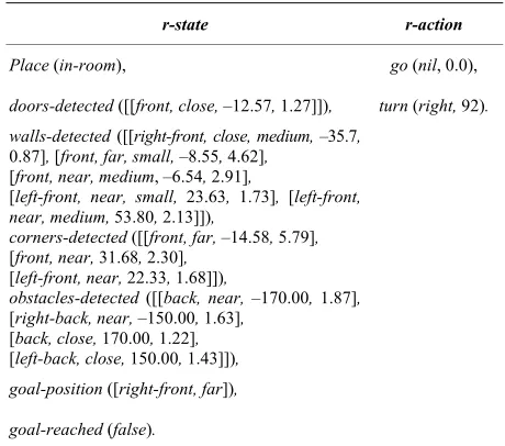
Table 2 shows an r-state-r-action pair generated with the previous predicates which corresponds to the values from Table 1. As can be seen, some of the r-state predi-cates (doors, walls, corners and obstacles detection) be-sides returning the nominal descriptions; they also return the numerical values of every detected element. The r-action predicates also return the odometer’s speed and the robot’s turning angle. These numerical values are used in the second stage of the method as described in Section 6. The discretized or nominal values, i.e., the r-states and r-actions descriptions, are used to learn a relational policy through rQ-learning as described below.
5. TS-RRLCA First Stage
TS-RRLCA starts with a set of human traces of the task that we want the robot to learn. A trace Τk = {fk1, fk2, …,
fkn} is a log of all the odometer, laser and sonar sensor’s
readings of the robot while it is performing a particular task. A trace-log is divided in frames; every frame is a register with all the low-level values of the robot’s sen-sors (fkj = {laser1 = 2.25, laser2 = 2.27, laser3 = 2.29, …,
sonar1 = 3.02, sonar2 = 3.12, sonar3 = 3.46, …, speed = 0.48, angle = 87.5}) at a particular time.
Once a set of traces (Τ1, Τ2, ..., Τm) has been given to
TS-RRLCA, every frame in the traces, is transformed
Table 2. Resulting r-state-r-action pair from the values in Table 1
r-state r-action
Place (in-room), go (nil, 0.0),
doors-detected ([[front, close, –12.57, 1.27]]), turn (right, 92). walls-detected ([[right-front, close, medium, –35.7,
0.87], [front, far, small, –8.55, 4.62],
[front, near, medium, –6.54, 2.91],
[left-front, near, small, 23.63, 1.73], [left-front, near, medium, 53.80, 2.13]]),
corners-detected ([[front, far, –14.58, 5.79],
[front, near, 31.68, 2.30],
[left-front, near, 22.33, 1.68]]),
obstacles-detected ([[back, near, –170.00, 1.87],
[right-back, near, –150.00, 1.63],
[back, close, 170.00, 1.22],
[left-back, close, 150.00, 1.43]]),
goal-position ([right-front, far]),
into natural landmarks along with the robot’s location. This transformed frames are given to the first order predicates to evaluate the set of relations, i.e., generate the corresponding r-state and r-action (as the one shown in Table 2). By doing this, every frame from the traces corresponds to an r-state-r-action pair and every one of these pairs is stored in a database (DB).
Algorithm 1 gives the pseudo-code for this Behav-ioural Cloning (BC) approach. At the end of this BC ap-proach, the DB contains r-state-r-action pairs correspond-ing to all the frames in the set of traces.
As the traces correspond to different examples of the same task and as they might have been generated by dif-ferent users, there can be several r-actions associated to the same r-state. RL is used to develop a control policy that selects the best r-action in each r-state.
5.1 Relational Reinforcement Learning
The RL algorithm selects the r-action that produces the greatest expected accumulated reward among the possi-ble r-actions in each r-state. Since we only used informa-tion from traces only a subset of all the possible r-acinforma-tions, for every r-state, are considered which significantly re-duces the search space. In a classical reinforcement learning framework a set of actions (A) is predefined for all of the possible states (S). Every time the agent reaches a new state, it must select one action from all of the pos-sible actions in S to reach a new state. In our RL ap-proach when the robot reaches a new r-state, it chooses one action from a subset of r-actions performed in that r-state in the traces.
In order to execute actions, each time the robot reaches an r-state, it retrieves from the DB the associated r-ac-tions. It chooses one according to its policy and the asso-ciated nominal value of the selected r-action is trans-formed into one of the following values:
1) For the predicate go, if the description of the r-action is front the corresponding value is 0.5 m/s, for
back the corresponding value is –0.5 m/s, and for nil the value is 0.0 m/s.
2) For the predicate turn the values are: slight-right = –45°, right = –90°, far-right = –135°, slight-left = 45°,
left = 90°, far-left = 135° and nil = 0°.
Once the r-action has been chosen and executed the robot gets into a new r-state and the previous process is repeated until reaching a final r-state.
Algorithm 2 gives the pseudo-code for this rQ-learning
approach. This is very similar to the Q-learning algo-rithm, except that the states and actions are characterized by relations.
By using only the r-state-r-action pairs from the traces (stored in the DB) our policy generation process is very fast and thanks to our relational representation, policies can be transferred to different, although similar office or
Algorithm 1. Behavioural cloning algorithm
Require: T1, T2,…Tn: Set of n traces with examples of the task the
robot has to learn.
Ensure: DB: r-state-r-action pairs database.
for i = 1 to n do
k← number of frames in the trace i
for j = 1 to k do
Transform frameij (frame j from trace i) into their
cor-responding natural landmarks and into the correspond-ing robot’s location.
Use the natural landmarks and the robot’s location to get the corresponding r-state (through the first order predicates).
Use the robot’s speed and angle to get the
corre-sponding r-action.
DB ← DB∪{r-state, r-action}. % Each register in DB contains an r-state with its corresponding r-action End for
End for
Algorithm 2. rQ-learning algorithm
Require: DB, r-state-r-action pairs database.
Ensure: functionQ: discrete actions relational control policy.
Initialize Q (St, At) arbitrarily
Repeat
st← robot’s sensors readings values.
Transform stinto its corresponding natural landmarks and into the corresponding robot’s location.
St←r-state (st)% Use those natural landmarks and the ro-bot’s location to get the corresponding r-state (through the first order predicates).
for each step of the episode do
Search the r-state (St) description in DB.
for each register in DB which contains the r-state (St) de-scription do
Get its corresponding r-actions
End for
Select an r-action Atto be executed in Sttrough an action selection policy (e.g., ε-greedy).
Execute action At, observe rt+1 and st+1
Transform st+1 into its corresponding natural landmarks and into the corresponding robot’s location.
St+1←r-state(st+1)% Use those natural landmarks and the
robot’s location to get the corresponding r-state (through the first order predicates).
Q(St, At)← Q(St, At) + α(rt+ 1 + γmaxAt+1 Q(St+1, At+1) - Q(St,
At))
St←St+1 End for
house-like environments. In the second stage, this dis-crete actions policy is transformed into a continuous ac-tions policy.
6. TS-RRLCA Second Stage
This second stage refines the coarse actions from the previously generated discrete actions policy. This is achieved using Locally Weighted Regression (LWR).
The idea is to combine discrete actions’ values given by the policy obtained in the first stage with the action’s values previously observed in the traces. This way the robot follows the policy, developed in the first stage, but the actions are tuned through a LWR process. What we do is to detect the robot’s actual r-state, then, for this r-state the previously generated discrete actions policy determines the action to be executed (Figure 4(a)). Be-fore performing the action, the robot searches in the DB
for all the registers that share this same r-state description (Figure 4(b)). Once found, the robot gets all of the nu-meric orientation and distance values from these registers. This orientation and distance values are used to perform a triangulation process. This process allows us to esti-mate the relative position of the robot from previous traces with respect to the robot’s actual position. Once this position has been estimated, a weight is assigned to the previous traces action’s values. This weight depends on the distance of the robot from the traces with respect to the actual robot’s position (Figure 4(c)). These weights are used to perform the LWR that produces continuous r-actions (Figure 4(d)).
The triangulation process is performed as follows. The robot R in the actual r-state (Figure 5(a)), senses and detects elements E and E’ (which can be a door, a corner, a wall, etc.). Each element has a relative distance (a and
(a) (b)
[image:6.595.311.536.94.178.2]
(c) (d)
Figure 4. Continuous actions developing process, (a) r-state and corresponding r-action; (b) a trace segment; (c) dis-tances and weights; (d) resulting continuous action
[image:6.595.82.261.504.682.2](a) (b) (c)
Figure 5. Triangulation process, (a) R robot’s r-state and identified elements; (b) R’robot from traces; (c) elements to be calculated
b) and a relative angle with respect to R. The angles are not directly used in this triangulation process, what we use is the absolute difference between these angles (α). The robot reads from the DB all the registers that share the same r-state description, i.e., that have the same r-state discretized values. The numerical angle and dis-tance values associated with these DB registers corre-spond to the relative distances (a’ and b’) from the robot
R’ in a trace relative to the same elements E and E’, and the corresponding angle β (Figure 5(b)). In order to know the distance between R and R’ (d) through this tri-angulation process, Equations (1)-(4) are applied.
2 2 2 cos( )
EE a b ab :Distance between E and E’. (1)
arcsin a EE/
: Angle between a’ and EE. (2)
arcsin( /a EE)
: Angle between a and EE. (3)
2 2 2 cos( )
d a a aa : Distance between R andR’.
(4) These four equations give the relative distance (d) be-tween R and R’. Once this value is calculated, a kernel is used to assign a weight (w). This weight is multiplied by the speed and angle values of the R’ robot’s r-action. The resulting weighted speed and angle values are then added to the R robot’s speed and angle values. This process is applied to every register read from the DB whose r-state description is the same as R and is repeated every time the robot reaches a new r-state.
To summarize this process, each time the robot reaches an r-state and chooses an r-action according to the learned policy; it retrieves from the DB all the regis-ters that share the same r-state. It uses the numerical val-ues of the retrieved r-states to evaluate the relative dis-tance of the position of the robot in a trace to the position of the robot in the actual r-state. Once all the distance values (di) are calculated we apply a Gaussian kernel (Equation (5)) to obtain a weight wi. We tried different
Gaussian kernel but further tests are needed.
2
( ) exp( )
i i i
w d d : Gaussian kernel. (5) Then, every weight wi is multiplied by the
corre-sponding speed and angle values (wi × speedDBi and wi ×
angleDBi) of the r-state-r-action pairs retrieved from the
DB. The resulting values are added to the discrete r-action (rAt = {disc_speed, disc_angle}) values of the
policy obtained in the first stage in order to transform this discrete r-action into a continuous action (Equations (6) and (7)) that is finally executed by the robot. This process is performed in real-time every time the robot reaches a new r-state.
continuous_speed = disc_speed + {w1 × speedDB1} + {w2
× speedDB2} + … + {wn × speedDBn}: LWR for
develop-ing the continuous speed. (6)
continuous_angle = disc_angle + {w1 × angleDB1} + {w2
× angleDB2} + … + {wn × angleDBn}: LWR for
develop-ing the continuous angle. (7) The weights are directly related to the distances be-tween the robots in the actual r-state to the r-states to the robot in the human traces stored in the DB. The closer the human traces registers are to the robot’s actual posi-tion, the higher the influence they have in transforming the discrete action into a continuous action.
The main advantage of our approach is the simple and fast strategy to produce continuous actions policies that, as will be seen in the following section, are able to pro-duce smoother and shorter paths in different environ-ments.
7. Experiments
For testing purposes, two types of experiments were per-formed:
1) Learning Curves: In these experiments we com-pared the number of iterations it takes our method
TS-RRLCA to learn a policy against classical Reinforce-ment Learning (RL) and against the rQ-learning algo-rithm (shown in Algoalgo-rithm 2) without using Behavioural Cloning approach, which we will refer to as Relational Reinforcement Learning (RRL).
2) Performance: In these experiments we compared the performance of the policies learned through TS-RRLCA
with discrete actions against the policies learned through
TS-RRLCA with continuous actions. Particularly we tested: How close the tasks are to the tasks performed by the user and how close the tasks are from obstacles in the environment.
3)Execution times.
These experiments were carried out in simulation (Player/Stage [16]) and with a real robot which is an
ActivMedia GuiaBot (www.activrobots.com).
Both robots (simulated and real) are equipped with a 180° front laser sensor and an array of four back sonars (located at –170°, –150°, 150° and 170°).
The laser range is 8.0 m and for the sonars is 6.0 m. The tasks in these experiments are “navigating through the environment” and “following an object”.
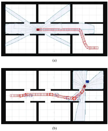
[image:7.595.307.537.418.696.2]The policy generation process was carried out in the map shown in Figure 6 (Map 1 with size 15.0 m × 9.0 m). For each of the two tasks a set of 20 traces was generated by the user. For the navigation tasks, the robot and the goal’s global position (for the goal-position predicate) were calculated using the work developed in [14]. For the following tasks we used a second robot which orien-tation and angle were calculated through the laser sensor.
Figure 6 shows an example of navigation and a follow-ing trace.
To every set of traces, we applied our approach to ab-stract the r-states and induce the subsets of relevant r- actions. Then, rQ-learning was applied to learn the poli- cies. For generating the policies, Q-values were initialized to –1, ε = 0.1, γ = 0.9 and α = 0.1. Positive reinforcement, r
(+100) was given when reaching a goal (within 0.5 m), negative reinforcement (–20) was given when the robot hits an element and no reward value was given otherwise (0).
(a)
(b)
7.1 Learning Curves
Our method (TS-RRLCA) was compared in the number of iterations it takes to develop a control policy, against classical reinforcement learning (RL) and against the
rQ-learning algorithm described in Algorithm 2, consid-ering all the possible r-actions (the 8 r-actions, shown in Section 4) per r-state (RRL).
For developing the “navigating through the environ-ment” policy with RL we discretized the state and action space as follows: the training Map 1, depicted in Figure 6, was divided in states of 25 cm2. Since this map’s size is
15 m × 9 m, the number of states is 2,160. In every state, one of the next 8 actions can be chosen to get into a new state which gives a total of 17,280 state-action pairs (This set of 8 actions correspond to the set of 8 r-actions we used in our rQ-learning algorithm).
1) front: robot goes forward 25 cm. 2) back: robot goes back 25 cm. 3) slight-right: robot turns –45°. 4) right: robot turns –90°. 5) far-right: robot turns –135°. 6) slight-left: robot turns 45°. 7) left: robot turns 90°. 8) far-left: robot turns 135°.
For developing the navigation policy with RRL we have 655 r-states with 8 possible r-actions for each r-state, this gives a total of 5,240 possible r-state-r-action pairs. The number of r-states corresponds to the total number of r-states in which the training map can be divided.
For developing the navigation policy with TS-RRLCA
we used 20 navigation traces from which 934 r-state- r-action pairs were obtained. As can be seen, by using our Behavioural Cloning approach we significantly re-duced the number of state-action pairs to consider in the learning process.
In each trace, every time our program performed a ro-bot’s sensors reading, which includes laser, sonars and odometer, we first transformed the laser and sonar read-ings into natural landmarks (as described in Section 3). These natural landmarks are sent to the predicates to generate the corresponding r-state, the corresponding r-action is generated by using the odometer’s readings (as described in Section 4). This gives an r-state-r-action pair such as the one shown in Table 2.
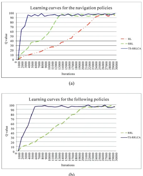
Figure 7(a) shows the learning curves of RL, RRL and
TS-RRLCA for a navigation policy. They show the ac-cumulated Q-values every 1,000 iterations. As can be seen from this figure, the number of iterations for devel-oping an acceptable navigation policy with TS-RRLCA is very low when compared to RRL and is significantly lower when compared to RL. It should be noted that the navigation policy learned with RL only works for going to a single destination state while the policies learned with our relational representation can be used to reach
(a)
[image:8.595.308.538.93.375.2](b)
Figure 7. Learning curves comparison, (a) learning curves for the navigation policies; (b) learning curves for the fol-lowing policies
several destination places in different environments. For developing the “following an object” policy, the number of r-state-r-action pairs using our relational rep-resentation (RRL) is 3,149, while the number of r-state- r-action pairs using the same representation but with be-havioural cloning (TS-RRLCA) is 1,406, obtained from 20 traces. For the following policy we only compared our approach against RRL.
Figure 7(b) shows the learning curves of these two methods. As can be seen the number of iterations that our method needs to generate an acceptable following policy is much lower than RRL.
To generate the continuous actions policies, LWR was applied using the Gaussian kernel for estimating weights. In the next section we compare the traces performed with the discrete actions policy with those using continuous actions.
7.2 Performance Tests
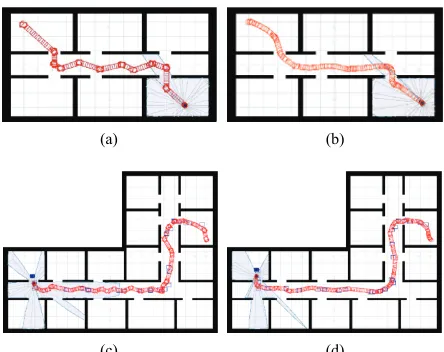
(a) (b)
[image:9.595.61.283.92.268.2](c) (d)
Figure 8. Navigation and following tasks performed with the policies learned with TS-RRLCA, (a) navigation task with discrete actions, Map 1; (b) navigation task with con-tinuous actions, Map 1; (c) following task with discrete ac-tions, Map 2; (d) following task with continuous acac-tions, Map 2
(a) (b) (c)
(d) (e) (f)
Figure 9. Navigation and following tasks examples from Map 3, (a) navigation task with discrete actions; (b) naviga-tion task with continuous acnaviga-tions; (c) naviganaviga-tion task per-formed by user; (d) following task with discrete actions; (e) Following task with continuous actions; (f) following task performed by user
[image:9.595.56.289.346.528.2]experiments were performed: 10 different navigation and 10 following tasks in each map, each of these tasks were executed first with the discrete actions policy from the first stage and then with the continuous actions policy from the second stage. Each task has a different distance to cover and required the robot to traverse through dif-ferent places. The minimum distance was 2 m. (Manhat-tan dis(Manhat-tance), and it was gradually increased up to 18 m.
Figure 8 shows navigation (on the top) and a following task (on the bottom) performed with discrete and
con-tinuous actions policies respectively.
Figure 9 shows navigation and a following task per-formed with the real robot, with the discrete and with the continuous actions policy.
As we only use the r-state-r-action pairs from the traces developed by the user in Map 1 (as the ones shown in
Figure 6), when moving the robot to the new environ-ments (Map 2 and Map 3), sometimes, it was not able to match the new map’s r-state with one of the previously visited states by the user in the traces examples. So when the robot reached an unseen r-state, it asked the user for guidance. Through a joystick, the user indicates the robot which r-action to execute in the unseen r-state and the robot saves this new r-state-r-action pair in the DB. Once the robot reaches a known r-state, it continues its task. As the number of experiments increased in these new maps, the number of unseen r-states was reduced. Table 3 shows the number of times the robot asked for guidance in each map and with each policy.
Figure 10(a) shows results in terms of the quality of the performed tasks with the real robot. This comparison is made against tasks performed by humans (For Figures 10(a), 10(b) and 11, the following acronyms are used, NPDA: Navigation Policy with Discrete Actions, NPCA: Navigation Policy with Continuous Actions, FPDA: Fol-lowing Policy with Discrete Actions and FPCA: Follow-ing Policy with Continuous Actions).
All of the tasks performed in the experiments with the real robot, were also performed by a human using a joy-stick (Figures 9(c) and 9(f)), and logs of the paths were saved. The graphic shows the normalized quadratic error between these logs and the trajectories followed by the robot with the learned policy.
Figure 10(b) shows results in terms of how closer the robot gets to obstacles. This comparison is made using the work developed in [17]. In that work, values were given to the robot accordingly to its proximity to objects or walls. The closer the robot is to an object or wall the higher cost it is given. Values were given as follows: if the robot is very close to an object (between 0 m and 0.3 m) a value of –100 is given, if the robot is close to an object (between 0.3 m and 1.0 m) a value of –3 is given, if the robot is near an object (between 1.0 m and 2.0 m) a value of –1 is given, otherwise a value of 0 is given. As can be seen in the figure, quadratic error and penalty values for continuous actions policies are lower than those with discrete actions. Policies developed with this method allow a close-to- human execution of the tasks and tend to use the available free space in the environment.
7.3 Execution Times
Table 3. Number of times the robot asked for guidance in the experiments
Policy type Map 1 Map 2 Map 3 Total
Navigation 2 6 14 22
Following 7 15 27 49
(a)
[image:10.595.57.289.122.531.2](b)
Figure 10. Navigation and following results of the tasks performed by the real robot, (a) quadratic error values; (b) penalty values
continuous actions. Every navigating or following ex- periment, that we carried out, was performed first with discrete actions and then with continuous actions.
As can be seen in Figure 11, continuous actions poli-cies execute faster paths than the discrete actions policy despite our triangulation and LWR processes.
8. Discussion
In this work, we introduced a method for teaching a robot how to perform a new task from human examples. Ex-perimentally we showed that tasks learned with this method and performed by the robot are very similar to
Figure 11. Execution times results
those tasks when performed by humans. Our two-stage method learns, in the first stage, a rough control policy which, in the second stage, is refined, by means of Locally Weighted Regression (LWR), to perform continuous ac-tions. Given the nature of our method we can not guar-anteed to generate optimal policies. There are two reasons why this can happen: 1) the actions performed by the user in the traces may not part of the optimal policy. In this case, the algorithm will follow the best policy given the known actions but will not be able to generate an optimal policy. 2) The LWR approach can take the robot to states that are not part of the optimal policy, even if they are smoother and closer to the user’s paths. This has not rep-resented a problem in the experiments that we performed.
With the Behavioural Cloning approach we observed around a 75% reduction in the state-action space. This reduction depends on the traces given by the user and on the training environment. In a hypothetical optimal case, where a user always performs the same action in the same state, the system only requires to store one action per state. This, however, is very unlikely to happen due to the con-tinuous state and action space and the uncertainty in the outcomes of the actions perform with a robot.
9. Conclusions and Future Work
rooms, corridors, doors, walls, etc., and can be re-used for different tasks and on different house or office-like envi-ronments. The policies were learned on a simulated en-vironment and later tested on a different simulated envi-ronment and on an envienvi-ronment with a real robot with very promising results.
There are several future research directions that we are considering. In particular, we would like to include an exploration strategy to identify non-visited states to com-plete the traces provided by the user. We are also explor-ing the use of voice commands to indicate the robot which action to take when it reaches an unseen state.
10. Acknowledgements
We thank our anonymous referees for their thoughtful and constructive suggestions. The authors acknowledge to CONACyT the support provided through the grant for MSc. studies number 212418 and in part by CONACyT project 84162.
REFERENCES
[1] C. Watkins, “Learning from Delayed Rewards,” PhD Thesis, University of Cambridge, England, 1989. [2] K. Conn and R. A. Peters, “Reinforcement Learning with
a Supervisor for a Mobile Robot in a Real-World Envi-ronment,” International Symposium on Computational Intelligence in Robotics and Automation, Jacksonville, FI, USA, June 20-23, 2007, pp. 73-78.
[3] E. F. Morales and C. Sammut, “Learning to Fly by Com-bining Reinforcement Learning with Behavioural Clon-ing,” Proceedings of the Twenty-First International Con-ference on Machine Learning, Vol. 69, 2004, pp. 598- 605.
[4] J. Peters, S. Vijayakumar and S. Schaal, “Reinforcement Learning for Humanoid Robotics,” Proceedings of the Third IEEE-RAS International Conference on Humanoid Robots, Karlsruhe, Germany, September 2003, pp. 29-30. [5] W. D. Smart, “Making Reinforcement Learning Work on
Real Robots,” Department of Computer Science at Brown University Providence, Rhode Island, USA, 2002. [6] W. D. Smart and L. P. Kaelbling, “Effective
Reinforce-ment Learning for Mobile Robots,” Proceedings of the 2002 IEEE International Conference on Robotics and Automation, Washington, DC, USA, 2002, pp. 3404-3410.
[7] R. S. Sutton and A. G. Barto, “Reinforcement Learning: An introduction,” MIT Press, Cambridge, MA, 1998. [8] L. Torrey, J. Shavlik, T. Walker and R. Maclin,
“Rela-tional Macros for Transfer in Reinforcement Learning,”
Lecture Notes in Computer Science, Vol. 4894, 2008, pp. 254-268.
[9] Y. Wang, M. Huber, V. N. Papudesi and D. J. Cook, “User-guided Reinforcement Learning of Robot Assistive Tasks for an Intelligent Environment,” Proceedings of the
2003 IEEE/RSJ International Conference on Intelligent Robots and Systems, Las Vegas, NV, 2003, pp. 27-31. [10] I. Bratko, T. Urbancic and C. Sammut, “Behavioural
Cloning of Control Skill,” In: R. S. Michalski, I. Bratko and M. Kubat, Ed., Machine Learning and Data Mining, John Wiley & Sons Ltd., Chichester, 1998, pp. 335-351. [11] A. Cocora, K. Kersting, C. Plagemann, W. Burgard and L.
De Raedt, “Learning Relational Navigation Policies,”
IEEE/RSJ International Conference on Intelligent Robots and Systems, Beijing, China, October 9-15, 2006, pp. 2792-2797.
[12] C. Gaskett, D. Wettergreen and A. Zelinsky, “Q-learning in Continuous State and Action Spaces,” In Australian Joint Conference on Artificial Intelligence, Australia, 1999, pp. 417-428.
[13] F. Aznar, F. A. Pujol, M. Pujol and R. Rizo, “Using Gaussian Processes in Bayesian Robot Programming,”
Lecture notes in Computer Science, Vol. 5518, 2009, pp. 547-553.
[14] S. F. Hernández and E. F. Morales, “Global Localization of Mobile Robots for Indoor Environments Using Natural Landmarks,” IEEE Conference on Robotics, Automation and Mechatronics, Bangkok, September 2006, pp. 29-30. [15] J. Herrera-Vega, “Mobile Robot Localization in Topo-logical Maps Using Visual Information,” Masther’s thesis (to be publised), 2010.
[16] R. T. Vaughan, B. P. Gerkey and A. Howard, “On Device Abstractions for Portable, Reusable Robot Code,” Pro-ceedings of the 2003 IEEE/RSJ International Conference on Intelligent Robots and Systems, Vol. 3, 2003, pp. 2421- 2427.