04 August 2020
POLITECNICO DI TORINO
Repository ISTITUZIONALE
Design techniques to support aircraft systems development in a collaborative MDO environment / Boggero, Luca. - (2018 Jul 06).
Original
Design techniques to support aircraft systems development in a collaborative MDO environment
Publisher: Published DOI:10.6092/polito/porto/2710702 Terms of use: openAccess Publisher copyright
(Article begins on next page)
This article is made available under terms and conditions as specified in the corresponding bibliographic description in the repository
Availability:
This version is available at: 11583/2710702 since: 2018-07-10T12:24:31Z Politecnico di Torino
Doctoral Dissertation
Doctoral Program in Aerospace Engineering (30th Cycle)
Design techniques to support aircraft
systems development in a
collaborative MDO environment
By
Luca Boggero
******Supervisor(s):
Prof. Sabrina Corpino, Supervisor Prof. Nicole Viola, Co-Supervisor Dr. Elena Valfrè (Leonardo), Co-Supervisor
Doctoral Examination Committee:
Prof. Susan Liscouët-Hanke, Referee, Concordia University Prof. Pat Piperni, Referee, Clarkson University
Prof. Andreas Strohmayer, University of Stuttgart Prof. Eugenio Brusa, Politecnico di Torino
Prof. Paolo Maggiore, Politecnico di Torino
Politecnico di Torino 2018
Declaration
I hereby declare that, the contents and organization of this dissertation constitute my own original work and does not compromise in any way the rights of third parties, including those relating to the security of personal data.
Luca Boggero 2018
* This dissertation is presented in partial fulfillment of the requirements for
Acknowledgment
I have carried out the doctorate within the context of the Italian national project TIVANO, which has been funded by the Italian Ministry of Education, University and Research. Thanks to this project, I had the opportunity of fulfilling my research activities at Politecnico di Torino, at Leonardo – Aircraft Division in Turin and at the German Aerospace Center DLR in Hamburg. In each place I met very special people, whom I would like to acknowledge.
In particular, I thank my thesis supervisors Prof. Sabrina Corpino and Prof. Nicole Viola for their support, suggestions and contributes to my research. Many thanks to all the office mates, especially Marco, Francesca, Sara, Roberta, Davide, Valeria and Fabrizio, for the good times I spent with them in these years. Furthermore, I would like to acknowledge all the professors, researchers and PhD students who have been involved within the TIVANO project and with whom I had meetings, research activities and collaborations.
A special thanks goes to Elena Valfrè and Marco Baroero of Leonardo – Aircraft Division, for giving me the opportunity of working within an industrial context and for their advice. During my training in Leonardo I have also been advised by Marco Foglino, Bruno Di Giandomenico, Guido Pavan and Luciana Loverde. To them goes my gratitude for having shared with me their time, knowledge and experience. I am thankful also to all the people I met and joined in Leonardo, especially all the office colleagues.
I would like to say thanks – or even better, “danke schön” – to all the researchers I met during the three-month internship I spent at the Integrated Aircraft Design department of the DLR of Hamburg. Special acknowledgments go to Pier Davide Ciampa and Björn Nagel for having hosted me and to Matthias and Prajwal for having shared with me their office (and the Indian food). Thanks to all of them for their tips concerning my research activity, but also about the many attractions to visit in Hamburg.
I owe my gratitude to my parents, Piera and Stefano, for having encouraged me and supported every decision and choice I have taken all along my studies and my doctorate. I would like to thank them and dedicate my thesis.
Thanks to everyone who will be willing to read my dissertation, wishing to receive many feedbacks and comments, and hoping to having contributed as much as possible to the aircraft design discipline.
Abstract
The aircraft design is a complex multidisciplinary and collaborative process. Thousands of disciplinary experts with different design competences are involved within the whole development process. The design disciplines are often in contrast with each other, as their objectives might be not coincident, entailing compromises for the determination of the global optimal solution. Therefore, Multidisciplinary Design and Optimization (MDO) algorithms are being developed to mathematically overcome the divergences among the design disciplines. However, a MDO formulation might identify an optimal solution, but it could be not sufficient to ensure the success of a project. The success of a new project depends on two factors. The first one is relative to the aeronautical product, which has to be compliant with all the capabilities actually demanded by the stakeholders. Furthermore, a “better” airplane may be developed in accordance with customer expectations concerning better performance, lower operating costs and fewer emissions. The second important factor refers to the competitiveness among the new designed product and all the other competitors. The Time-To-Market should be reduced to introduce in the market an innovative product earlier than the other aeronautical industries. Furthermore, development costs should be decreased to maximize profits or to sell the product at a lower price. Finally, the development process must reduce all the risks due to wrong design choices.
These two main motivations entail two main objectives of the current dissertation. The first main objective regards the assessment and development of design techniques for the integration of the aircraft subsystems conceptual design discipline within a collaborative and multidisciplinary development methodology. This methodology shall meet all the necessities required to design an optimal and competitive product. The second goal is relative to the employment of the proposed design methodology for the initial development of innovative solutions. As the design process is multidisciplinary, this thesis is focused on the on-board systems discipline, without neglecting the interactions among this discipline with all the other design disciplines. Thus, two kinds of subsystems are treated in the current
dissertation. The former deals with hybrid-electric propulsion systems installed aboard Remotely Piloted Aerial Systems (RPASs) and general aviation airplanes. The second case study is centered on More and All Electric on-board system architectures, which are characterized by the removal of the hydraulic and/or pneumatic power generation systems in favor of an enhancement of the electrical system.
The proposed design methodology is based on a Systems Engineering approach, according to which all the customer needs and required system functionalities are defined since the earliest phase of the design. The methodology is a five-step process in which several techniques are implemented for the development of a successful product. In Step 1, the design case and the requirements are defined. A Model Based Systems Engineering (MBSE) approach is adopted for the derivation and development of all the functionalities effectively required by all the involved stakeholders. All the design disciplines required in the MDO problem are then collected in Step 2. In particular, all the relations among these disciplines – in terms of inputs/outputs – are outlined, in order to facilitate their connection and the setup of the design workflow. As the present thesis is mainly focused on the on-board system design discipline, several algorithms for the preliminary sizing of conventional and innovative subsystems (included the hybrid propulsion system) are presented. In the third step, an MDO problem is outlined, determining objectives, constraints and design variables. Some design problems are analyzed in the present thesis: un-converged and converged Multidisciplinary Design Analysis (MDA), Design Of Experiments (DOE), optimization. In this regard, a new multi-objective optimization method based on the Fuzzy Logic has been developed during the doctoral research. This proposed process would define the “best” aircraft solution negotiating and relaxing some constraints and requirements characterized by a little worth from the user perspective. In Step 4, the formulation of the MDO problem is then transposed into a MDO framework. Two kinds of design frameworks are here considered. The first one is centered on the subsystems design, with the aim of preliminarily highlighting the impacts of this discipline on the entire Overall Aircraft Design (OAD) process and vice-versa. The second framework is distributed, as many disciplinary experts are involved within the design process. In this case, the level of fidelity of the several disciplinary modules is higher than the first framework, but the effort needed to setup the entire workflow is much higher. The proposed methodology ends with the investigation of the design space through the implemented framework, eventually selecting the solution of the design problem (Step 5).
The capability of the proposed methodology and design techniques is demonstrated by means of four application cases. The first case study refers to the initial definition of the physical architecture of a hybrid propulsion system based on a set of needs and capabilities demanded by the customer. The second application study is focused on the preliminary sizing of a hybrid-electric propulsion system to be installed on a retrofit version of a well-known general aviation aircraft. In the third case study, the two kinds of MDO framework previously introduced are employed to design conventional, More Electric and All Electric subsystem architectures for a 90-passenger regional jet. The last case study aims at minimizing the aircraft development costs. A Design-To-Cost approach is adopted for the design of a hybrid propulsion system.
Contents
1. Motivations and objectives of the research ... 1
1.1Introduction ... 1
1.2Design of innovative on-board systems ... 4
1.2.1 Conventional and More/All Electric subsystem architectures ... 7
1.2.2 Hybrid-electric propulsion system ... 10
1.3Literature survey on current design methodologies ... 14
1.3.1 The enhancement of the aircraft design process ... 14
1.3.2 On-board systems design methodologies ... 18
1.4Main objectives of the research and structure of the thesis ... 23
2. A Systems Engineering approach in a collaborative design framework .. 27
2.1Introduction ... 27
2.2A Systems Engineering approach ... 28
2.3The Design-To-Cost ... 31
2.3.1 Models for costs estimation ... 33
2.4A collaborative design framework ... 36
2.5The importance of modeling in systems design ... 38
3. Integration of subsystems design in a collaborative MDO process ... 45
3.1A collaborative design methodology ... 45
3.2Step 1: Define design case and requirements ... 47
3.2.1 The aircraft functional design ... 48
3.3Step 2: Specify complete and consistent data model and competences 52 3.3.1 Integration of the on-board systems discipline within a multidisciplinary design context ... 53
3.3.2 An on-board systems design module ... 58
3.4.1 Fuzzy Logic multi-objective optimization ... 79
3.5Step 4: Implement and verify the design framework ... 82
3.5.1 Example of a first Generation MDO framework... 83
3.5.2 Example of a third Generation MDO framework ... 94
3.6Step 5: Create and select the design solution ... 99
3.7Integration of a Design-To-Cost approach within the MDO process ... 99
4. Design case studies ... 103
4.1Introduction ... 103
4.2Conceptual functional design of a Hybrid Propulsion System ... 106
4.3Design and optimization of hybrid propulsion systems ... 116
4.3.1 Reference aircraft ... 118
4.3.2 Case 1: Design of the conventional Piper PA-38 ... 119
4.3.3 Case 2: Design of a 30% hybrid Piper PA-38 ... 122
4.3.4 Case 3: DOE of hybridization degrees ... 125
4.3.5 Case 4: Multi-objective optimization through the Fuzzy Logic . 129 4.4Design and optimization of on-board system architectures ... 133
4.4.1 Reference aircraft ... 134
4.4.2 Design of the aircraft on-board systems ... 138
4.4.3 On-board systems impact on the OAD ... 141
4.4.4 DOE of on-board system architectures ... 149
4.5Design-To-Cost applied to hybrid powered airplanes ... 155
4.5.1 Cost estimation of the traditional propulsion system ... 156
4.5.2 Definition of the target cost... 159
4.5.3 Identification of the alternative system architectures ... 159
4.5.4 Preliminary design of the alternative system architectures ... 161
4.5.5 Cost estimation of the alternative system architectures ... 162
4.5.6 Selection of the optimal system architecture ... 165
List of Figures
Figure 1: Two innovative concept studies: (a) the BWB and (b) the joined-wing
aircraft [15]. ... 3
Figure 2: Knowledge about the design, design freedom and cost of changes during the aircraft development process (adapted from [5]). ... 4
Figure 3: Impacts of on-board systems on the entire aircraft [20]. ... 5
Figure 4: Transformation of secondary power – adapted from [18]. ... 6
Figure 5: Schemas of (a) state-of-the-art and (b) More Electric systems architectures [26]. ... 8
Figure 6: Boeing 787 electric loads [6]. ... 9
Figure 7: Diamond DA36 E-Star [www.airliners.net]. ... 10
Figure 8: Schema of the series hybrid architecture. ... 11
Figure 9: Schema of the parallel hybrid architecture. ... 12
Figure 10: Flight Design’s parallel hybrid bench (adapted from [www.wired.com]). ... 13
Figure 11: Comparison of life cycle models [101]. ... 30
Figure 12: “V” model. ... 31
Figure 13: AACE’s cost estimation classes [106]. ... 34
Figure 14: Generations of MDO frameworks: 1st (a), 2nd (b) and 3rd (c) generation [109]. ... 37
Figure 15: SysML diagrams: schematic. ... 40
Figure 16: SysML diagrams: overview (adapted from [82]). ... 41
Figure 17: Phases of the IBM Harmony methodology [82]. ... 50
Figure 18: Effects of subsystems on OAD disciplines (adapted from [122]). 54 Figure 19: Landing gear retraction schema (adapted from [20]). ... 61
Figure 20: Estimation of the gravitational load acting on the nose landing gear. ... 61
Figure 22: Continuously and cyclically heated areas on the wing surface [25].
... 66
Figure 23: Schema of the emergency descent after take-off [144]. ... 74
Figure 24: Example of XDSM [4]... 79
Figure 25: Example of Membership Function of y. ... 81
Figure 26: Additional examples of Membership Functions of y. ... 82
Figure 27: Example of a first Generation MDO framework (adapted from [174]). ... 84
Figure 28: Statistical evaluation of turboprop (a) and turbofan (b) engines mass. ... 88
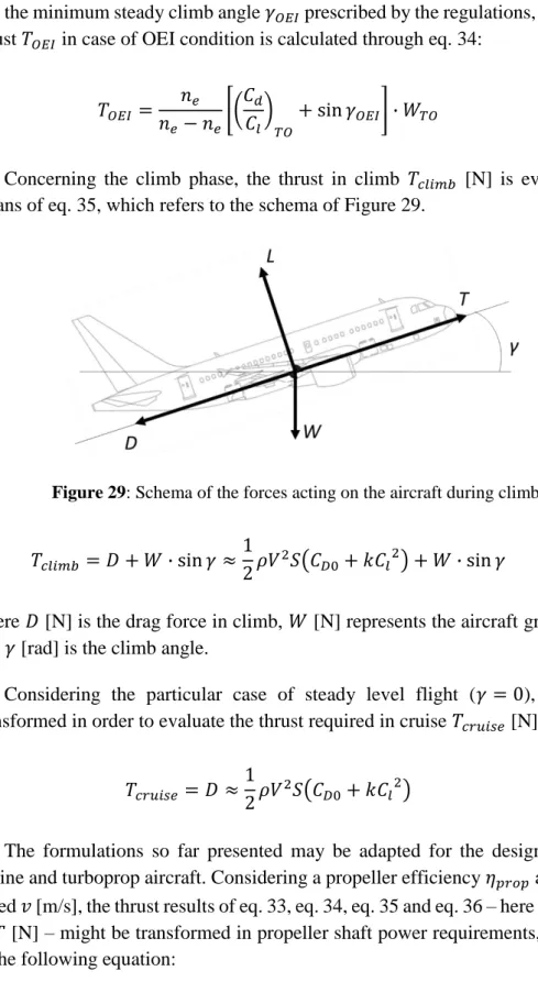
Figure 29: Schema of the forces acting on the aircraft during climb. ... 91
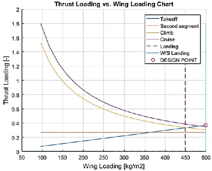
Figure 30: Example of a typical “Thrust Loading vs. Wing Loading” chart. . 92
Figure 31: Example of a Design and Optimization framework [147]. ... 93
Figure 32: Example of a third Generation MDO framework [119]. ... 96
Figure 33: Implementation of ASTRID within the AGILE MDO framework. ... 97
Figure 34: UC Diagram of the Hybrid Propulsion System. ... 109
Figure 35: Black-Box Activity Diagram of the UC “Provide propulsive power”. ... 111
Figure 36: Black-Box Sequence Diagram of the UC “Provide propulsive power”. ... 112
Figure 37: Statechart Diagram of the UC “Provide propulsive power”. ... 113
Figure 38: Different states of the system. ... 114
Figure 39: BDD of the Hybrid Propulsion System. ... 115
Figure 40: DSM of the 1st Generation MDO... 117
Figure 41: Piper PA-38 Tomahawk [www.commons.wikimedia.org]. ... 119
Figure 42: XDSM of the 1st Generation MDO (converged MDA problem). 120 Figure 43: Graphic results of the conventional Piper PA-38: Power Loading vs. Wing Loading Chart [142]. ... 121
Figure 44: Graphic results of the conventional Piper PA-38: Climb profile [142]. ... 122
Figure 45: “Power Loading vs. Wing Loading” Chart of the 30% hybrid Piper
PA-38 [142]. ... 123
Figure 46: XDSM of the 1st Generation MDO (DOE converged MDA problem). ... 126
Figure 47: Bar charts of the design results varying the hybridization degree: (a) Empty mass; (b) Fuel mass; (c) MTOM; (d) Minimum safety altitude [142]. .... 127
Figure 48: Climb profiles for different hybridization degrees [142]. ... 128
Figure 49: XDSM of the 1st Generation MDO (optimization problem). ... 130
Figure 50: Contour lines of the global fuzzy score – Fixed Range and TOFL [147]. ... 133
Figure 51: 3D model of the reference regional jet [194]... 135
Figure 52: Four on-board system architectures [174]. ... 136
Figure 53: Subsystems mass comparison for the four on-board system architectures. ... 143
Figure 54: Regional jet electric shaft power off-takes. ... 146
Figure 55: Regional jet hydraulic shaft power off-takes. ... 146
Figure 56: Regional jet bleed air off-takes. ... 147
Figure 57: Regional jet global masses estimated through the 1st and the 3rd Generation MDO frameworks: (a) OEM; (b) Fuel mass and (c) MTOM. ... 148
Figure 58: Flowchart of the workflow for the design of the 124 subsystem architectures (adapted from [200]). ... 151
Figure 59: Black-Box Activity Diagram of the UC “Provide propulsive power” relative to the design of the traditional propulsion system. ... 157
Figure 60: BDD of the traditional propulsion system. ... 158
Figure 61: White-Box Sequence Diagram of the UC “Provide propulsive power”. ... 164
List of Tables
Table 1: Pros and cons of the series hybrid architecture [35]. ... 11
Table 2: Pros and cons of the parallel hybrid architecture [36]. ... 12
Table 3: Typical causes of project failures [103]. ... 29
Table 4: Example of fidelity levels for aircraft design disciplines [111]. ... 39
Table 5: Participative agents of the collaborative MDO framework (adapted from [119]). ... 47
Table 6: Summary of design disciplines affected by on-board systems. ... 57
Table 7: Rolling friction coefficient μ in different taxiway surfaces [104]. ... 73
Table 8: Specific energy ranges of some batteries [146]. ... 77
Table 9: Air-Vehicle and Propulsion System Level Requirements. ... 107
Table 10: Functions allocation to system components... 116
Table 11: Piper PA-38 Tomahawk main specifications [191]. ... 118
Table 12: Results comparison between the “real” Piper PA-38 and the “designed” Piper PA-38. ... 119
Table 13: Resulting specifications of the 30% hybrid Piper PA-38 (adapted from [142]). ... 124
Table 14: Additional results of the 30% hybrid Piper PA-38 (adapted from [142]). ... 124
Table 15: Results comparison of different hybridization degrees (adapted from [142]). ... 125
Table 16: Objective functions and relative fuzzy sets [147]. ... 129
Table 17: Results of the multi-objective optimization [147]. ... 131
Table 18: Requirements of the civil regional jet [193]. ... 134
Table 19: Main results of the AGILE reference regional jet [194]. ... 135
Table 20: Main specifications of the regional jet movable surfaces ( [195], [196], [197], [198]. ... 139
Table 21: Main specifications of the regional jet landing gear retraction system.
... 139
Table 22: Thermal loads of the regional jet. ... 140
Table 23: Calibration of the 1st Generation MDO framework. ... 141
Table 24: Aircraft on-board systems mass budget. ... 142
Table 25: Regional jet electric shaft power off-takes. ... 144
Table 26: Regional jet hydraulic shaft power off-takes. ... 144
Table 27: Regional jet electric bleed air off-takes. ... 145
Table 28: Regional jet global masses estimated through the 1st and the 3rd Generation MDO frameworks. ... 148
Table 29: Alternative design options for the different architectures. ... 149
Table 30: Subset of the 124 on-board system architectures. ... 150
Table 31: Subset of DOE results: systems mass increasing. ... 151
Table 32: Subset of DOE results: total mass increasing. ... 152
Table 33: Main subsystems results and their considered variation (adapted from [202]). ... 153
Table 34: Validation of the OAD response model. ... 154
Table 35: Application of the OAD response model. ... 155
Table 36: Subset of high level requirements of the air-vehicle equipped with a traditional propulsion system. ... 156
Table 37: Subset of the preliminary design results of components of the traditional propulsion system. ... 158
Table 38: Cost of the components of the traditional propulsion system. ... 159
Table 39: Importance of the capabilities of the five alternative architectures. ... 160
Table 40: Subset of the preliminary design results of components of “Hyb_Sys” architecture. ... 161
Table 41: Cost and “value” of the alternative solutions of propulsion system. ... 165
List of Acronyms
AACE Association for Advancement of Cost Engineering ACM Air Cycle Machine
AEA All Electric Aircraft AGB Accessory Gear Box APU Auxiliary Power Unit AR Aspect Ratio
ASDR Accelerate-Stop Distance Required ATA Air Transport Association
BDD Block Definition Diagram BFL Balanced Field Length BPR By-Pass Ratio
BWB Blended Wing Body CAU Cold Air Unit
CCS Commercial Cabin System CER Cost Estimation Relationship CFD Computational Fluid Dynamics CFP COSMIC Function Point
CIAM Central Institute of Aviation Motor CIPS Cowl Ice Protection System
CPACS Common Parametric Aircraft Configuration Schema CS Certification Specification
DOC Direct Operating Cost DOE Design Of Experiments DSM Design Structure Matrix DTC Design-To-Cost
EBHA Electrical Backup Hydraulic Actuator ECS Environmental Control System EDP Engine Driven Pump
EHA Electro-Hydrostatic Actuator EM Electric Motor
EMA Electro-Mechanical Actuator EMP Electric Motor Pump
EPDS Electric Power Distribution System
EPGDS Electric Power Generation and Distribution System FAA Federal Aviation Administration
FCS Flight Control System FEM Finite Element Method FOD Foreign Object Debris GCS Ground Control Station
HALE High Altitude Long Endurance HEPS Hybrid-Electric Propulsion System
HEV Hybrid Electric Vehicle
HPGDS Hydraulic Power Generation and Distribution System IBD Internal Block Diagram
ICE Internal Combustion Engine IDEA Integrated Digital Electric Aircraft IDG Integrated Drive Generator IFE In-Flight Entertainment IM Induction Motor
INCOSE International Council on Systems Engineering IPS Ice Protection System
ISR Intelligence, Surveillance, Reconnaissance IT Information Technology
JPL Jet Propulsion Laboratory KBE Knowledge Based Engineering LCC Life Cycle Cost
LFL Landing Field Length M&S Model & Simulation
MALE Medium Altitude Long Endurance MBSE Model Based Systems Engineering MDA Multidisciplinary Design Analysis
MDAO Multidisciplinary Design Analysis and Optimization MDO Multidisciplinary Design and Optimization
MEA More Electric Aircraft MF Membership Function
MICADO Multidisciplinary Integrated Conceptual Aircraft Design MLM Maximum Landing Mass
MLW Maximum Landing Weight
MPGDS Mechanical Power Generation and Distribution System MTOM Maximum Take-Off Mass
MTOW Maximum Take-Off Weight OAD Overall Aircraft Design OEI One Engine Inoperative OEM Operating Empty Mass OEW Operating Empty Weight
OOSEM Object–Oriented Systems Engineering Methodology PBS Product Breakdown Structure
PIDO Process Integration and Design Optimization PM Permanent Magnet
PPGDS Pneumatic Power Generation and Distribution System PrADO Preliminary Aircraft Design and Optimization
RAMS Reliability, Availability, Maintainability, Safety RANS Reynolds Averaged Navier-Stokes
RAT Ram Air Turbine
RPAS Remotely Piloted Aerial System RSM Response Surface Model
RTO Rejected Take Off SE Systems Engineering SFC Specific Fuel Consumption SLOC Source Lines of Code SRM Switched Reluctance Motor
SRS Stakeholder Requirement Specification SysML System Modeling Language
SYSMOD Systems Modeling Process TAS True Air Speed
TLAR Top Level Aircraft Requirement TODR Take-Off Distance Required TOFL Take-Off Field Length
TRAS Thrust Reverser Actuation System TRU Transformer Rectifier Unit TTM Time To Market
UAV Unmanned Aerial Vehicle
UC Use Case
UML Unified Modeling Language VCM Vapor Cycle Machine VLM Vortex Lattice Method
VMS Vehicle Management System WER Weight Estimation Relationship WIPS Wing Ice Protection System XDSM eXtended Design Structure Matrix
Chapter 1
Motivations and objectives of the
research
1.1
Introduction
The aircraft design is a long and complex process. Thousands of employees are involved along the entire development1 phase, which might last for several years, on average five [1]. Moreover, aircraft design is a multidisciplinary and collaborative process. Several design disciplines – i.e. domains of the aircraft design process – are indeed involved within the development of the new product. The main design disciplines encompass aerodynamics, structures, propulsion, on-board systems (equivalently referred as subsystems and aircraft systems), flight mechanics, performance, overall aircraft synthesis, emissions, costs estimation. All these disciplines often generate conflicts and contrasts between them, as their optimal solutions are not converging to a unique one. For instance, a thinner wing is required to reduce aerodynamic drag, but a thicker one is lighter [2]. Hence, a balance between the aerodynamic and structural design is needed to achieve the “best” solution, which results from the compromise between the two disciplines. To overcome – or at least to minimize – the conflicts among all the design
2 Motivations and objectives of the research
disciplines, Multidisciplinary Design and Optimization (MDO) techniques are employed by aeronautical industries and research centers. As stated by Sobieski [3], MDO is “a methodology for design of complex engineering systems that are governed by mutually interacting physical phenomena and made up of distinct interacting subsystems (suitable for systems for which) in their design, everything influences everything else”. Entering in the details of the MDO architectures, techniques and algorithms is out of the scope of the present dissertation, as detailed studies are collected in other works in literature, as in [2], [3], [4], [5]. In simple terms, the goal of a MDO problem is the optimization of a measure of merit – often named “design objective” – that generally is represented by the minimization of the aircraft development cost or by the minimization of the Maximum Take-Off Weight (MTOW). In addition, the design and optimization process is subjected to constraints, such as performance characteristics like the take-off distance requirement, and geometrical limits, for instance the maximum wingspan. The MDO techniques aim at overcoming all the boundaries among the disciplines, obtaining the global optimal solution, in accordance with all the design requirements.
In addition to this, new market demands are moving towards products with higher performance, more environmentally friendly and with lower operating costs (e.g. with lower fuel consumptions). Since a few years, the main aeronautical industries are developing technological improvements in several disciplines, for instance in:
- structures, with the increment of the percentage of composite materials, hence designing lighter aircraft. For example, the Boeing Company states that the high use of composite materials (about 50%) for the airframe and the primary structure of the Boeing 787 entails up to 20% of weight savings and a reduction of nearly 30% of the structures maintenance costs [6]. - propulsion, with the introduction of more efficient engines, as the new Pratt
& Whitney PW1000G [7] installed aboard the Airbus A320 neo family, where significant benefits in terms of fuel consumption (up to -20% per seat by 2020), operating costs and engine noise and polluting NOx emissions (-50%) are claimed [8].
- aircraft subsystems, with the development of innovative on-board systems characterized by more efficient engines power off-takes. Innovative on-board system architectures are already adopted in civil aviation, as the case of the Boeing 787 and the Airbus A380 (see Section 1.2).
Introduction 3
Moreover, since many years several research centers and universities are carrying on projects focused on the study and development of innovative concepts and disruptive technologies. Examples of these novel solutions are represented by the Blended Wing Body (BWB) aircraft ( [9], [10], [11]), or the joined-wing aircraft ( [12], [13], [14]). The main objectives of these two kinds of concept are the reduction of the aerodynamic drag or the decrease of the structural weight. Other studies are also focused on the hybrid-electric propulsion, as described in Section 1.2.
Figure 1: Two innovative concept studies: (a) the BWB and (b) the joined-wing aircraft [15].
However, a new innovative and disruptive product is not sufficient alone to guarantee the success of a new aircraft development program. Aeronautical companies have to deal with other competitors. Certainly, a competitive new airplane should be characterized by better performance in comparison with other aircraft belonging to the same class. Nonetheless, the success of a new aircraft depends on its price and its time of introduction into the market. Therefore, other important objectives of an aeronautical company are the decrease of the design and production costs, the reduction of the Time To Market (TTM), i.e. the time duration between the conception of a new product until its launch on the market, and the minimization of the risk of wrong decisions taken during the development of the new product. These wrong decisions might derive from wrong results obtained from the studies and the analysis performed during the earlier phases of the design process. The conceptual design phase is indeed characterized by a low knowledge of the future product. However, the designer has a large freedom about the design options and solutions (see Figure 2).
During the conceptual design phase many choices about the aircraft are taken, for instance the type of propulsion system of a general aviation airplane, making a selection between conventional or hybrid system. These preliminary decisions may
4 Motivations and objectives of the research
be revealed as unfavorable, but only at the end of the design process, when higher fidelity tools and analysis codes are employed and more knowledge about the design is available. But, during the final stages of the aircraft development the design freedom is minimal, and making changes would be very expensive, causing also delays in the commercialization and delivery of the product. Therefore, it is mandatory to take proper decisions early in the design process, when the cost of changes is low.
Figure 2: Knowledge about the design, design freedom and cost of changes during the aircraft development process (adapted from [5]).
1.2
Design of innovative on-board systems
As stated in the introduction, aircraft design is a multidisciplinary process. Several experts with different disciplinary competences (i.e. expertize, skills) are involved during the development of a new aeronautical product. Among all the design disciplines previously mentioned, on-board systems design is one with the highest impact on the overall aircraft. The pie charts represented in Figure 3 clearly show the impact of the subsystems on the overall aircraft, in terms of weight, cost and maintenance.
Other significant numbers are presented by Scholz. According to his studies, aircraft development and operating costs are affected by subsystems for about one third [16]. Moreover, the percentage of on-board systems mass on the overall aircraft empty weight ranges between a minimum of 23% – in case of modern
long-Design of innovative on-board systems 5
range civil aircraft – to a maximum of 40%, considering smaller airplanes as business jets [17]. The aircraft mass is the specification mostly affected by on-board systems. However, important subsystems effects are observed on mission fuel quantity. A small percentage of the power or thrust generated by the propulsive system is indeed converted in secondary power. This means that a portion of the airflow passing through the stages of the engine compressors is typically bled, supplying hot and high pressure air to the aircraft pneumatic users, as the Environmental Control System (ECS) and the Ice Protection System (IPS). Furthermore, mechanical power is extracted from the engines by means of an Accessory Gear Box (AGB), moving electrical generators – hence transforming mechanical power in electric power – and hydraulic pumps, so supplying hydraulic users, for instance flight control actuators. The schema in Figure 4 depicts the traditional secondary power conversion [18]. The transformation of part of the propulsive power into secondary power “costs” part of the mission fuel. Generally, the fuel needed for the power supply of the on-board systems represents about 5% of the total mission fuel [19].
Figure 3: Impacts of on-board systems on the entire aircraft [20].
Another impact of the on-board systems is on the aerodynamic of the aircraft. Subsystem installation affects the aerodynamic drag and thus the airplane performance [21], [18]. Two simple examples could be given in support of this statement. The first one refers to the flap fairings, in which flaps kinematics are hosted [22]. The latter is represented by the shape of the belly of fuselage ahead the wings, which is usually affected by the installation of the Air Cycle Machines (ACMs).
6 Motivations and objectives of the research
Finally, aircraft subsystems have other relevant impacts, for instance on airplane center of gravity, volumes, safety and maintenance aspects. However, the most important effect of on-board systems may be on the Life Cycle Cost (LCC). Both acquisition and operating costs deeply depend on subsystems.
Due to the very important role of on-board systems on the entire aircraft level, and particularly in the case of unconventional subsystems, in the following Sections an overview of the state-of-the-art of two kinds of innovative subsystems is provided. The first one refers to the new trend of shifting from a conventional subsystems architecture – see the schema depicted in Figure 4 – to an All Electric architecture. The innovative All Electric configuration is characterized by the removal of the pneumatic and hydraulic power in favor of an increase of the electric power. The second advance of subsystem concerns the Hybrid-Electric Propulsion System (HEPS), which could represent a radical breakthrough in the aeronautical field. Both these two innovative solutions have the main aim of increasing the product efficiency, hence reducing fuel consumption and therefore operating costs.
Figure 4: Transformation of secondary power – adapted from [18].
In conclusion, on the basis of all the subsystem impacts on the entire aircraft so far mentioned, it is worth noting that the study and sizing of on-board systems
Design of innovative on-board systems 7
should be performed since a conceptual phase of the design process. Various are indeed the influences of subsystem results – as masses, power off-takes, costs – on the Overall Aircraft Design (OAD) process.
1.2.1
Conventional and More/All Electric subsystem architectures
As previously introduced and below depicted in Figure 5 (a), traditionally part of the power generated by the propulsion system (i.e. the engine) is converted in non-propulsive or secondary power to supply on-board systems. Three typologies of non-propulsive power are possible [23]:
- Electric power, which is transformed from mechanical power by means of generators mounted on the AGB.
- Hydraulic power, obtained from mechanical power through Engine Driven Pumps (EDPs). The EDPs are generally connected to the AGBs, but they could be supplied by electric motors or driven by air. Typical hydraulic users are actuators of the Flight Control System (FCS) and landing gear. - Pneumatic power, consisting in high temperature and pressure airflow bled
from the intermediate or high pressure engine compressor. State-of-the-art on-board system configurations employ pneumatic power for the air-conditioning and pressurization system and for the IPS. Furthermore, pressurized air runs a dedicated turbine to start the engines.
The weakest point of the conventional architecture is represented by the bleed air off-take, consisting in penalties affecting the performance of the engine. For a typical medium-sized passenger aircraft with a propulsive power of 40 MW, about 1.74 MW is transformed in secondary power, of which 1.2 MW is in the form of pneumatic power [24]. Then, it becomes clear that a more efficient solution is required. The schema of Figure 5 (b) represents an example of innovative subsystem solution. In this configuration, the mechanical power gathered from the engine shafts is transformed only in electric power. Electricity is then employed to supply electric users, which could encompass electric actuators installed in place of hydraulic ones. The bleed air off-take is removed. Consequently, the IPS is electrified – i.e. the anti-ice and de-ice systems consist in electrical resistances, as explained in [25] – and the airflow for the ECS is get from the external environment and pressurized by dedicated compressors moved by electric motors. The last kind of power, the hydraulic one, if needed, is obtained through Electric Motor Pumps (EMPs), which replace the EDPs.
8 Motivations and objectives of the research
Figure 5: Schemas of (a) state-of-the-art and (b) More Electric systems architectures [26].
Even if the More Electric architecture – which is characterized by the removal of a type of secondary power (hydraulic or pneumatic) – and the All Electric architecture – an extreme version of the More Electric architecture in which only electric power is produced – represent an innovation, some current aircraft show these types of new advances.
Two examples are here proposed. The former refers to the Airbus A380. The innovative feature of this aircraft is represented by the FCS. For the first time in aviation history, Electro-Hydrostatic (EHAs) and Electro-Mechanical Actuators (EMAs) are installed aboard a civil passenger transport aircraft [27]. In more details, one of the three hydraulic circuits is replaced by two electrical lines. This solution is identified as “2H/2E” arrangement. Thus, almost every primary mobile surface is moved by a traditional hydraulic actuator and potentially by an EHA2,
2 On the Airbus A380, for safety reasons, two spoilers and the rudder are powered by Electrical Backup Hydraulic Actuators (EBHAs), which combine the features of EHAs and conventional hydraulic actuators.
Design of innovative on-board systems 9
which is set in stand-by mode. Leading and trailing edge surfaces are actuated by the hydraulic system and by EMAs. This innovative configuration has entailed around 450 kg in weight saving [28].
The second More Electric subsystems configuration is peculiar of the Boeing 787 ( [29] and [30]). The Boeing 787 adopts a so-called “bleedless” configuration. Just a small portion of airflow is bled to protect the engine nacelles from the ice formation (Cowl Ice Protection System – CIPS). The air-conditioning and pressurization systems and the Wing Ice Protection System (WIPS) are supplied by the electric system. However, the “bleedless” configuration entails an increased electrical power generation. As shown in Figure 6, two 250 kVA generators per engine are installed. Taking into account the two 225 kVA generators mounted on the Auxiliary Power Unit (APU), the maximum hypothetical electric generated power reaches 1.45 MW. This value is very high compared to conventional systems, considering that the Boeing 767-400 generates 120 kVA per each one of its two engines. According to Boeing Company [30], this efficient solution entails a 3% of fuel saving per mission, against a significant increment of the subsystems weight.
10 Motivations and objectives of the research
1.2.2
Hybrid-electric propulsion system
A second type of innovative subsystem is represented by the HEPS. The aim of this technology is to produce more efficient propulsive power combining the endothermic source (i.e. the Internal Combustion Engine – ICE) and the electric source (i.e. the Electric Motor – EM) [31]. This kind of hybrid-electric propulsion is already consolidated in the automotive and nautical fields [32], pushed by the main advantages of reduction of fuel consumption and air pollution. However, this innovation in aeronautics is still premature. The weak point of the hybrid propulsion is indeed represented by the low energy density – meant as the amount of energy per unit of mass – of the electric accumulators. It is worth noting that the energy density of the AVGAS is about 44 MJ/kg, while the energy density of a lithium-ion battery could reach values only up to 0.6-0.8 MJ/Kg [33]. This means that heavy batteries could be installed aboard the airplane, affecting range and endurance of the aircraft.
While many aircraft with an all-electric propulsion have been designed, only a few examples of hybrid-electric concepts are worth mentioning. In 2011 Siemens, Diamond Aircraft Industries, and EADS presented at the Paris Air Show the first aircraft propelled by a HEPS, with the aim of demonstrating the feasibility of the hybrid technology in aeronautics [34]. This aircraft, a motor-glider named Diamond DA36 E-Star (Figure 7), is characterized by a propeller powered by an electric motor of 70 kW, which is supplied by both electric energy storage and a small 30 kW Wankel ICE linked to an electric generator.
Design of innovative on-board systems 11
This type of propulsion architecture is named series hybrid. A schema of the series hybrid architecture is depicted in Figure 8. As shown, the propeller is driven only by an electric motor, which is supplied by an electric generator connected to a thermal engine operating at a higher efficiency point, assisted by electric accumulators [35]. Advantages and disadvantages of this kind of hybrid architecture are listed in Table 1 [35].
Figure 8: Schema of the series hybrid architecture.
Table 1: Pros and cons of the series hybrid architecture [35].
Pros:
1. The ICE operates with optimal conditions of torque and rotary speed, entailing maximum efficiency
2. The ICE operates at a nearly constant angular speed. Hence, it’s more reliable and it requires less maintenance
3. The “only-electric” mode is feasible
4. Batteries could be recharged during descent
Cons:
1. The electric motor is sized for the maximum power, with consequent weight increment 2. Reduction of the global efficiency due to the energy conversions
A second hybrid propulsion configuration is defined parallel architecture. The parallel hybrid is characterized by the mechanical coupling via a gearbox or a belt of the ICE with an electric moto-generator (see the schema in Figure 9). The thermal and electric machines both supply mechanical power to the propeller during the take-off and other flight mission phases in which extra-propulsive power is required. During other mission phases, such as cruise, the subsystem could operate in “traditional mode”. The propulsive power is generated by the thermal engine,
12 Motivations and objectives of the research
which besides moves the electrical machine generating electrical secondary power. An additional operative mode of the parallel hybrid system is the “only-electric” one, which could be operated during the ground taxi.
Advantages and disadvantages of the parallel hybrid architecture are listed in Table 2 [36].
Figure 9: Schema of the parallel hybrid architecture.
Table 2: Pros and cons of the parallel hybrid architecture [36].
Pros:
1. Powerboost is supplied when peak power is required
2. The ICE is downsized, entailing weight and volume reductions
3. The safety level in case of ICE failure is augmented. The electric drive entails an increase of the gliding distance
4. Power is recovered during the descent, using the propeller as Ram Air Turbine (RAT). Batteries could be recharged
5. The “only-electric” mode is feasible, for instance during the ground taxi phase
Cons:
1. A mechanical clutch could be required to connect/disconnect the ICE
Several studies have been conducted focusing on this type of architecture, as will be described in subsection 1.2.1. Moreover, the potentialities of the parallel hybrid architecture have been proved through a test bench realized by Flight Design [37] (Figure 10).
Design of innovative on-board systems 13
The solution proposed by Flight Design is characterized by a fixed connection through a belt of a 115 hp (85.8 kW) Rotax 914 engine and a 30 kW Permanent Magnet electric motor-generator. During the take-off and climb phases, the EM could be employed as electric motor, supplied by a 130 V Lithium Iron Phosphate (LiFePO4) battery pack. This type of energy storage is characterized by a good
energy density (over 90 Wh/kg), entailing a total mass of nearly 30 kg. The power flow among the components is managed by an electronic controller, in which a control law based on the throttle position is implemented. According to this control law, for throttle values greater than 90%, both the ICE and the EM provide propulsive power (“hybrid” mode). Otherwise, the electrical machine is moved by the thermal engine, generating electric power (“traditional” mode). If the throttle is set between 20% and 85%, part of the generated electric energy is used for battery charging.
Figure 10: Flight Design’s parallel hybrid bench (adapted from [www.wired.com]).
In conclusion of the present Section, it is worth mentioning the first aircraft powered by a parallel hybrid powertrain: the single-seat ultralight Alatus, conceived and realized at the University of Cambridge in 2010 [38]. This hybrid demonstrator is characterized by a 2.8 kW four-stroke thermal engine mechanically connected to a 12 kW brushless electric motor, which is supplied by Lithium-Polymer (LiPo) batteries with a capacity of 2.3 kWh.
14 Motivations and objectives of the research
1.3
Literature survey on current design methodologies
In Section 1.1, two main motivations at the base of the current doctoral research have been presented. The first motivation refers to the need of enhancement of the aircraft conceptual design phase, targeting the development of better and more competitive products, integrating all the involved design disciplines and reducing time and development costs. The entire aeronautical research community is addressing these objectives since the last decades. New approaches, methodologies and techniques are being developed, aided by the latest advances in Information Technology (IT), as growth of computational power and increment of the processing speed. A brief overview on the main research studies present in literature is presented in subsection 1.3.1.The second motivation is relative to the new trend of products designed or studied, as improved current solutions or new disruptive concepts. In Section 1.2, some innovations regarding the aircraft subsystems have been presented, concerning specifically More and All Electric system architectures and Hybrid Propulsion Systems. Several research studies are being conducted on these new technologies, of which a survey is provided in subsection 1.3.2.
1.3.1
The enhancement of the aircraft design process
In his PhD dissertation [5], La Rocca claims that an improvement of the traditional aircraft design methodology is necessary to develop more technological and more competitive products. Moreover, La Rocca states that the most promising design methodology for the enhancement of the aircraft development process is the MDO approach. The same theory is endorsed by Raymer [2], who has conducted his doctoral research on the assessment of optimization methods evaluating their ability in finding the optimal solution and estimating their execution time. Within the context of his doctorate, optimization algorithms have been coded and implemented within a conceptual design framework to allow the automated re-design of the aircraft according to evolution of the design parameters during the MDO process. Moreover, MDO approaches entail a widening of the design space, allowing the investigation and development of novel and unconventional solutions [39]. The development of innovative concepts involves also the necessity of including all the design disciplines in an earlier phase of the design process and employing higher fidelity analysis tools, as design methods based on statistical data are only applicable for conventional solutions. Furthermore, higher fidelity tools can
Literature survey on current design methodologies 15
increase the level of confidence of the results, supporting the designers in making design decisions, relying on more affordable analyses [5].
The potentialities concerning the MDO technologies have encouraged the development of MDO frameworks, both within academic and industrial contexts. MDO frameworks are set up with the aim of integrating several disciplinary models, eventually defining the optimal solution. Several examples of MDO frameworks are present in literature. For instance, the Preliminary Aircraft Design and Optimization (PrADO) tool has been proposed [40]. PrADO encompasses several computer codes, each one concerning a specific aircraft design discipline. By means of this MDO framework, design analyses are conducted, to determine non-optimal solutions after convergences on design parameters. Additionally, sensitivity analyses based on the variation of design variables within the ranges specified by the user can be made. Eventually, PrADO allows the determination of optimal solutions thanks to the inclusion of optimization algorithms. One of the strengths of the proposed tool is its modular structure, which makes the framework extremely flexible for the application in different kinds of design and optimization problems, as the development of different types of unconventional configurations. Analogous to PrADO is another tool, called OpenMDAO, which is an open source Multidisciplinary Design Analysis and Optimization (MDAO) framework developed by Nasa ( [41], [42], [43]). The publicly availability and the frequently updated documentation have made OpenMDAO one of the most popular MDO tools. Another well-known MDO framework is MICADO, developed by the RWTH Aachen University [44]. MICADO stands for Multidisciplinary Integrated Conceptual Aircraft Design and Optimization. This MDO tool allows both aircraft parametric studies and optimizations. MICADO requires a minimum of user inputs, mainly high level requirements and some specifications, and it quickly investigates a wide design space with low computational effort. Analogously, MDO technologies have been implemented within industrial environments (e.g. [45], [46], [47], [48]). However, industrial contexts are characterized by the interaction and collaboration among numerous experts belonging to large design teams. The automation of MDO workflows can accelerate the design process and increase productivity, but more interactive and intuitive processes are still needed to support the collaborative and iterative development process [49]. Other than technical issues – for instance limitations concerning computational power – an MDO process is indeed impeded by technical barriers, too. Belie [50] identifies non-technical barriers in:
16 Motivations and objectives of the research
- complexity inherent to the MDO problem itself, due to the complexity of the aeronautical product and its development;
- handling and management of a large quantity of data elements, which should be stored, accessed and assessed;
- difficult communication among several experts, belonging to different departments or institutions, with different culture, background and idiom;
- low confidence on the results obtained through the MDO framework, due to the high level of automation of the MDO processes.
Aimed at overcoming part of these non-technical barriers, a multilevel MDO framework is proposed by the Canadian aeronautical industry Bombardier [49]: different analysis tools with different levels of detail, and appropriate problem formulations and optimization strategies are defined for each stage of the entire development process, from the initial design phase to the most advanced one. The German Aerospace Center DLR instead has proposed a distributed MDO framework [51]. This design and optimization environment encompasses several disciplinary tools hosted in different DLR sites in Germany (hence the adjective “distributed”). All these codes are characterized by different levels of fidelity (see Section 2.5), and are developed and owned by different disciplinary teams, as the engineering knowledge is spread among the various sites. This solution aims at solving some of the barriers addressed by Belie. In this regard, a common data model named CPACS (Common Parametric Aircraft Configuration Schema) [52] allows the exchange of information between the disciplinary codes, facilitating the integration of the analysis tools and hence the assembly of the workflow, and managing all the generated data. CPASC is an xml file serving as a central description of the aircraft, in terms of properties and geometry. This schema is employed by the disciplinary experts for the extraction of the inputs needed by the disciplinary modules. The outputs obtained through the analyses are then stored inside the CPACS file. In this way, the exchange of information among disciplines is considerably enhanced, and the number of interfaces is radically reduced.
However, a connection among disciplinary tool is not sufficient alone to deploy more competitive and faster MDO processes. All the competences of the several involved experts should be combined to create a collaborative other than multidisciplinary MDO framework [53]. Several projects (e.g. VIVACE [54], CESAR [55], CRESCENDO [56] and TOICA [57]) are focused on the overcoming of collaboration obstacles, deriving processes and techniques aimed at easing and enhancing the integration of the different disciplines. One of these projects, the European Horizon 2020 AGILE project [56], is devoted to the conception and
Literature survey on current design methodologies 17
exploitation of techniques and processes for the improvement and acceleration of the aircraft collaborative design and optimization. In particular, AGILE is targeting the realization of a new generation MDO framework, as will be described in Section 2.4. An overview of the AGILE framework will be instead presented in Section 3.5.2.
Other approaches might be adopted to achieve the needs stated in Section 1.1. According to La Rocca, a Knowledge Based Engineering (KBE) approach combined to MDO methodologies can be adopted to reduce design time and development costs. The KBE enhances the aircraft design by reusing product and process results, automating repetitive and non-creative design tasks, and employing MDO techniques in all aircraft design phases. Although KBE might be adopted in different engineering field as automotive ( [58], [59]), software engineering [60], and aerospace [61], this approach still lacks of interest within the academic community. A possible cause of this shortage of spread of KBE might lie in its employment exclusively within a few automotive and aerospace industries, without fostering scientific research on it.
Differently from the KBE, other approaches are deeply spreading within the academic research community. One of these approaches is the Systems Engineering (SE), which aims at improving the design process – i.e. reducing development time and costs and minimizing design risks due to wrong choices – focusing on all the involved design disciplines and on the integration and interconnection among them [62]. As will be presented later in more details (Section 2.2), the SE approach pays great attention on the product requirements and demanded functionalities since the earliest phases of the design process, but targeting also the entire Life Cycle. Furthermore, the SE tends to include all the involved stakeholders within the development, without neglecting to assess in which political, social and economic context the product will be operated [63]. In this way, the risks due to wrong design choices are reduced, as much emphasis is given on all the requirements of the whole product. The SE approach aims at disseminating a model-based approach – i.e. the Model Based Systems Engineering (MBSE) – to enhance the collaborative design among different experts by means of the exchange of information through models instead of documents. The MBSE is supported by the System Modeling Language (SysML), a standard graphical modeling language used to describe the behavior of the designed product, which nevertheless does not produce any analytical result [64]. Therefore, an incompatibility among these models and the disciplinary models employed in an MDO framework is present. Studies and attempts for the integration among the MBSE and the MDO tools are present in literature ( [64], [65]). In
18 Motivations and objectives of the research
particular, the integration of MBSE and MDO techniques is envisaged for the widening of the design space, with the aim of identifying unconventional solutions, entailing a higher number of trade-off analyses. However, a development methodology that recommends how to join the MBSE and the MDO approaches is still missing.
1.3.2
On-board systems design methodologies
The current subsection presents a brief review of the studies and research conducted by the scientific community about the development of the aircraft on-board systems. In particular, the attention is posed on the methods and techniques proposed for the development of innovative subsystems, mainly More and All Electric architectures and hybrid propulsion systems. In general, researchers are in agreement that a deeper on-board systems design should be moved up to an earliest phase of the design phase (e.g. [21], [66] and [67]). This means that the traditional subsystems design methodologies (e.g. [68], [69] and [70]) should be overcome by more accurate (e.g. physics-based) algorithms. Traditional methodologies are indeed based on statistical data, therefore effective only for conventional architectures. Moreover, these methods are limited to the preliminary estimation of the subsystem masses. Innovative architectures instead might entail advantages at aircraft level, for instance decrease of fuel consumption due to the reduction power off-takes. Therefore, the secondary power demanded by on-board systems should be properly evaluated from the early beginning of the design process. Furthermore, the design of the on-board systems should be carried out within an OAD context, in order to evaluate all the effects of the subsystems development at the aircraft level, as variation of aircraft masses, fuel consumption, and aerodynamic drag.
The traditional on-board systems design process is structured on the Air Transport Association (ATA) subsystems breakdown [71]. The ATA distinguishes 32 subsystems (ATA chapters), providing a standard separation among aircraft systems and characterizing the subsystem development process. However, the ATA breakdown results inadequate for the definition of innovative subsystem architectures. Therefore, Liscouët-Hanke et al. remark the necessity of overcoming the traditional ATA breakdown, establishing a new methodology able to foster the conception of innovative architectures [72]. Functions-driven approaches are indeed proposed in [21] and [66] with the aim of enlarging and deeply investigating the design space, assessing novel subsystem architectures. This functional development should bring to the definition of the physical elements required to provide some functionalities. A more exhaustive functional-induction based
Literature survey on current design methodologies 19
methodology centered on the definition of innovative subsystem architectures is proposed in [73] and [74]. The authors identify two types of functions: boundary and induced. The boundary functions derive from the high level requirements, and entail the selection of physical components. Subsequently, physical components involve further induced functions, which bring to the definition of additional physical elements. Thanks to this proposed methodology, the complete set of system functions can be defined, identify the best (innovative) architecture able to fulfil all the functionalities demanded by the stakeholders. However, the advantages given by a functional approach can be strengthened by means of a more formalized methodology. A more structured approach is represented by the previously mentioned MBSE, which by employment of standard diagrams (e.g. the SysML diagrams) provides the designer with guidelines and procedures for the system functional development. Several methodologies have been proposed over the years with the aim of supporting the MBSE. For example, the Object–Oriented Systems Engineering Methodology (OOSEM) [75] adopts the SysML language to support the specification, analysis, design and verification of new products. This methodology focuses on the definition of product goals, mission and operative scenarios, identifying all the stakeholders and all their needs. Analogously, a method developed by the Jet Propulsion Laboratory (JPL) [76] entails the determination of a model and state-based architecture. The states represent the conditions reached by the product during the mission, while the evolution of the product states is described by the models. Another methodology is proposed in [77]: the SYSMOD Systems Modeling Process. This methodology includes the following activities: identification of the stakeholders, requirements elicitation, definition of the system context, requirements analysis and definition system architecture. Other methodologies are available in literature, as [78], [79], [80] and [81]. One of these methodologies – the IBM Harmony methodology [82] – has the advantage of being associated to proprietary software tools.
Other studies present in literature are indeed focused on the development of algorithms for the preliminary sizing of the on-board systems. As previously stated, the traditional design methodologies are supported by large databases collecting data of conventional airplanes. Therefore, new algorithms should be developed for the design of both conventional and innovative subsystem architectures. Furthermore, due to the required employment of these algorithms in an early phase of the development process, models for subsystem sizing should be based on aircraft parameters available at the beginning of the design. For instance, a methodology for the initial estimation of the electric power required by aircraft
20 Motivations and objectives of the research
subsystems all along the mission profile is described in [83]. The methodology proposed by the authors is based on high level requirements (e.g. number of passengers), and aircraft results obtained after the first design converged iterations, as cabin volume, maximum fuel weight and wing area. Historical subsystem data is exploited for the determination of fitting equations built on appropriate parameters. However, the statistical basis might make the proposed methodology unsuitable for certain novel subsystem architectures, for which few public data is available. Instead, original algorithms for the preliminary estimation of masses and required power off-takes of conventional and also innovative subsystems are reported in [21]. These models concern the following subsystems: WIPS, Commercial Cabin System (CCS), Pneumatic Power Generation and Distribution System (PPGDS) and Electric Power Generation and Distribution System (EPGDS). The algorithms have been realized within a collaboration with Airbus, therefore based on restricted data and partially published. Other algorithms are proposed by Lammering [66]. The models tackle the preliminary estimation of only the secondary power demanded by ECS, IPS and FCS. Analogously, in [67] are proposed algorithms for the preliminary computation of power off-takes demanded by conventional and innovative on-board systems. Other than the subsystems targeted in [66], the authors propose equations for the design of landing gear, EPGDS and HPGDS. More detailed studies concerning only the FCS are presented in [84] and [85]. Both the publications deal with the design of innovative actuators, i.e. EMA, EHA and a hybrid actuation system. However, the proposed algorithms might result too much detailed in a subsystem preliminary design, but can be employed for deeper studies at component-level. Algorithms for the preliminary design of on-board systems are presented in the doctoral dissertation of Chakraborty [86]. Contrary to the other previously cited researchers, the author describes design models for additional subsystems. Other than the FCS, ECS, IPS, PPGDS, EPGDS and HPGDS, the proposed algorithms target the preliminary mass and secondary power estimation of the landing gear system, the electric taxi system, the Thrust Reverser Actuation System (TRAS) and the Mechanical Power Generation and Distribution System (MPGDS). The proposed models efficiently provide the conceptual development of the on-board systems, although several inputs of the proposed models might be too much detailed or unavailable in a conceptual design phase.
A common interest of many researchers working on subsystems design regards the evaluation of the on-board system influences on the entire aircraft design process. Different types of subsystem architectures – from conventional to All Electric – impact differently the aircraft level. New airplanes with lower MTOW or
![Figure 2: Knowledge about the design, design freedom and cost of changes during the aircraft development process (adapted from [5])](https://thumb-us.123doks.com/thumbv2/123dok_us/10122540.2912864/29.892.193.698.377.668/figure-knowledge-freedom-changes-aircraft-development-process-adapted.webp)
![Figure 3: Impacts of on-board systems on the entire aircraft [20].](https://thumb-us.123doks.com/thumbv2/123dok_us/10122540.2912864/30.892.201.689.574.852/figure-impacts-board-systems-entire-aircraft.webp)
![Figure 10: Flight Design’s parallel hybrid bench (adapted from [www.wired.com]).](https://thumb-us.123doks.com/thumbv2/123dok_us/10122540.2912864/38.892.220.673.502.806/figure-flight-design-parallel-hybrid-bench-adapted-wired.webp)
![Figure 16: SysML diagrams: overview (adapted from [82]).](https://thumb-us.123doks.com/thumbv2/123dok_us/10122540.2912864/66.892.149.746.146.1025/figure-sysml-diagrams-overview-adapted-from.webp)
![Figure 22: Continuously and cyclically heated areas on the wing surface [25].](https://thumb-us.123doks.com/thumbv2/123dok_us/10122540.2912864/91.892.260.641.182.432/figure-continuously-cyclically-heated-areas-wing-surface.webp)