UML-based Integration Testing for
Component-based Software
Ye Wu1and Mei-Hwa Chen2and Jeff Offutt11
Information and Software Engineering Department George Mason University
Fairfax, VA 22030, USA
{wuye, ofut}@ise.gmu.edu
2 Computer Science Department
State University of New York at Albany Albany, NY 12222, USA
Abstract. Component-based software engineering is increasingly be-ing adopted for software development. Currently, components delivered by component providers only include specifications of the interfaces. This imposes significant difficulties on adequate testing of an integrated component-based system. Without source code, many testing techniques will not be applicable. The Unified Modeling Language (UML) has been widely adopted in component-based software development processes. Many of its useful tools, such as interaction diagrams, statechart diagrams, and component diagrams, characterize the behavior of components in various aspects, and thus can be used to help test component-based systems. In this paper, we first analyze different test elements that are critical to test component-based software, then we propose a group of UML-based test adequacy criteria that can be used to test component-based software.
KeywordsComponent-based software, software testing, program analysis
The 2nd International Conference on COTS-Based Software Systems (ICCBSS), Ottawa, Canada, February 2003.
1
Introduction
In his survey, Allen predicted that by the year 2003, up to 70% of all new software-intensive systems will heavily rely on component-based software [2]. A component-based software system often consists of a set of self-contained and loosely coupled components that allow plug-and-play integration. The compo-nents may have been written in different programming languages, execute on various operational platforms, and distributed across vast geographic distances; some components may be developed in-house, while others may be third party or commercial off-the-shelf components (COTS), whose source code may not be available to developers. These component-based software characteristics may fa-cilitate fast-paced delivery of scalable and evolvable software, as well as improve
the quality of the final products. However, these characteristics also introduce new problems for testing component-based software systems [17].
This research assumes that individual components have been thoroughly tested by component providers. But when integrating them in a new context, unexpected results may occur [17]. Therefore, adequate integration of reusable components is the key to the success of a component-based software system. Test methodologies are often categorized into two types: black box and white box. Black box approaches, such as functional testing and random testing, do not re-quire knowledge of the implementation details. But when applied to component-based software, the use of black box approaches may encounter problems similar to those found in the testing of traditional programs, for example the complex-ity of the actual combination of functions presented in the real system. Thus, white box approaches are often used to complement functional testing to en-sure the quality of the programs. However, component-based software has two properties, heterogeneity and implementation transparency (the implementation is not available), which together make it difficult to directly apply traditional white-box techniques to test component-based software.
To overcome these difficulties, we need to precisely represent the behavior of components without source code. The Unified Modeling Languages (UML) [5] is a language for specifying, constructing, visualizing, and documenting ar-tifacts of software-intensive systems. There are several advantages to adopting the UML. First, the UML provides high level information that characterize the internal behavior of components, which can be processed efficiently and used effectively when testing. Second, the UML has emerged as the industry stan-dard for software modeling notations and diagrams are available from many component providers. Third, the UML includes a set of models that can pro-vide different levels of capacity and accuracy for component modeling, and thus can be used to satisfy various needs in the real world. In the UML, collaboration diagrams and sequence diagrams are used to represent interactions among differ-ent objects in a compondiffer-ent. This research used interaction diagrams to develop interaction graphs that are used to evaluate the control flows of components. Statechart diagrams, on the other hand, are used to characterize internal be-haviors of objects in a component. Based on the statechart diagram, we further refine the dependence relationships among interfaces and operations that are derived from collaboration diagrams.
Section 2 of this paper briefly describes background of component-based en-gineering and software testing. Section 3 introduces a test model for component-based software, and various UML-component-based test elements are described in section 4. Related research in the area of testing component-based software systems is discussed in section 5, with conclusions in section 6.
2
Background
The component-based software literature has introduced a number of new terms, some of which are still used inconsistently. This section of the paper defines these terms as used in this paper.
There are several definitions ofsoftware components. Szyperski and Pfister [7] provide the distinctive nature of components from a structural perspective: A component is “a unit of composition with contractually specified interfaces and explicit context dependencies only. A software component can be deployed inde-pendently and is subject to composition by third parties.” Brown [4] defines a component in a broader aspect: A component is “an independently deliverable piece of functionality providing access to the services through interfaces.”
Interfacesare the access points of components, through which a client com-ponent can request services declared in the interface and provided by another component. Each interface is identified by an interface name and a unique in-terface ID. Each inin-terface can include multipleoperations, where each operation performs one specific service. For clarity, we assume that each interface only includes one operation, and the references to the interface and to the operation are identical.
We define aneventas an incident in which an interface is invoked in response to the incident. We consider only external events in which the responding entity is external to the invoking entity. The incident may be triggered by a different interface, through an exception or through an explicit user input (such as pushing a button). Some exceptions and user actions that require other components to respond may not occur in any interface of a component. To simplify our discussion, we define avirtualinterface to account for all these possible incidents. Therefore, in general, we define aneventas an invocation of an interface through another interface.
3
Component-based Test Methodology
This section introduces a model for testing component-based software, and then several specific criteria for generating.
3.1 A test model for component-based software
When testing component-based software systems, we assume that each individ-ual component has been adequately tested. Therefore, the key to the success of a reliable software system is to ensure the accuracy of interactions among the components.
Components may interact with other components either directly or indirectly. Direct interaction includes invocation of the interfaces exposed by the compo-nents, an exception, or a user action triggering an event. Indirect interaction is through a sequence of events. We define four key elements that can model the
characteristics of the interactions. These elements must be considered during component-based testing.
Interfaces: Interfaces are the usual way to activate components. Therefore, it is necessary during integration and system testing to test each interface in the integrated environment at least once.
Events:Testing interfaces provides confidence that every interface that can be invoked during run time has been exercised at least once. This scenario is similar to the traditional test criterion that requires every function or procedure to be tested at least once. However, an interface invoked by different components within different contexts may have different outcomes. Thus, to observe possible behaviors of each interface during runtime, every invocation of the interface needs to be tested at least once. Moreover, some events that are not triggered via interfaces may have an impact on the components, which need to be tested as well. Therefore, every event in the system regardless of its type needs to be covered by some test.
Context-dependence Relationships:Interfaces and events testing ensure that every interaction between components is exercised. However, when execution of a component-based software system involves interactions among a group of components, the sequence of event triggering may produce unexpected outcomes. To capture the inter-relationships among events, we define a context dependence relationship that is similar to the control flow dependence relationship in tra-ditional programs. An event e2 has a context-sensitive dependence relationship with evente1 if there exists an execution path where triggeringe1 will directly or indirectly triggere2. For a given evente, it is necessary to test ewith every event that has a context-sensitive dependence relationship with e. This allows the tester to observe the possible impact of execution history on the outcome of the execution ofe.
Context-sensitive dependence relationships not only include direct interac-tions, but also the indirect collaboration relationships among interfaces and event that occur through other interfaces and events as well. Therefore, testing context-sensitive dependence relationships may serve to identify interoperability faults caused by improper interactions among different components.
Content-dependence Relationships:An invocation of an interface of a com-ponent results in an invocation of a function that the comcom-ponent implements. Therefore, when a function declared in an interface v1 has a data dependence relationship with another function declared in another interface v2, the order of invocation of v1 and v2 could impact the results. A content-dependence
re-lationship exists between two interfaces v1 and v2 if the two interfaces have a data-dependence relationship. An interface encapsulates one or more signatures, where each signature is a declaration of a function. When an interface is invoked, one or more functions will be executed to perform the requested service. Thus, the interface dependence relationship can be derived from the function depen-dence relationship, which we have shown elsewhere to be useful information in object-oriented class testing [6]. More precisely, a functionf2depends on a func-tionf1if and only if the value of a variable defined inf1is used inf2. Therefore,
a content-dependence relationship is formally defined as follows: An interfacev2 has acontent-dependence relationshipon interface v1 if and only if v1 contains the signature off1,v2 contains the signature off2 andf2 depends onf1.
Both the direct interaction among interfaces and events, as well as the context-dependence relationships, should be included in the control flow interactions of a component-based system. Content-sensitive dependence, on the other hand, can provide valuable additional information in generating test cases and detecting faults.
3.2 UML-based integration testing for component-based software
The test model presented in the previous section has presented a way to test component-based software. However, the implementation of the model faces a technical challenge; how to efficiently obtain the test elements to perform test-ing, particularly when the source code of the components is not available for COT components. Without source code, we can obtain the specifications of in-terfaces and events, however, the information needed for context-dependence and content-dependence relationships is not available. These two elements are likely to be effective in detecting component integration faults. Therefore, it is impor-tant to develop a methodology to obtain these two elements from the available resources other than the source code. We use the Unified Modeling Languages (UML) [5, 11] to capture component relationships.
In this section we describe how to use the UML diagrams to precisely derive context-dependence and content-dependence test elements. In the next section we explore some practical issues of implementing this test model.
Context-dependence relationships When integrating components,
program-mers typically focus on how to specify component interfaces and events. But how these interfaces and events will interact, and their potential risks to the in-tegrated system, are usually not considered. Context-dependence relationships, which model how interfaces and events interact, can be derived through one of the following approaches:
1. Collaboration/sequence diagram based approach.
UML collaboration diagrams and sequence diagrams focus on interactions among various objects within a use case (we refer to a use case as a component.) In UML sequence diagrams, interactions are ordered by time while in collaboration diagrams, the same information is presented with the interactions ordered in numeric message sequence order.
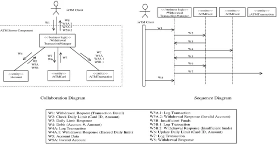
Figure 1 describes a partial collaboration diagram and one sequence dia-gram of an ATM server component. The sequence diadia-gram only shows one of the possible scenarios ordered by time while the collaboration combines all sce-narios in numbered order. In Figure 1, W5, W5A, and W5B demonstrate three alternatives that can occur after the message W4 is passed by the Withdrawal Transaction Manager object to the ATM Account object.
With the collaboration diagrams, we can refine our context-dependence re-lationships to be all possible sequences, as shown in Figure 1 in a collaboration
<<entity>> :Account << business logic>> :Withdrawal TransactionManager <<entity>> :ATMTransaction <<entity>> :ATMCard W1 W4A.1 W8 W5A.2 W5B.2 W4 W5 W5A W5B W2 W6 W3 W7 W4A W5A.1 W5B.1 ATM Server Component
:ATM Client <<entity>> :ATMCard << business logic>> :Withdrawal TransactionManager <<entity>> :ATMTransaction <<entity>> :ATMCard W1 W4 W2 W3 :ATM Client W5 W6 W7 W8
Collaboration Diagram Sequence Diagram
W1: Withdrawal Request (Transaction Detail) W2: Check Daily Limit (Card ID, Amount) W3: Daily Limit Response
W4: Debit (Account #, Amount) W4A: Log Transaction
W4A.1: Withdrawal Response (Exceed Daily limit) W5: Account Data
W5A: Invalid Account
W5A.1: Log Transaction
W5A.2: Withdrawal Response (Invalid Account) W5B: Insufficient Funds
W5B.1: Log Transaction
W5B.2: Withdrawal Response (Insufficient funds) W6: Update Daily Limit (Card ID, Amount) W7: Log Transaction
W8: Withdrawal Response
Fig. 1.Collaboration and Sequence Diagrams of an ATM Server Component
diagram that could be possibly invoked to precisely model how interfaces and events interact with each other.
2. Statechart based approach.
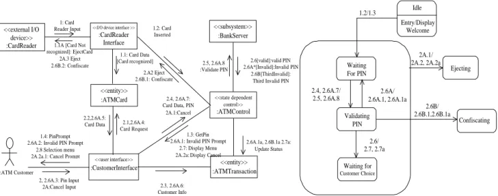
The collaboration diagram itself is not always sufficient to model behaviors of the interactions of components. The behavior of a component can be more precisely modeled by combining the collaboration diagram with statechart dia-grams, which are used to describe state-dependent control objects in components. For example, Figure 2 shows a collaboration diagram and statechart. As we can see, the sequence “2A - 2A.1 - 2A.2, 2A.2a - 2A.3, 2A.2a.1” (2A.2 and 2A.2a are two concurrent messages) is the only sequence that allows the user to cancel. Nevertheless, this sequence can happen in different contexts, such as the user canceling the current transaction after correctly inputting the PIN, or the user canceling the current transaction after incorrectly inputting the PIN. With the help of the statechart diagram, which is shown in Figure 2(b), we can clearly see that the cancelation sequence needs to be validated in three different scenarios: (1) Waiting for PIN, (2) Validating PIN and (3) Waiting for Customer Choice.
The interactions among interfaces and events can be further refined by using the statechart diagram. Given a statechart diagram, our context-dependence re-lationships will have to include not only all possible sequences in a collaboration diagram, but all possible combinations of the sequences that are shown in the statechart diagram as well.
<<entity>> :ATMCard <<I/O device interface >>
:CardReader Interface <<user interface>> :CustomerInterface <<state dependent control>> :ATMControl <<entity>> :ATMTransaction <<subsystem>> :BankServer <<external I/O device>> :CardReader 1: Card Reader Input 1.1: Card Data [Card recognized] 1.1A [Card Not
recognized]: EjectCard 2A.3 Eject 2.6B.2: Confiscate 1.2: Card Inserted 1.3: GetPin 2.6A.1: Invalid PIN Prompt
2.7: Display Menu 2A.2a: Display Cancel
:ATM Customer
1.4: PinPrompt 2.6A.2: Invalid PIN Prompt
2.8 Selection menu 2A.2a.1: Cancel Prompt
2, 2.6A.3: Pin Input 2A:Cancel Input 2.1,2.6A.4: Card Request 2.2,2.6A.5: Card Data 2.3, 2.6A.6: Customer Info 2.4, 2.6A.7: Card Data, PIN
2A.1:Cancel 2.5, 2.6A.8 :Validate PIN 2.6[valid]:valid PIN 2.6A*[Invalid]:Invalid PIN 2.6B[ThirdInvalid]: Third Invalid PIN
2.6A.1a, 2.6B.1a 2.7a: Update Status 2.A2 Eject 2.6B.1: Confiscate Idle Entry/Display Welcome Waiting For PIN Validating PIN Waiting for Customer Choice Ejecting Confiscating 1.2/1.3 2.4, 2.6A.7/ 2.5, 2.6A.8 2.6A/ 2.6A.1, 2.6A.1a 2.6/ 2.7, 2.7a 2A.1/ 2A.2, 2A.2a 2.6B/ 2.6B.1,2.6B.1a
Fig. 2.Collaboration Diagram and Statechart for Validate PIN
Content-dependence relationships Context-dependence relationships reflect
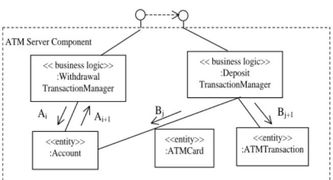
control sequences of objects in a component with respect to single interactions between actors and the component. Nevertheless, content-dependence relation-ships among different interactions cannot be obtained solely from control flow information. For example, consider Figure 3, which shows an extended ATM server component. The component includes two interfaces - withdraw and de-posit. Context dependence relationships may depict the interactions within each interface, but the content-dependence relationships across the interfaces cannot be obtained. For instance, the withdrawal interface depends on deposit inter-face because the deposit transaction will modify the account entity, while the withdrawal transaction will use that entity to verify whether there is enough money in that account. Unfortunately, content-dependence relationships are not directly specified either in the program or in any UML diagrams. To specify the content-dependence relationships, further processing of UML diagrams is necessary. We suggest two approaches below.
1. Collaboration diagram approach.
UML collaboration diagrams and sequence diagrams demonstrate interactions of objects within a component. When interactions involve entity classes, col-laboration diagrams can demonstrate the dependence relationships between two interactions. For example, Figure 3 shows messageBj flowing into entity class
mes-<<entity>> :Account << business logic>> :Withdrawal TransactionManager <<entity>> :ATMTransaction <<entity>> :ATMCard ATM Server Component
<< business logic>> :Deposit TransactionManager Bj Ai+1 Ai Bj+1
Fig. 3.An Extended ATM Server Component
sage Bj will update information in Account objects. We define this to be an
update message. On the other hand, messages Ai and Ai+1 flow into and out ofAccount, which indicates that information ofAccountis retrieved. These are called retrievemessages. Therefore, interactions that include messages Ai and
Ai+1will depend on sequences that includes messageBj. In general, an interface
Idependson interfaceI0 if and only if a message sequence invoked byI includes anupdatemessage, and another sequence invoked byI0includes a corresponding
retrievemessage.
2. Statechart diagram approach.
Statechart diagrams can demonstrate content dependence relationships from a state transition point of view. The rationale lies in the fact that if interface I1 depends onI2, the state of the component isS1 after the execution ofI1. When executing interface I2, the state transitions fromS1 to S2 depend on state S1 and the invocationI1. To model this type of content dependence relationships, we eliminate dependence relations that are not effective:
– If the component remains in the original state S1 after the invocation of
I1, the dependence relationship does not affect the behavior of the software; therefore the dependence relationship is not effective.
– From a stateS, if the invocation ofI2 will always bring the state toS
0
, it does not matter if interface I1 is invoked before I2 or not. This indicates that the state transformation is not caused by the dependence relationships.
UML-based test adequacy criteria Given the UML-based context
depen-dence relationships and content dependepen-dence relationships, the test criteria that were provided in our test model has to be modified follows:
1. Each transition in each collaboration diagram has to be tested at least once. 2. Each valid sequence in each collaboration diagram has to be tested at least
once.
3. Each transition in each statechart diagram has to be tested at least once. 4. Each content-dependence relationship derived from each collaboration
5. Each effective content-dependence relationship derived from each statechart diagram has to be tested at least once.
4
Related Work
The research results in this paper follow a small but growing body of work in component-based software testing. Weyuker [16] developed a set of axioms to help determine test adequacy and used them to evaluate several program-based testing techniques. Perry and Kaiser [14] further applied these adequacy axioms to oriented software and suggested that in the presence of object-oriented features, in particular inheritance and multiple inheritance, subclasses and superclasses require special attention during testing. Stemming from these studies, we developed a class testing technique [6] for testing object-oriented classes and programs.
In component-based testing, Rosenblum [15] proposed a formal model for ad-equate testing of component-based software, in which a “C-adequate” criterion is defined to determine the adequacy of a test set for a given component-based software system as well as for a single component. A number of concepts [8, 9, 18] have been proposed to analyze the characteristics of component-based soft-ware and suggest ways to test component-based systems. Harrold et al. [9] pro-posed a testing technique that is based on analysis of component-based systems from component-provider and component-user perspectives. The technique was adapted from an existing technique [10], which makes use of complete informa-tion from components for which source code is available and partial informainforma-tion from those for which source code is not available. They further extended their work by proposing a framework that lets component providers prepare various types of metadata such as program slicing [13]. The metadata was then used to help test component-based systems. Ghosh and Mathur [8] discussed issues in testing distributed component-based systems and suggested an interface and exception coverage-based testing strategy.
The UML is increasingly being used to support the design of component-based systems [5, 11]. Some of the UML diagrams have also been used to auto-matically generate test cases. Offutt and Abdurazik first proposed a mechanism that adapted state specification-based test data generation criteria to generate test cases from UML statecharts [12]. They subsequently extended their work to generate tests from UML collaboration diagrams [1]. Similarly, Briand and Labiche suggested using class diagrams, collaboration diagrams, or OCL to de-rive test requirements[3].
5
Conclusions and Future Work
This paper has presented a new model for describing component-based software and a related approach for testing. The model uses different UML diagrams to model the internal behavior of third party software components. When the source is not available (as is usually the case), these behavioral descriptions
can be used as a basis for deriving tests that can help ensure the quality of the component-based system. Our ongoing research directions on this topic are empirical studies of comparisons of the effectiveness of our approach with other approaches, the development of a tool to support automation of the technique, and enhancement of the technique for resolving problems caused by distributed characteristics such as synchronization.
References
1. Aynur Abdurazik and Jeff Offutt. Using UML collaboration diagrams for static
checking and test generation. In Third International Conference on the Unified
Modeling Language (UML ’00), pages 383–395, York, UK, October 2000.
2. Paul Allen. Component-based development for enterprise systems: Applying the
SELECT Perspective. Cambridge, UK, New York: Cambridge University Press, 1998.
3. Lionel Briand and Yvan Labiche. A UML-based approach to system testing. In
Fourth International Conference on the Unified Modeling Language (UML ’01), pages 194–208, Toronto, Canada, October 2001.
4. Alan W. Brwan. Background information on CBD. SIGPC, 18(1), August 1997.
5. John Cheesman and John Daniels. UML components : A simple process for
speci-fying component-based software. Addison-Wesley, 2001.
6. M. Chen and M. Kao. Effect of class testing on the reliability of object-oriented
programs. InProceedings of the Eighth International Symposium on Software
Re-liability Engineering, May 1997.
7. Szyperski Clemens. Component Software: Beyond Object-oriented Programming.
Addison-Wesley, 1998.
8. S. Ghosh and A. P. Mathur. Issues in testing distributed component-based systems. In First International ICSE Workshop on Testing Distributed Component-Based Systems, Los Angeles, 1999.
9. M. J. Harrold, D. Liang, and S. Sinha. An approach to analyzing and testing
component-based systems. InFirst International ICSE Workshop on Testing
Dis-tributed Component-Based Systems, Los Angeles, 1999.
10. M. J. Harrold and G. Rothermel. Performing dataflow testing on classes. In
Proceedings of the Second ACM SIGSOFT Symposium on Foundations of Software Engineering, pages 154–163, December 1994.
11. George Heineman and William Councill. Component-based software engineering :
Putting the pieces together. Addison-Wesley, 2001.
12. Jeff Offutt and Aynur Abdurazik. Generating tests from UML specifications. In
Second International Conference on the Unified Modeling Language (UML ’99), pages 416–429, Fort Collins, CO, October 1999. IEEE Computer Society Press. 13. Alessandro Orso, Mary Jean Harrold, and David Rosenblum. Component metadata
for software engineering tasks. InProceedings of the 2nd International Workshop
on Engineering Distributed Objects (EDO 2000), pages 126–140, November 2000. 14. D. E. Perry and G. E. Kaiser. Adequate testing and object-oriented programming.
Journal of Object-Oriented Programming, Jan. 1990.
15. D. S. Rosenblum. Adequate testing of component-based software. Technical Report TR97-34, University of California at Irvine, 1997.
16. E. J Weyuker. Axiomatizing software test data adequacy. IEEE Transactions on
17. E. J Weyuker. Testing component-based software: A cautionary tale. IEEE
Soft-ware, 15(5):54–59, September/October 1998.
18. Ye Wu, Dai Pan, and Mei-Hwa Chen. Techniques for testing component-based
soft-ware. In7th IEEE International Conference on Engineering of Complex Computer