RESEARCH DISSERTATION FOR:
Development of Thick Section Friction Stir Welding Using a
Sliding Tool Shoulder
By:
Shamalin Chetty
Submitted in fulfilment of the requirements for the degree of
Magister Technologiae: Engineering Mechanical at the Nelson
Mandela Metropolitan University
April: 2013
Supervisor: Prof DG Hattingh
i Copyright © 2013 Nelson Mandela Metropolitan University
ii
I,
Shamalin Chetty 20318222, hereby declare that the dissertation for Magister Technologiae: Mechanical Engineering is my own work and that it has not previously been submitted for assessment or completion of any postgraduate qualification to another University or for another qualification.
iii
Abstract
Development of Thick Section Friction Stir Welding Using a Sliding Tool Shoulder S. Chetty
Faculty of Engineering, the Built Environment and Information Technology Nelson Mandela Metropolitan University
PO BOX 77000, Port Elizabeth, South Africa
Dissertation: Magister Technologiae: Engineering: Mechanical 2013
Sliding shoulder friction stir welding (SSFSW) is an alternative joining technique to the conventional friction stir welding process. The welding mechanism comprises of a rotating probe and a non-rotating shoulder. The shoulder therefore does not contribute to any heat generation or plastic deformation. When welding thicker section material, the contribution of heat generation from the shoulder becomes less significant and most of the heat and plastic deformation must be generated by the tool probe. For this reason it was decided to develop the process for thick section AA6082-T6. Due to the stationary (non-rotating) shoulder the weld track is smooth and there is no reduction in cross-sectional area. This research is based on the development of a sliding shoulder friction stir welding tool with the ability to create joints of up to 25mm thick on aluminium alloy 6082-T6 plate as well as the associated process development. The sliding shoulder friction stir welding tool was designed, manufactured and tested by initially performing partial penetration welds with various size tool probes and then finally by performing a sliding shoulder friction stir butt weld on 25mm thick plate. As welds were performed and more knowledge gained about the process, design modifications were made. These included varying the clearance between the tool probe and stationary shoulder; the profile of the shoulder which contributes to material
iv welding thicker sections at high forge forces. From the sliding shoulder friction stir welds performed, an understanding of material flow during the process was gained when analysing the macro-sections and exit holes of the welds. Typical process forces and torques associated with the process were measured to assist with future head unit and tool designs with regard to sliding shoulder friction stir welding.
v
Acknowledgements
First and fore mostly I would like to thank the late Dr Calvin Blignault whom I initially started the research topic with. I would also like to thank all my family, friends, fellow researchers, my promoter and all staff who assisted me with my research at the NMMU Mechanical Engineering Department. Special thanks must also go to the NRF and NMMU RCD.
vi : Introduction ... 1 Chapter 1 1.1) Conventional FSW ... 1 1.2) Sliding Shoulder FSW ... 3 1.3) Problem Statement ... 4 1.3.1) Sub-Problems ... 4 1.4) Hypothesis ... 5 1.5) Research Methodology ... 5
1.6) Delimitation of the Research ... 6
1.7) Significance of the Research ... 7
1.8) Feasibility and impact of the proposed research ... 7
: Literature Review ... 9 Chapter 2 2.1) Introduction ... 9 2.2) Tool Design ... 10 2.2.1) Tool Material... 12 2.3) Welding Parameters ... 13 2.4) Heat Generation ... 14 2.5) Material Flow ... 15 2.6) Weld Zones ... 17 2.7) Defects ... 18
2.8) Sliding Shoulder Friction Stir Welding ... 20
2.9) Summary ... 21
: Development of the SSFSW Tool ... 23
Chapter 3 3.1) Introduction ... 23
3.2) Welding Material ... 23
3.3) MTS I-Stir PDS Platform ... 25
3.4) Conventional Friction Stir Welding ... 25
3.5) Experimental Setup ... 26
3.5.1) Axis Orientations ... 26
3.5.2) Conventional FSW Clamping Mechanism and Backing Plate ... 27
3.6) Conventional Friction Stir Welds ... 27
3.6.1) Bead on Plate Welds ... 28
vii
3.7) Static Strength Testing ... 34
3.8) Sliding Shoulder Friction Stir Welding Head Unit ... 36
3.9) Tool Probe Designs ... 39
3.10) Tool Shoulder Design ... 40
3.11) Summary of SSFSW Tool Development ... 41
: Process Development of SSFSW ... 42
Chapter 4 4.1) Introduction ... 42
4.2) Probe – Tool Shoulder Clearance Test ... 42
4.3) Welding Procedure ... 43
4.4) Partial Penetration Bead on Plate SSFSW ... 44
4.4.1) Experimental Setup ... 44
4.4.2) W-1 (Tool 2) – 14mm Penetration on 25mm plate ... 45
4.4.3) Material Flow under Shoulder ... 47
4.4.4) W-2 (Tool 2) - 14mm Penetration on 25mm plate ... 48
4.4.5) W-3 (Tool 2) - 14mm Penetration on 25mm plate ... 50
4.4.6) W-4 - 14mm Penetration (Tool 2) ... 52
4.4.7) W-5 - 14mm Penetration (Tool 2) ... 53
4.4.8) Comparison of torque data ... 55
4.4.9) Comparison of Calculated Heat Generation ... 56
4.4.10) W-6 - 20mm Penetration (Tool 3) ... 56
4.4.10.1) SSFSW Tool Design Modification ... 59
4.4.11) W-7- 20mm Penetration ... 59
4.5) Conclusions from Partial Penetration SSFSW... 62
4.6) SSFSW Butt Welds ... 62
4.6.1) Experimental Setup of Butt Welds ... 63
4.6.2) W-8... 64
4.6.2) W-9... 71
4.6.3) W-10 ... 75
4.7) SSFSW - Weld Surface ... 79
4.8) SSFSW Material Flow ... 79
4.9) Summary of Process Development ... 81
: Discussion of Results ... 83
Chapter 5 5.1) Introduction ... 83
5.2) Comparison of SSFSW Torque Data ... 83
viii
5.6) Summary of Results ... 86
: Conclusions and Future Work ... 87
Chapter 6 Appendix A ... 90
References ... 112
List of Figures
Figure: 1-1 - FSW Schematic [1] ... 2Figure: 1-2 - Advancing and Retreating Side ... 2
Figure: 1-3 - Schematic of the Sliding Shoulder FSW Process ... 3
Figure: 2-1 - FSW Joint Types [3] ... 9
Figure: 2-2 - Tool Probe Designs ... 11
Figure: 2-3 - Whorl and MX Triflute tools [3] ... 12
Figure: 2-4 - Advancing and Retreating Side [3] ... 15
Figure: 2-5 - Material Flow [5] ... 16
Figure: 2-6 - a) Pin-Driven Flow b) Combined Flow [9] ... 17
Figure: 2-7 - Weld Zones [10] ... 17
Figure: 2-8 - Volumetric Defects [10] ... 18
Figure: 2-9 - Joint Line Defects [10] ... 19
Figure: 2-10 - Root Flaw [10] ... 19
Figure: 2-11 - Defect Table [10] ... 20
Figure: 2-12 – Smooth Weld Surface of Fixed Shoulder FSW [14] ... 21
Figure: 2-13 – Fixed Shoulder FSW Macro [14] ... 21
Figure: 3-1 - The MTS I-Stir PDS FSW Platform ... 25
Figure: 3-2 - Conventional FSW Tool with probe as insert ... 26
Figure: 3-3 - Clamping Mechanism and Backing Plate ... 27
Figure: 3-4 – Bead on Plate FSW 1 Force and Torque Response ... 28
Figure: 3-5 – Bead on Plate FSW 2 Force and Torque Response ... 29
Figure: 3-6 - Conventional Butt Weld1 Surface ... 30
Figure: 3-7 - Conventional Butt Weld 1 Macro- Section ... 31
Figure: 3-8 - Conventional FSW Butt Weld 1 Force and Torque Responses ... 32
Figure: 3-9 - Conventional Butt Weld 2 Surface ... 33
Figure: 3-10 - Conventional FSW Butt Weld 2 Shoulder Position Feedback ... 33
Figure: 3-11 – Conventional FSW Butt Weld 2 Force and Torque Responses ... 33
Figure: 3-12 - Conventional Butt Weld 2 Macro ... 34
Figure: 3-13 - Tensile Testing Results ... 34
Figure: 3-14 - Fracture Locations ... 35
Figure: 3-15 - The SSFSW Head Unit Mechanism Schematic ... 36
Figure: 3-16 - SSFSW Head Unit ... 38
Figure: 3-17 - Tool Probe Schematic ... 40
Figure: 4-1 - Setting of Probe Length ... 43
Figure: 4-2- SSFSW BOP Clamping... 44
Figure: 4-3 - W-1 Weld Surface ... 45
Figure: 4-4- W-1 Force and Torque Response... 46
ix
Figure: 4-6 - W-1 Forge Position Feedback ... 47
Figure: 4-7 - Material Flow under Shoulder ... 48
Figure: 4-8 - Tool Shoulder Modification ... 48
Figure: 4-9 - W-2 Weld Surface ... 49
Figure: 4-10 - W-2 Macro-Section ... 49
Figure: 4-11 - W-2 Force and Torque Response ... 50
Figure: 4-12 - W-3 Top View ... 50
Figure: 4-13 - W-3 Force and Torque Response ... 51
Figure: 4-14 - W-3 Macro-Sections ... 51
Figure: 4-15 - W-4 Weld Surface ... 52
Figure: 4-16 - W-4 Force and Torque Response ... 52
Figure: 4-17 - W-4 Macro-Section ... 53
Figure: 4-18 - W-5 Weld Surface ... 53
Figure: 4-19 - W-5 Force and Torque Response ... 54
Figure: 4-20 - W-5 Macro-Sections ... 54
Figure: 4-21 - 15mm Penetration Torque Data ... 55
Figure: 4-22 - Calculated Heat Generation (15mm Penetration) ... 56
Figure: 4-23 – W-6 Weld Surface ... 57
Figure: 4-24 – W-6 Force and Torque Response ... 58
Figure: 4-25 – W-6 Weld Macro ... 58
Figure: 4-26 – W-6 Tool Wear ... 58
Figure: 4-27 - SSFSW Tool Design Modification ... 59
Figure: 4-28 – W-7 Weld Surface ... 60
Figure: 4-29 – W-7 Force and Torque Response ... 60
Figure: 4-30 - Tool Shoulder Deformation ... 61
Figure: 4-31 - Tool Pin ... 61
Figure: 4-32 – W-7 Weld Macro ... 61
Figure: 4-33 - Testing Sample Layout Diagram ... 63
Figure: 4-34 - Butt Weld Clamping ... 63
Figure: 4-35 - Tool Shoulder before Welding ... 64
Figure: 4-36 - Tool Shoulder after Welding ... 65
Figure: 4-37 - Tool Shoulder Inside after Welding ... 65
Figure: 4-38 - Bearing after Welding ... 65
Figure: 4-39 – W-8 Weld Surface ... 66
Figure: 4-40 – W-8 Force and Torque Response ... 67
Figure: 4-41 – W-8 Macro ... 67
Figure: 4-42 – W-8 Onion Ring Patterns ... 68
Figure: 4-43 – W-8 Bend Test ... 68
Figure: 4-44 - W-8 Forge Position ... 69
Figure: 4-45 - W-8 Ultimate Tensile Strength ... 70
Figure: 4-46 – W-8 T4 Specimen Fracture Location ... 70
Figure: 4-47 – W-8 Vickers Hardness ... 70
Figure: 4-48 - W-9 Weld Surface ... 71
Figure: 4-49 - W-9 Force and Torque Response ... 72
Figure: 4-50 - W-9 Macro ... 72
Figure: 4-51 - W-9 Weld Root ... 73
Figure: 4-52 – W-9 Forge Position Feedback ... 73
Figure: 4-53 - W-9 Ultimate Tensile Strength ... 74
Figure: 4-54 - W-9 Vickers Hardness ... 74
Figure: 4-55 - W-10 Weld surface ... 75
Figure: 4-56 - W-10 Weld Surface Close-up ... 75
Figure: 4-57 W-10 Force and Torque Response ... 76
x
Figure: 4-61 - W-10 Forge Position Feedback ... 78
Figure: 4-62 - W-10 Vickers Hardness ... 78
Figure: 4-63 - SSFSW Weld Surface and FSW Weld Surface ... 79
Figure: 4-64 - SSFSW Material Flow around Probe ... 80
Figure: 4-65 - Deflection of Probe ... 80
Figure: 4-66 - Evidence of Probe Interference ... 80
Figure: 4-67 - Material Flow in front of the Tool Pin ... 81
Figure: 5-1 - Butt Weld Torque Data ... 83
Figure: 5-2 - Calculated Heat Generation (Butt Welds) ... 84
Figure: 5-3 - Forge Positions (Butt Welds) ... 85
Figure: 5-4 - Butt Weld Tensile Data ... 86
List of Tables
Table 1: Tested VS Standard Chemical Composition ... 24Table 2: Tested Mechanical Parent Plate Properties ... 24
Table 3: Typical Physical Properties [15] ... 25
Table 4: Tool Pin Dimension ... 39
Table 5: Tools Shoulder Dimensions ... 40
xi
Glossary of Terms
Advancing Side Side where the direction of rotation is the same as the welding direction
Alloy Mixture of two or more metals
Ambient Temperature Temperature of the surrounding area Base Material Area of material not affected by the weld Butt Joint A joint between two members lying
approximately in the same plane
Defect An imperfection in the weld
Ductility A mechanical property used to describe the extent to which materials can be deformed plastically without fracture
Elevated Temperature Increased temperature
Flaw An acceptable imperfection in the weld
FPRI Friction Process Research Institute
Fracture Toughness A property which describes the ability of a material containing a crack to resist fracture
FSW Friction Stir Welding
HAZ Heat Affected Zone
Homogenous Consisting of the same kind
HRS-FSW High Rotation Speed Friction Stir Welding Isotropic Having the same physical properties in all
directions
xii by a microscope above 25× magnification
Oxide A binary compound of oxygen
Pilot Hole A hole drilled into the plate(s) to be welded prior to welding for the tool pin to plunge into
Plastic Deformation The deformation of a material undergoing non-reversible changes in shape in response to an applied force
Retreating Side Side where the direction of rotation is opposite to the welding direction
SSFSW Sliding Shoulder Friction Stir Welding Thermal Gradient The dispersion of heat across a profile
Thick Section Weld Welded plates of thickness greater than 16mm
TMAZ Thermo-Mechanical Affected Zone
Traverse Forward Motion
Truncated Tool Tool with a tapered profile Vortex Current A whirling force
Weld Nugget Re-crystallized region of the TMAZ
Weld Track Top Surface of the weld when the shoulder slides across it
1
: Introduction
Chapter 1
1.1)
Conventional FSW
Friction stir welding (FSW) is a process where a tool, which comprises a probe and shoulder, is utilised to generate frictional heat between the tool and the work pieces to be joined. During the FSW process the tool shoulder and probe rotate together at the same rotational speed. This heat plasticises material around the tool probe to allow for mixing and the creation of a metallurgical bond. The tool shoulder prevents material from flowing out of the weld zone and provides a forging force to assist with consolidation of the weld. The melting temperature of the material is not reached, making FSW a solid-state joining process, where material is forged together as opposed to conventional welding techniques where the material is cast. In conventional FSW the tool is first rotated to a pre-determined speed, plunged into the plates and then traversed along the joint line. Typically the weld process consists of a series of operations namely; plunge-in, dwell period, weld ramp-up, maximum weld traverse rate, ramp down and tool extraction. However not all of these are always fully exploited. The three primary process parameters that are known to affect the quality of friction stir welds are; tool rotational speed, traverse (feed) speed and downward (forge) force. Figure: 1-1 shows a schematic of the conventional friction stir welding process indicating the tool probe and shoulder as well as the tool rotation, feed and applied forge force.
2
Figure: 1-1 - FSW Schematic [1]
The asymmetric nature of the FSW process results in an uneven heat distribution and material flow path within the weld nugget, which can lead to variation in the weld properties on either side of the joint line. The advancing side (AS) of the weld is where the direction of tool rotation is the same as the welding direction, while the other side is designated as the retreating side (RS) as indicated in Figure: 1-2. For example the hardness of particular age hardened aluminium alloys tends to be lower on the advancing side than on the retreating side, which then becomes the location of tensile fracture in cross weld tests [2,3].
Figure: 1-2 - Advancing and Retreating Side
Direction of Tool Rotation
Traverse Direction
Advancing Side
Retreating Side Tool
Chapter 1 Introduction
3
1.2)
Sliding Shoulder FSW
Sliding shoulder friction stir welding (SSFSW) is an alternative friction stir welding technique where the pin of the tool rotates independently of the shoulder. The shoulder of the tool does not rotate during welding; it slides on top of the material surface as shown in Figure: 1-3. In this configuration it does not contribute to any heat generation but only contains the plastic flow of material within the weld zone to prevent void formation and inconsistent consolidation. Heat is only generated by friction between the tool probe and the material in contact with it.
Figure: 1-3 - Schematic of the Sliding Shoulder FSW Process
When the FSW process is used for joining thicker section material, the contribution of the heat generated by the shoulder becomes less significant towards the root of weld where the heat required to plasticise the material must be generated by the tool probe. The SSFSW process is therefore ideal for the joining of thicker section material, as by using a sliding shoulder it is possible to obtain a more linearly distributed heat flow in the weld region due to the tool pin generating all the heat, as well as a smoother surface appearance, with no reduction in cross-section.
Rotating Tool
Joint Line
Sliding Shoulder
Tool Probe Smooth Weld Surface
4
1.3) Problem Statement
To develop a sliding shoulder friction stir welding processing tool and demonstrate the tool on 25mm thick AA6082-T6 by means of the sliding tool shoulder technique.
1.3.1) Sub-Problems
Design and manufacture of a SSFSW Tool and Shoulder Mechanism:
An innovative welding processing tool will need to be designed and manufactured, since the current equipment does not have the capability to friction stir weld with a sliding shoulder.
A thorough assessment of the structural design will be required to ensure the strength and loading capacity of the SSFSW mechanism.
The SSFSW mechanism will be integrated into the existing MTS ISTIR Platform.
Design of experimental set-up
An experimental set-up will need to be designed; which will include secondary systems such as clamping and backing support.
Development of process parameters for evaluating SSFSW
There is no literature available on the welding of thick section material by means of a sliding tool shoulder.
The process parameters and operating window will need to be evaluated experimentally.
Chapter 1 Introduction
5 Optimisation of process parameters for successful SSFSW of AA-6082
Selective weld parameter settings established will be repeated with the aim of further improving weld quality and joint strength.
Analysis of results
Results will be analysed and conclusions will be drawn based on scientific evidence in order to evaluate the feasibility of SSFSW.
Bead on plate welds will be assessed by visual inspection of the surface quality and macro-section evaluation.
Butt welds will be assessed by visual inspection of the surface quality, macro-section evaluation and static testing.
1.4) Hypothesis
Sliding shoulder friction stir welds with mechanical properties comparable to conventional friction stir welds can be produced in thick section aluminium alloys using a non-rotating tool shoulder.
1.5) Research Methodology
The plan of action for this research project is as follows:
Literature research of FSW, SSFSW, AA-6082 and any other relevant information in order to understand the process and material involved.
Design of a Conventional FSW tool for welding 25mm thick plate
6 Design and development of a novel friction stir welding mechanism to allow for
welding to be made with a sliding tool shoulder Design of SSFSW tool probe(s).
Procurement of materials including those used for the fabrication of the welding mechanism.
Pilot trial partial penetration bead on plate welds to determine the initial parameters and limits of the processing tool, which will be used to set-up parameters for butt welds.
Butt welds of 25mm thick AA6082-T6 plate.
Selected welds will be sectioned and assessed to determine mechanical properties. This will include but not be limited to macro-sections, hardness measurement as well as tensile and bend testing to better characterise weld integrity.
All relevant results will then be documented and final conclusions drawn.
1.6) Delimitation of the Research
The research is limited to AA-6082-T6 with a maximum plate thickness of 25mm. Parameters will be limited to the capabilities of the SSFSW mechanism.
Probe rotation speed and forge force will be varied with the rest of the process parameters fixed.
Due to financial constraints only a limited amount of experiments will be conducted to characterise weld quality
Chapter 1 Introduction
7
1.7) Significance of the Research
The research will establish the feasibility of the process as an alternative technique for joining thick section AA6082-T6 plate. One of the main advantages of SSFSW is that a uniform thermal gradient can be generated throughout the weld thickness. The heat is generated and focused on a smaller area, reducing the weld Heat Affected Zone (HAZ). More control over the process heat input is possible. In addition a very smooth weld track surface is produced when using a sliding shoulder that does not rotate with the tool. Some of the major benefits that SSFSW may provide are:
A new welding approach capable of reliably producing high quality solid-phase welds in a wide range of material combinations.
Production of reliable welds with excellent surface finish and no reduction in cross-section.
Improved control of process heat input to provide a high efficiency, low energy consuming welding technique.
Improved flexibility for applications via enhanced process stability and reduced shoulder reaction forces.
1.8) Feasibility and impact of the proposed research
The feasibility of the concept has been proven but very little literature is available on SSFSW with respect to thick section materials, and therefore further work is required in this field. The research results will contribute to FSW processing knowledge within the field. Currently very little to no reduction in welding thickness can be obtained when compared to traditional friction stir welding. Knowledge and know-how from the
8 proposed research could be adapted to suit high temperature strength alloy welding, such as Titanium or Nickel based alloys as well as to various weld joint profiles such as corner fillet welds, pipes and other complex joint geometries. Post welding machining costs can be significantly reduced since this method produces a very smooth surface finish which does not require post-weld machining.
9
: Literature Review
Chapter 2
2.1) Introduction
FSW is viewed as a major development in solid state welding, where no melting of the parent material occurs. It is considered to be an environmentally friendly process as it is more energy efficient than conventional welding processes. The FSW process can be used to join dissimilar as well as materials which cannot be joined by conventional welding processes. Joint types which are possible using the FSW process include, but are not limited to; Butt, Lap, T-Butt joints as well as Fillet welds [3,4].
Figure: 2-1 - FSW Joint Types [3]
Traditional FSW is a process where a rotating tool, which consists of a cylindrical shoulder and a smaller diameter probe, is forced along a joint line between two abutting plates. An alternative to conventional FSW is Sliding Shoulder Friction Stir Welding (SSFSW), where the small diameter probe rotates and the shoulder does not. At optimal input parameters, enough frictional heat is generated to raise the temperature of the material to a state in which it can be easily plastically deformed, stirred by the tool probe and contained by the tool shoulder. When analysing the conventional FSW process the major aspects that need to be understood are tool design, influence of process parameters, material flow, weld zones and the formation of defects.
10
2.2) Tool Design
The design of the tool shoulder and probe has a major influence on the generation of heat, plastic flow of material, forces and torque involved during the FSW process. Tool profiles generally consist of a shoulder and a probe. The probe stirs the material while the shoulder compresses the surface of the workpiece and contains the softened weld material, preventing void formation [2,3]. Heat is generated on the surface by friction between the rotating shoulder and the workpiece surface and when welding thin sheets, this is the main source of heat input [5]. However, as the workpiece thickness increases, more heat must be supplied by the friction between the rotating probe and the workpiece, as the heat generated by the shoulder is not sufficient to plasticise material through the entire plate thickness [5]. In addition to this, the main function of the probe is to ensure sufficient working of the material at the weld line and to control the flow of the material to produce a weld of satisfactory quality as the weld progresses. The probe also breaks and disperses oxides and other impurities from the joint line [3,5]. Both shoulder and probe are generally profiled and the probe is usually threaded to facilitate the dispersal of these oxides and other impurities, the threading of the probe increases the surface area which in turn increases frictional heat generation during the process. There are many different tool probe profiles in use, some of which can be seen in Figure: 2-2. They range from cylindrical threaded probes to other tool profiles such as truncated probes, with some including a combination of thread, flats or flutes such as the Triflute and Triflat tools developed by TWI [6].
Chapter 2 Literature Review
11
Figure: 2-2 - Tool Probe Designs
The truncated tools have smaller tool probe core volumes and a greater surface area than cylindrical tool probes; their profiles induce greater stirring and reduce process reaction forces. When friction stir welding thicker section material, it is important to use tool probes which are truncated with either grooves or flats as these tools provide additional heat generation deep in the weld away from the influence of the shoulder [3,6]. The fluted truncated tool probes with deep helical grooves machined into them assist with vertical movement of the plasticised material [3,6]. These truncated tool probes with flats or grooves are generally used when welding thicker sections as they produce a less aggressive stirring action and result in reduced process forces. Tools with flats are generally stronger than tools with flutes due to the increased core volume [3,6]. Truncated tools such as the Whorl and MX-Triflute tools(Figure: 2-3); displace less material than cylindrical tools of the same root diameter, reduce welding process forces, enable easier flow of plasticised material, facilitate the downward flow of plasticised material and increase the interface between the probe and plasticised material which increases heat generation [7].
12
Figure: 2-3 - Whorl and MX Triflute tools [3]
Investigations by K. A. Beamish et al [6] using Triflute and Triflat tools show that: Torque decreases with increasing tool rotation speed for a given forward
movement per revolution.
Torque increases with increasing traverse rate at constant tool rotation.
Tool temperatures are roughly constant for a given forward movement per revolution (mm/rev).
Tool temperatures decrease with increasing forward movement per revolution. Required forge force increases with increasing forward movement and
decreases with decreasing rotation speed.
2.2.1) Tool Material
Many material characteristics need to be considered when selecting tool material as the tool needs to be able to withstand the forces and torques exerted during the
Chapter 2 Literature Review
13 welding process at elevated temperatures; the material should therefore be able to maintain its properties at these elevated temperatures. The tool should be resistant to wear so as not to lose its profile, as this has a major effect on weld quality, reproducibility and tool life. Fracture toughness is an important factor during the start of the weld as the material is still cold and high stresses are exerted on the tool during the plunge, dwell and initial traverse of the tool. The material should be easy to machine as features may need to be machined into the tool probe and if the tool material is not homogenous certain areas will be weaker than others which will lead to tool failure [8]. From previous literature, for aluminium alloys less than 12mm thick a suitable tool material is Tool Steel (W302) and for thicker section less than 40mm, MP159 is generally used [8].
2.3) Welding Parameters
Process input variables have a major influence on the joint integrity. Joint profile, microstructure and mechanical properties are all governed by the process parameters. Tool rotation speed and tool traverse rate are critical input parameters as these directly influence heat generation and the mixing of the weld material. The forge force assists in the consolidation of the weld and maintains contact between the tool shoulder and the weld material while the depth of insertion of the tool probe into the material is another parameter that influences weld quality; this parameter is often referred to as plunge depth. It is dependent on the length of the tool probe. If the plunge depth is too shallow, the shoulder will not be in contact with the surface of the material and will therefore not efficiently consolidate the soft plasticised material and could result in a weld defect. If the plunge depth is too deep, the shoulder will be plunged into the work piece producing excessive flash which leads to thinning of the work piece [2,3,4]. To reduce forces on the tool during the plunge stage, a pilot hole is sometimes drilled into
14 the plate prior to welding. A pilot hole is a blind hole of diameter slightly greater than the mean diameter of the tool probe into which the probe will plunge. The angle of tilt of the tool with respect to the work piece surface ensures that the material stirred by the tool probe is forged by the tool shoulder and that the material is efficiently consolidated [2,3,4]. Other process input parameters include; dwell period, which is the time between tool plunge and tool traverse; weld ramp up, which is the acceleration of the tool from the position of tool plunge to maximum weld traverse rate and weld ramp down is the deceleration of the tool from maximum weld traverse rate back to standstill [2,3]. There are two control strategies used in the FSW process namely force control and position control. Force control is used when a certain set forge force is controlled during the weld and position control is used when the distance between the bottom of the tool probe and the backing plate is controlled during the weld.
2.4) Heat Generation
Equation 2.4.1 shows the relationship between weld power and tool rotation.
[ ]
Equation 2.4.2 shows the relationship between spindle speed and tool traverse rate on heat input, it can be seen from the equation that the higher the spindle rotation speed the more frictional heat is generated and that the slower the tool traverse rate, the
Chapter 2 Literature Review
15 higher the frictional heat input. Therefore there needs to be a balance between these two parameters [2,3,4].
2.5) Material Flow
The flow of material during the conventional FSW process, from the advancing side to the retreating side of the tool makes the process unsymmetrical. The advancing side is where the surface motion due to the spinning of the tool is in the same direction as that of tool travel. The other side is referred to as the retreating side as shown in Figure: 2-4 [5].
Figure: 2-4 - Advancing and Retreating Side [3]
The complex flow of material around the tool probe can be simplified into three components. The first, as shown in Figure: 2-5 a, may be considered to be attached to the FSW tool probe with a rotational speed equal to that of the tool spindle and extends out towards the tool shoulder taking account of its profile. The thickness of the boundary increases on the retreating side to accommodate material transfer to the rear of the probe. The second component, as illustrated in Figure: 2-5 b can be considered to be homogenous and isotropic and is equal and opposite to the weld traverse direction. The third component, as shown in Figure: 2-5 c is a ring vortex
16 where material is brought up on the outside, in at the shoulder and then back down again. The flow is caused by the tool probe profile and the direction of flow can be reversed by changing the profile and by adding features to the tool. The combination of these three flow components results in vortex currents. Figure: 2-5 d shows the combination of these three components. The material on the advancing side is exposed to the axial flow of the ring vortex for a longer time period and therefore takes material to the bottom of the weld. Vortex current residues are therefore released to the advancing side to conserve material. The retreating side is exposed to the straight through current. The relative amount of these currents fluctuates [5].
Figure: 2-5 - Material Flow [5]
An experiment was conducted by K.Kumar et al.to separately analyse the effect of the tool probe and the shoulder on weld formation. The tool probe was plunged into the weld joint and traversed along the joint line without the tool shoulder in contact with the weld plate, increasing the plunge depth as the weld length increased. Macro-sections were taken at 20mm intervals and observations made. From the results, it was proposed that when the tool is traversed, material flows through two modes; namely the probe-driven flow, shown in Figure: 2-6 a) and the shoulder-driven flow shown in Figure: 2-6 b). The shoulder-driven material flows from the retreating side and forges against the advancing side base material and the probe-driven material flows in stacked layers around the pin. The shoulder deflects the probe-driven material by its
Chapter 2 Literature Review
17 sliding action over the probe-driven material, and the resistance to material flow on the retreating side leads to flash formation [9].
Figure: 2-6 - a) Pin-Driven Flow b) Combined Flow [9]
2.6) Weld Zones
When viewing a macrograph of a friction stir weld, there are four distinct zones which are visible. These zones as proposed by TWI can be seen in Figure: 2-7 and consist of the unaffected Base Metal (A) where no change in the microstructure or material properties occur; the Heat Affected Zone (HAZ – B) where no plastic deformation occurs but the microstructure of the material is thermally affected; the Thermo-Mechanical Affected Zone (TMAZ – C) which is where the material is plastically deformed and recrystallised and the Weld Nugget (WN – circled) which is contained within the TMAZ [4].
Figure: 2-7 - Weld Zones [10]
18
2.7) Defects
Defects and flaws in FSW are caused by factors such as; insufficient mixing of material due to incorrect process parameters, either too little or too much heat input as well as poor tool geometry. They are generally found on the advancing side of the weld [11]. Types of defects in FSW include voids or cavities as shown in Figure: 2-8 a, which contain no material and are subsurface, volumetric and usually aligned with the weld traverse direction. These defects occur due to a lack of heat input to the weld and results in insufficient mixing of weld material caused by low forging forces; welding at high weld traverse speeds; low tool rotation speeds and too large gaps between the abutting plates to be welded. Wormholes are voids which run along the weld line as shown in Figure: 2-8b. Figure: 2-8c shows a surface defect located under the shoulder [11,12].
Figure: 2-8 - Volumetric Defects [10]
Typical joint line defects are shown in Figure: 2-9. Joint Line remnants, also known as the Lazy-S defect appear as a curved line in the weld nugget, which originate from oxides on the abutting surfaces of the weld material. Causes of this defect include having a large tool shoulder, a high tool traverse speed and poor pre-cleaning of the
Chapter 2 Literature Review
19 material before welding [13,11]. Lack of penetration results in partial remnants of the butt surfaces which have not been joined as shown in Figure: 2-10. This is caused when there is insufficient working of the material at the bottom of the weld joint due to factors such as incorrect tool plunge and misalignment between the tool and joint line [11]. Figure: 2-11 summarises the typical causes of these defects according to their position.
Figure: 2-9 - Joint Line Defects [10]
20
Figure: 2-11 - Defect Table [10]
2.8) Sliding Shoulder Friction Stir Welding
The concept of friction stir welding at higher rotational speeds was first proposed by Arthur C. Nunes at the NASA Marshall Space Flight Center [14]. It was then demonstrated in 2002 by Jorge E. Talia at Wichita State University by using a commercial router spindle [14]. The process was then named high-rotation speed friction stir welding (HRS-FSW) [14]. To prevent weld defects at higher rotational speeds, a non-rotating shoulder to surround the rotating probe was suggested by Fred J. Callahan IV from Engineering Consulting Services, Statesville, NC to increase forging pressures around the probe without overheating and gouging the surface [14]. This was also developed by Talia [14] resulting in defect free joints with excellent surface finishes. This was however at low traverse speeds. The non-rotating shoulder technique was then adapted by Talia and Widener for conventional friction stir welding machines to improve weld track surface finish [14]. Research on the fixed shoulder method was then continued by Widener at Wichita State University and it was hypothesised that if the fixed shoulder made such a large improvement at high rotational speeds, then it may also be beneficial at lower rotational speeds with the result being a smooth weld surface as shown in Figure: 2-12 and weld flash being eliminated as shown in Figure: 2-13 [14].
Chapter 2 Literature Review
21
Figure: 2-12 – Smooth Weld Surface of Fixed Shoulder FSW [14]
Figure: 2-13 – Fixed Shoulder FSW Macro [14]
2.9) Summary
Many factors have an influence on the formation of a friction stir welded joint. The design of the tool in terms of shoulder diameter, probe profile, probe diameter and probe length are dependent on the type and thickness of material being welded. Tool probe features influence the flow of material around the tool probe and assist with the mixing of material. Tool material is an important factor and is dependent on weld material type and thickness as the tool needs to withstand forces generated by the FSW process at cold start as well as at welding temperatures. Tool design, tool material as well as welding input parameters determine the quality of a FSW joint. The most important input parameters in terms of heat input to the joint are tool rotation speed and tool traverse rate. Two control strategies are utilised in the FSW process namely force control, which is used when a set forge force is maintained throughout the weld and position control which is used when a set distance between the bottom of
22 the probe and backing plate is maintained constant throughout the weld. Both of these effect the consolidation of the weld. The flow of material around the tool probe leads to the formation of four distinct zones in the macro-section the FSW joint; weld nugget, thermo-mechanical affected zone, heat affected zone and base metal. Insufficient working and forging of the weld material by the tool due to poor tool design and incorrect weld input parameters result in defects in the weld joint which effect weld integrity. Sliding shoulder friction stir welding was initially developed to reduce weld flash and surface gouging during the FSW process. During the SSFSW process heat input is provided only by the tool probe and not the shoulder, which slides over the joint line creating a smooth weld surface. This makes the SSFSW process favourable for joining thick section materials where the majority of heat input to the joint is required from the tool probe. For this reason a SSFSW processing tool was developed to determine the feasibility of the process to produce joints in thick section material with properties comparable to those of conventional FSW.
23
: Development of the SSFSW Tool
Chapter 3
3.1) Introduction
To evaluate design considerations and typical process forces involved with FSW of thick section plate, conventional friction stir weld trials were performed. The initial data collected from the welds were used to develop a processing tool with the ability to produce a friction stir welded joint with the use of a non-rotating tool shoulder. All the weld trials were performed on a MTS I-Stir PDS Platform which recorded various process output responses via sensors situated around the platform. Macro-Sections, process forces and process torques were primarily analysed for the development of the tool and process.
This chapter discusses:
The material and equipment used for the research.
The preliminary work done to determine typical process output parameters involved with the FSW of thick section material including the design of a conventional FSW tool.
The design of a FSW processing tool with the ability to perform friction stir welds with the use of a non-rotating tool shoulder including both tool probe and shoulder design.
3.2) Welding Material
For the purpose of the research, the Aluminium Alloy(AA) 6082-T6 was selected as the material to develop the SSFSW processing tool as this material is easily extrudable making it suitable for creating a bond between two plates using a solid state welding process. The 6xxx series aluminium alloy is made up of magnesium and silicon as its
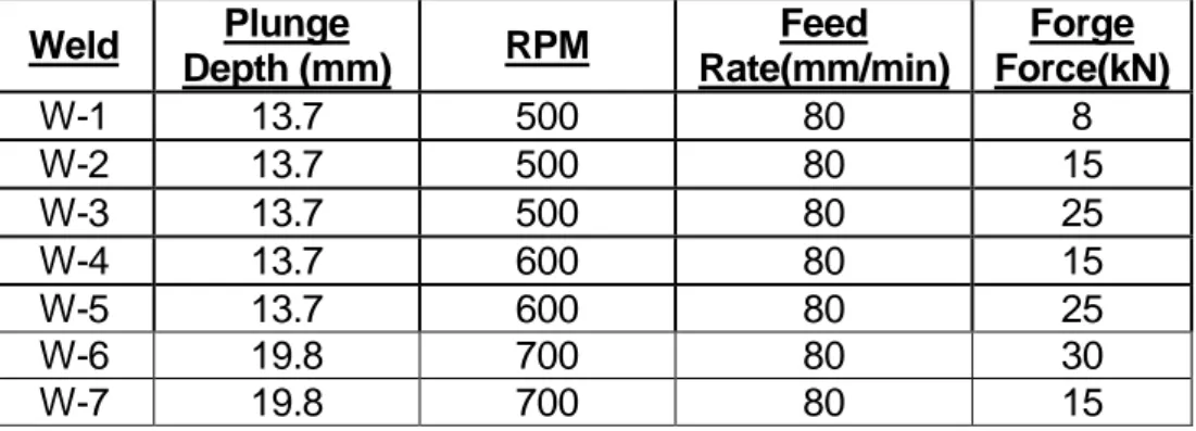
24 major alloying constituents, which makes it heat treatable. It is a medium strength alloy with excellent corrosion resistance. In plate form, 6082 is the most commonly used alloy and it also has the highest strength of any alloy in the 6000 series. This strength means that AA-6082 has replaced the older AA6061 in many applications such as; trusses, bridges, cranes and ore skips [15]. AA6082 was developed in Europe and AA6061 in the USA. AA6082 is generally selected for strength but is notch sensitive therefore when designing for fatigue life, AA6061 is generally selected. The thickness of the plate selected for the research was 25mm as the processing tool was to be designed to perform welds on plates up to this thickness. Plate sizes of 350mm x 120mm x 25mm were used for bead on plate welds and two plates of 400mm x 175mm x 25mm each were used for butt welds, as this would allow for the required samples to be prepared for tensile testing, hardness testing and macro-sections from selected welds. Another reason for the selection of the plate size was the size of the SSFSW mechanism and space needed for clamping. A parent plate sample was tested on a spectrometer and the results of the chemical composition are shown in Table 1, the typical mechanical properties are shown in Table 2 and the typical physical properties in Table 3.
Element Si Fe Cu Mn Mg Zn Ti Cr Al
Tested
% WT 0.99 0.292 0.056 0.6 0.68 <0.001 0.021 0.063 Balance
Standard
% WT 0.7-1.3 0.5max 0.1 max 0.4-1.0 0.6-1.2 0.2 max 0.1 max 0.25 max Balance
Table 1: Tested VS Standard Chemical Composition
Ultimate Tensile Strength 320 MPa
Vickers Hardness 100 HV
Chapter 3 Development of the SSFSW Tool
25
Density 2.70 g/cm3
Melting Point 555˚ C
Modulus of Elasticity 70 GPa
Thermal Conductivity 180 W/m.K
Thermal Expansion 24 x10-6 / k
Table 3: Typical Physical Properties [15]
3.3) MTS I-Stir PDS Platform
All weld trials were performed on the MTS I-Stir PDS platform, which recorded the process forces in X, Y and Z directions as well as spindle torque at a sample rate of 20Hz. The spindle and motion axes are all hydraulically actuated.
Figure: 3-1 - The MTS I-Stir PDS FSW Platform
3.4) Conventional Friction Stir Welding
To perform conventional friction stir welds on thick section plate, a tool and experimental setup was developed. The tool comprised a probe and separate shoulder which housed the probe as shown in Figure: 3-2. The probe was secured in the tool holder with a M10 set screw. This design was preferred as if the probe failed during welding, it would be easier and more cost effective to replace. The probe was;
26 truncated with a taper angle of 10˚, had three equi-spaced flats, neutral thread with a pitch of 1mm, a major diameter of 16mm tapering down to 10.74mm at the minor diameter and was 24.4mm in length to weld a 25mm thick plate. The probe was made from MP159 which was machined in the cold worked condition and then heat treated (aged) at 700°C for 4 hours. The probe was then left in ambient conditions to cool to room temperature. The tool holder and shoulder formed one component with the shoulder having a 30mm outer diameter, a 6˚ concave taper and being machined from H13 (W302) tool steel hardened to 52HRc. Working drawings of the probe and shoulder are shown in Appendix A.
Figure: 3-2 - Conventional FSW Tool with probe as insert
3.5) Experimental Setup
3.5.1) Axis Orientations
For interpretation and analysis purposes the following Cartesian system was used. The X direction was in the direction of welding, the Y direction was perpendicular to the welding direction and the Z direction was normal to these planes as illustrated in Figure: 3-3.
Chapter 3 Development of the SSFSW Tool
27 3.5.2) Conventional FSW Clamping Mechanism and Backing Plate
The plates were secured on the longitudinal sides using square bar as well as on top at each corner as shown in Figure: 3-3. The angles of the clamps were adjustable so, as to get optimum positioning to allow for clearance between the clamps and the FSW tool. A stainless steel backing plate was used underneath the plates to be welded which supported the plates and prevented the possibility of them being welded to the bed of the FSW platform. The choice of material of the backing plate was significant as its thermal conductivity influenced the heat during the welding cycle. A material with a higher thermal conductivity would absorb more heat from the weld than one with a lower thermal conductivity.
Figure: 3-3 - Clamping Mechanism and Backing Plate
3.6) Conventional Friction Stir Welds
Once the FSW tool design and experimental setup was finalised, bead on plate welds were performed. This was done to determine typical process response values and the influence of the change in weld traverse rate on these process response values. Data collected from these weld trials were used to determine initial starting parameters
Backing Plate
Downward Clamp Side Clamp
28 expected for the friction stir butt welding of 25mm thick AA6082-T6 plates. These welds were not sectioned for macroscopic evaluation as the purpose of these welds was to determine typical process parameters such as spindle speed and tool traverse rate as well as their effect on process forces and torques.
3.6.1) Bead on Plate Welds
The first bead on plate weld was performed under position control with process parameters used being; a spindle rotational speed of 400RPM; a weld traverse of 100mm/min with a ramp-up over 20mm from plunge position; a 2° tool tilt angle; a weld length of 120mm and a pin length of 24.4mm with the tool shoulder plunging 0.5mm into the plate. Figure: 3-4 shows the force and torque responses from the weld trial. The average forces were 28.12kN forge; a resultant X-Y force of 10.4kN at full traverse speed, a peak torque of 212.99N.m and an average welding stabilised torque of 143.9N.m. It was found that the pin length was too long, as sticking occurred when removing the plate from the backing plate. To resolve this problem, the tool pin length was reduced to 24.25mm and a second bead on plate weld trial was performed.
Figure: 3-4 – Bead on Plate FSW 1 Force and Torque Response 0 50 100 150 200 250 0 5 10 15 20 25 30 35 0 20 40 60 80 100 120 To rq u e (N .m ) Fo rc e (k N ) Weld Distance (mm)
Force and Torque Plot
Chapter 3 Development of the SSFSW Tool
29 The second bead on plate weld was performed using the position control method, by keeping the spindle rotational speed of 400RPM ,the tool tilt angle of 2° and the tool shoulder plunge depth of 0.5mm but increasing the weld traverse speed to 150mm/min with a 30mm ramp-up from plunge position to reduce heat input to the weld. The plot in Figure: 3-5 showed that this change in weld traverse speed and ramp-up distance caused the average X-Y resultant force to decrease to 9.9kN and the average forge force to increase to 29.46kN at full traverse speed with the peak torque being 231.57N.m and the average welding torque being 163.8N.m. The change in weld traverse speed did not have a significant effect on the X-Y resultant weld force. The forge force required to maintain the tool position as well as the process torque was however increased. This indicated that at higher traverse rates the tool is required to stir colder material than when welding at lower traverse rates as expected.
Figure: 3-5 – Bead on Plate FSW 2 Force and Torque Response
The typical process forces and torques obtained from the bead on plate welds were then used to determine starting parameters such as; spindle speed, feed rate and forge force for the creation of a 25mm thick AA6082-T6 butt weld. Once this had been
0 50 100 150 200 250 0 5 10 15 20 25 30 35 0 20 40 60 80 100 120 To rq u e (N .m ) Fo rc e (k N ) Weld Distance (mm)
Force and Torque Plot
30 done, two butt welds were performed and these welds were sectioned for macro-section evaluation and tensile specimens were prepared for tensile testing.
3.6.2) Butt Welds
The first butt weld 1 (BW1) was performed under position control to determine the typical forge force required to consolidate the weld and maintain contact between the tool shoulder and plate. The tool shoulder plunge was reduced to 0.1mm into the plates in an attempt to reduce flash formation and plate thinning. Process parameters of 350RPM and 150mm/min with a ramp-up over 30mm were used. This was done to produce a joint with a lower heat input as the size of the HAZ increases with increased heat input. As tensile samples usually fail in the HAZ, a smaller HAZ would lead to improved static tensile properties [2,3]. A tool tilt angle of 2° was selected as this angle was sufficient to maintain contact between the front of the shoulder and the plate with relation to the shoulder plunge of 0.1mm. A plunge rate of 15mm/min was selected. The weld length was set for 280mm. There was an increase in flash towards the end of the weld as can be seen in Figure: 3-6. This is believed to be due to an increase in temperature of the weld zone towards the end of the weld due to heat build-up. Due to the end of the weld being close to the edge of the plate, the heat cannot dissipate away from the weld zone as a result of the reduction in volume of material available for heat flow. This can also be seen by the decrease in the forge force as required to maintain the position of the tool.
Chapter 3 Development of the SSFSW Tool
31 There were no voids or wormhole defects visible in the macro-section as shown in Figure: 3-7. A distinct flow pattern was however visible from the advancing side to the retreating side which corresponded to the machined thread on the tool probe. This pattern became more evident away from the top surface of the weld indicating that at the top surface of the weld, the flow of material was governed by both the shoulder and the probe with the probe playing a more prominent role in the flow of material further away from the shoulder. In addition, in thick section FSW, the plasticised material was stirred around the probe in stacked layers from the advancing side to the retreating side with the thickness of layers dependant on the tool thread pitch. Figure: 3-8 shows the process forces and torques. The average forces recorded were: Forge force 33.5kN; X-Y resultant force 9.81kN at full traverse speed. The peak torque recorded was 288.18N.m and the average welding torque was 194.84N.m as seen in Figure: 3-8. The average forge force and process torque recorded was higher than those recorded for the bead on plate welds as expected as the parameters selected for BW1 was chosen to yield a lower heat input. There was no significant change in the average X-Y resultant force when comparing to the bead on plate welds.
32
Figure: 3-8 - Conventional FSW Butt Weld 1 Force and Torque Responses
Weld parameters similar to BW1 were then repeated for the second butt weld (BW2) the weld was however performed in force control at a set forge force of 35kN as the maximum forge force recorded during BW1 was 36.66kN. The weld had a good surface appearance but had excessive side flash on the retreating side as can be seen in Figure: 3-9. When the control mode changed from position control to force control (30mm into the weld), the tool plunged deeper into the material. This indicated that the set forge force of the weld was too high. This resulted in the formation of the excessive flash due to the material being too soft for the applied forge force plunging the tool deeper into the plates. This can be verified when analysing the forge position feedback shown in Figure: 3-10 .The flash formation gives an indication of the plate thinning as an increased shoulder plunge depth leads to an increase in flash which can be seen when analysing the weld surface with the plunge depth data. The process forces and torques are shown in Figure: 3-11.The average X-Y resultant force was 9.2kN at full traverse speed. The average weld torque was 195.37N.m and the peak torque was 311.12N.m. The macro-section of the weld is shown in Figure: 3-12 and no visible
0 50 100 150 200 250 300 350 0 5 10 15 20 25 30 35 40 0 50 100 150 200 250 300 To rq u e (N .m ) Fo rc e (k N ) Weld Distance[mm]
Force and Torque Plot
Chapter 3 Development of the SSFSW Tool
33 defects are present. The material flow pattern around the probe was however still visible.
Figure: 3-9 - Conventional Butt Weld 2 Surface
Figure: 3-10 - Conventional FSW Butt Weld 2 Shoulder Position Feedback
Figure: 3-11 – Conventional FSW Butt Weld 2 Force and Torque Responses -0.5 -0.4 -0.3 -0.2 -0.1 0 0.1 0.2 0.3 0.4 0.5 0 50 100 150 200 250 300 350 M axi m u m Sh o u ld e r Pl u n ge ( m m ) Weld Distance (mm)
Maximum Shoulder Plunge Depth
0 50 100 150 200 250 300 350 0 5 10 15 20 25 30 35 40 0 50 100 150 200 250 300 350 To rq u e (N .m ) Fo rc e [kN ] Weld Distance[mm]
Force and Torque Plot
34
AS RS
Figure: 3-12 - Conventional Butt Weld 2 Macro
3.7) Static Strength Testing
Once the conventional butt welds were performed, three tensile specimens were prepared per butt weld to evaluate the static strength of the welds; the results in Figure: 3-13 shows that the static tensile strength of the welds was consistent throughout the weld. The first weld (BW 1) showed an average static tensile strength of 216MPa compared to the second weld (BW 2) which had a 6.3% average higher ultimate tensile strength of 231MPa. Figure: 3-13 shows the fracture stress for each weld. The joint efficiency of BW 1 was 67.7% and that of BW 2 was 72.2%. The joint efficiency was calculated by comparing the UTS of the parent plate (320MPa, Table 2 pg24) to that of the welded joint.
Figure: 3-13 - Tensile Testing Results 200 205 210 215 220 225 230 235 1 2 3 UT S (M Pa) Sample
Static Test Results
BW1 BW2
Chapter 3 Development of the SSFSW Tool
35 When analysing fracture locations, as shown in Figure: 3-14, it was noted that all the samples from BW 1 fractured in the weld nugget. This suggested a possible lack of consolidation of the weld nugget, but as there was no major difference in the forge force during the two welds the failure in the nugget zone of BW1 samples was most probably due to the presence of oxides and not due to a lack of consolidation. All the samples from BW2 failing in the HAZ on the advancing side as expected as this is the general fracture location for friction stir welds.
Figure: 3-14 - Fracture Locations
The typical process responses associated with friction stir butt welds of thick section AA6082-T6 plate collected was then used to account for possible forces and torques applied to the tool during the welding process. These were then utilised in the design of a friction stir welding head unit with the ability to weld with a non-rotating tool shoulder.
BW1 -350RPM, 150mm/min, Position control
BW2- 350 RPM, 150mm/min, 35kN Forge Force
36
3.8) Sliding Shoulder Friction Stir Welding Head Unit
A number of considerations were taken into account while designing the new mechanism. The new head unit mechanism would need to be integrated into the existing I-Stir process development system (PDS) and allow for friction stir welding with a non-rotating tool shoulder. The total length of the unit needed to be kept to a minimum as space was limited on the I-Stir PDS. When looking at the structural integrity of the mechanism, the data collected from the conventional friction stir welds as well as the maximum forces that the I-Stir PDS could exert were taken into account and bearings were selected appropriately. The tool probe and shoulder needed the ability to move independently of each other and rotation of the shoulder needed to be prevented; the bearings needed to be cooled as it was expected that the process would generate a significant amount of heat. These bearings also had to withstand forces exerted during the welding process; bearing houses were required as well as bracing to support the head unit and prevent any deflection.
Figure: 3-15 - The SSFSW Head Unit Mechanism Schematic
(1)Rotating Shaft (2)Bearing Case (3)Cooling Flange (4)Support Bracing (5)Spacer (6)Shoulder Holder (7)Sliding Shoulder (8)Draw Bar (9)Tool Probe
Chapter 3 Development of the SSFSW Tool
37 A schematic of the mechanism is shown in Figure: 3-15 and was designed to integrate into existing equipment as well as the dimensions of the selected bearings. The cylindrical roller thrust bearings selected had a basic dynamic load rating of 80kN to account for the axial forging forces involved in the process. A drawncup needle bearing with a dynamic load capacity of 31.9kN was selected to transfer any side thrust loading generated to the bracing and away from the main shaft. Design considerations for the rotating shaft(1) required it to be mounted onto the spindle of the I-Stir PDS and accommodate the thrust and needle roller bearings selected for the design. This component made up the core of the mechanism. The material selected for the shaft was 316 stainless steel. As the cooling medium used was water, this would prevent the shaft from corroding and contaminating the cooling system of the I-stir PDS. The bearing case(2) was designed to house the thrust bearings which were subjected to the axial reaction force of that applied by the tool shoulder. This component did not rotate with the shaft and was machined from EN8 bar and zinc plated to prevent corrosion and to create an aesthetic effect. The cooling flange(3) was designed with respect to cooling capacity requirements and dimensions of the the bearing case and did not rotate with the shaft. This was the component which cools the shaft and prevented the bearings from overheating. It was machined from 316 stainless steel bar to prevent corrosion. A stainless steel 316 spacer(5) adjacent to the cooling flange was used to support the seal with the thickness of this component governed by the bolt sizes. The shoulder holder(6) was designed to house the sliding shoulder inserts and was designed to match the dimensions of the cooling flange, this component was zinc plated to prevent corrosion and for aesthetic purposes. A support bracing(4) was manufactured from aluminium 6082-T6 due to weight considerations. It was designed to prevent any deflection of the assembly caused by weld traverse forces and to prevent the bearing case, cooling flange, spacer and shoulder holder
38 from rotating with the shaft. The sliding shoulder(7) was the component in contact with the weld material and therefore therefore needed to withstand welding temperatures and to have a smooth surface finish. The shoulder had a flat profile and was 50mm in diameter. The draw bar(8) allowed for the tool probe(9) to be retracted at the end of the weld to prevent weld flash solidifying between the tool probe and shoulder. The length of this component was designed to conform to the stroke of the retractable shaft of the MTS PDS platform and the total length of the head unit mechanism . The unit is shown in Figure: 3-16 in the operating condition. Working drawings of all components can be seen in Appendix A.
Chapter 3 Development of the SSFSW Tool
39
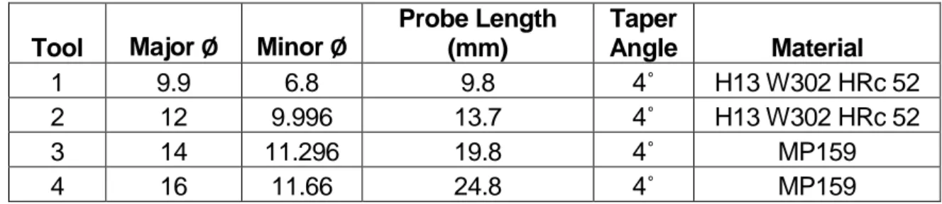
3.9) Tool Probe Designs
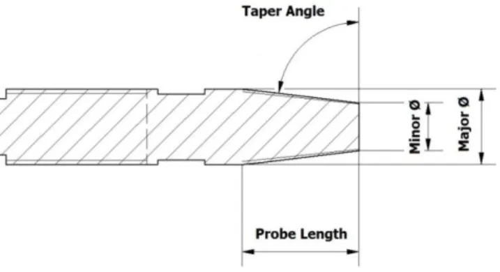
Current literature reports tool probe profiles with features such as flats or flute, induce a greater stirring action and generate more heat than featureless tool profiles. This is due to the increased contact area. For the SSFSW process, this was necessary as the probe needed to generate all the heat required to plasticise the material and create the metallurgical bond. A tapered tool with flats was selected as the preferred tool profile. This was chosen as a tool with flats could operate at higher process forces than tools with flutes due to their greater cross sectional area. Various sized tool probes were designed with dimensions as shown in Table 4. This was done to get an idea of the forces exerted on the probe and head unit during the process when welding at different weld depths by starting with the small probe and progressing to the bigger probes. All the probes had similar features as shown in Figure: 3-17. For example each had; a 4˚ taper angle, neutral thread of 1mm pitch, three equally spaced flats. The tools were fastened to the draw bar via thread. Tools 1 and 2 were made from H13 W302 tool steel hardened to 52HRc. The literature showed that this was the general tool material used for tools used for the friction stir welding of plate thinner than 16mm. Tools 3 and 4 were made from MP 159, a Ni-Co alloy and were age hardened at 700˚C for 4 hours to improve the UTS. This Ni-Co alloy is the general tool material currently used for the FSW of plate thicker than 16mm.
Table 4: Tool Pin Dimension
Tool Major Ø Minor Ø
Probe Length (mm) Taper Angle Material 1 9.9 6.8 9.8 4˚ H13 W302 HRc 52 2 12 9.996 13.7 4˚ H13 W302 HRc 52 3 14 11.296 19.8 4˚ MP159 4 16 11.66 24.8 4˚ MP159
40
Figure: 3-17 - Tool Probe Schematic
3.10) Tool Shoulder Design
One of the main problems with the SSFSW process is that plasticised material gets forced up between the tool probe and shoulder which solidifies when it cools. To help reduce the amount of plasticised material forced between the probe and shoulder, the clearance between these two parts becomes very important. If the clearance is too small the tool probe and shoulder can seize. If the clearance is too large, plasticised material gets forced up through the gap and the loss of this material can cause surface defects. Tool Shoulder inserts were made for each tool probe design, all of which were 50mm in major diameter with the internal diameter relative to the probe diameter. Tool shoulders were made from H13 (W302) tool steel hardened to 52 HRc. The shoulder inserts were ground to have a flat profile and a smooth surface appearance. Tool shoulder inner diameter and tool probe major diameter dimensions are shown in Table 5.
Tool Tool Major Ø Shoulder Internal Ø Clearance (mm)
1 9.9 10 0.05
2 11.7 11.9 0.1
3 13.9 14.4 0.125
4 16 16.3 0.15
![Table 3: Typical Physical Properties [15]](https://thumb-us.123doks.com/thumbv2/123dok_us/10941439.2982776/38.892.278.724.107.264/table-typical-physical-properties.webp)