Worcester Polytechnic Institute
Digital WPI
Major Qualifying Projects (All Years) Major Qualifying Projects
May 2014
Collaboratively Navigating Autonomous Systems
Edward Matthew MurphyWorcester Polytechnic Institute
Kevin S. Janesch
Worcester Polytechnic Institute
Madeline R. Burris
Worcester Polytechnic Institute
Quinn Perry
Worcester Polytechnic Institute
Ryan Patrick Fawthrop
Worcester Polytechnic Institute
Follow this and additional works at:https://digitalcommons.wpi.edu/mqp-all
This Unrestricted is brought to you for free and open access by the Major Qualifying Projects at Digital WPI. It has been accepted for inclusion in Major Qualifying Projects (All Years) by an authorized administrator of Digital WPI. For more information, please [email protected]. Repository Citation
Murphy, E. M., Janesch, K. S., Burris, M. R., Perry, Q., & Fawthrop, R. P. (2014).Collaboratively Navigating Autonomous Systems. Retrieved fromhttps://digitalcommons.wpi.edu/mqp-all/2621
Collaboratively Navigating
Autonomous Systems
A Major Qualifying Project Report Submitted to the Faculty of the WORCESTER POLYTECHNIC INSTITUTE
In partial fulfillment of the requirements for the Degree of Bachelor of Science
By ___________________________________ Madeline Burris ___________________________________ Ryan Fawthrop ___________________________________ Kevin Janesch ___________________________________ Edward Murphy ___________________________________ Quinn Perry
Project Number: AW1 CNAS Date: 05/01/2014
Sponsoring Organization:
The MathWorks
Project Advisors:
___________________________________ Professor Alexander M. Wyglinski ___________________________________ Professor Taskin Padir
Abstract
The objective of this project is to focus on technologies for enabling heterogeneous networks of autonomous vehicles to cooperate together on a specific task. The prototyped test bed consists of a retrofitted electric golf cart and a quadrotor designed to perform distributed information gathering to guide decision making across the entire test bed. The system prototype demonstrates several aspects of this technology and lays the groundwork for future projects in this area.
Acknowledgements
Professor Alexander M. Wyglinski, Ph.D. Professor Taskin Padir, Ph.D.
MathWorks Bob Boisse
Elizabeth Tomaszewski and WPI Facilities WPI Robotics Learning Center
Tracey Coetzee Cathy Emmerton Joe St. Germain Marleny Ortiz
Executive Summary
Communication between autonomous vehicles is becoming increasingly relevant as the number of robots in operation increases. The goal of this project is to create a platform system of autonomous robots, pooling information about their environment and using it as the basis for navigation decisions. This system will serve as a test platform to explore the benefits of collaborative decision-making across the distributed robotic agents. There are three main problems that this project will address:
1. Establishing communication between the distributed agents that make up the system
2. Contribution of sensory information from each distributed agent as to create a map of the environment.
3. Using the environmental map to make the best navigation decisions.
In order to create this test platform system, the team pinpointed three main objectives that must be met.
• The first objective consists of creating a physical ground vehicle capable of taking commands from a control system, and turning them into physical actions.
• The second objective is to create a collection of software that is capable of pooling environmental data, processing it, and providing navigation commands to the rest of the system.
• The third objective is to create an aerial platform that will send supplemental environmental information back the decision making engine.
In order to create this autonomous system, an electric golf cart will be used for the unmanned ground vehicle (UGV), and AR Parrot Drones will be used for the unmanned aerial vehicles (UAV). The ground vehicle will navigate by performing visual simultaneous localization and mapping (SLAM), using forward-facing stereo cameras to map the environment. The UAVs will have onboard cameras, collecting images of the environment and sending them back to the UGV. The UAVs will also send their positional data back to the ground vehicle. Once the images and positional information are received on the UGV, blob detection is applied so that obstacles, and their locations, can be identified. These obstacles are then added to the global map of the environment.
The electric golf cart had to be retrofitted as to incorporate drive-by-wire control of its functions. Linear actuators were used to control the steering and the braking of the golf cart. With feedback positioning, the computer knows how far the actuator arms are extended at all times. Since the throttle of the golf cart is controlled by a continuously variable potentiometer that is adjusted by the accelerator pedal, the team chose to use a digital potentiometer to emulate it.
The UGV, UAV, and computing systems are designed to be modular so that the individual aspects of the project can be improved separately, replaced, or upgraded as needed without requiring restructuring of the entire system.
This autonomous system uses a variety of software that utilizes MATLAB and ROS. An open source software package called ROS-MATLAB Bridge was used to allow MATLAB to take advantage of the publisher subscriber communication system that ROS creates. MATLAB was used for blob detection and control of the system. ROS was used to provide a standard
Open source software packages were used to try to move the project along, but due to a lack of documentation and conflicts between software the implementation of these open source packages proved difficult. By the projects conclusion, SLAM was implemented and worked with a Microsoft Kinect, but not the original Raspberry Pi cameras. The golf cart was controlled through MATLAB, and the cameras were able to detect orange blobs.
Table of Contents
Abstract ... i
Acknowledgements ... ii
Executive Summary ... iii
Table of Contents ... vi
List of Figures ... ix
List of Tables ... xiii
List of Acronyms ... xiv
1. Introduction ... 1
1.1 Motivation ... 1
1.2 Formation and Coordination of Autonomous Agents ... 3
1.3 Technical Challenges ... 6
1.4 Project Objectives ... 7
1.5 Report Structure ... 10
2 Current State of the Art ... 11
2.1 The DARPA Grand Challenge ... 11
2.2 Current Autonomous Vehicles ... 12
2.3 Chapter Summary ... 18
3 Principles of Autonomous Vehicles ... 19
3.1 External Sensing ... 20
3.2 Internal Sensing ... 31
3.3 Data Fusion and Path Planning ... 33
3.3.1 Simultaneous Localization and Mapping ... 33
3.3.2 Kalman Filters ... 35
3.3.3 Path Planning ... 37
3.4 Ground Vehicle Mechanics ... 39
3.4.1 Steering ... 39
3.4.2 Braking ... 42
3.4.3 Actuation ... 43
3.5 Aerial Platforms ... 45
3.5.1 Aerial Vehicle Motion ... 47
4 Proposed Implementation ... 51
4.1 Design Specifications ... 53
4.1.1 Experiment Specifications ... 53
4.1.2 Information and Sensor Connectivity ... 54
4.1.3 Power Management Constraints ... 56
4.2 Proposed Design ... 57
4.2.1 Aerial Platform ... 57
4.2.2 Ground Platform ... 58
4.2.3 Decision Making and Control Logic ... 60
4.3 Project Logistics ... 62 4.3.1 Financial Considerations ... 64 4.3.2 Time Considerations ... 65 4.3.3 Workspace ... 66 4.3.4 Safety ... 67 4.4 Chapter Summary ... 69
5 Ground Vehicle Hardware ... 70
5.1 Steering ... 70
5.1.1 Actuator Selection ... 71
5.1.2 Steering Mount Prototypes ... 74
5.1.3 Final Connection Design ... 77
5.2 Braking ... 80
5.3 Throttle ... 83
5.3.1 Throttle Control Testing ... 84
5.3.2 Throttle Switch ... 85
5.4 Safety ... 87
5.5 Chapter Summary ... 90
6 Ground Vehicle Software ... 91
6.1 Vehicle Control ... 91
6.2 Inertial Navigation ... 93
6.3 Stereo Vision and SLAM ... 95
6.4 Path Planning ... 104
6.6 Chapter Summary ... 106
7 Aerial Implementation ... 108
7.1 Drone Communication with ROS ... 108
7.2 Aerial Navigation ... 111
7.3 Cone Identification ... 121
7.4 Experimental Results ... 124
7.5 Chapter summary ... 125
8 Conclusions and Future Work ... 126
8.1 Future Work ... 127
9 Bibliography ... 131
Appendix A: Purchase List ... 135
Appendix B: MATLAB Classes for ROS-MATLAB Bridge ... 138
Appendix C: Drone Launch File ... 145
Appendix D: Python Drone Controller ... 147
Appendix E: Python Drone Navigation Data Extraction ... 150
Appendix F: Python Drone Flight Controller ... 151
Appendix G: MATLAB Drone Navigation ... 154
List of Figures
Figure 1.1: An illustration of Moore's Law showing how the number of transistors per die
increase at a steady logarithmic pace over time [2]. ... 2
Figure 1.2 : Diagram depicting the communication systems proposed by the DOT RITA. This is the layout that RITA plans to use to start in the standardization of autonomous vehicles across manufactures [6]. ... 4
Figure 1.3: California PATH platooning demonstration in San Diego in 1997. There are 8 Buick LeSabres driving in a platoon, each utilizing V2V communications [8]. ... 6
Figure 1.4: A diagram of the team's proposed system design. ... 9
Figure 2.2: The Oshkosh TerraMax Vehicle. This vehicle was designed to navigate extreme terrain, and comes equipped with a Velodyne HDL-64e Lidar module. The TerraMax also has wheels that can automatically change tire pressure to best suit its driving environment. This vehicle is capable of autonomous convoy driving [10]. ... 13
Figure 2.3: The 3D map of what the onboard computer of the Google Car sees. This is a combination of sensory information from its Lidar data overlaid on an in-depth map of the area [12]. ... 14
Figure 2.4: The Google Car equipped with the Velodyne HDL-64e Lidar Module [13]. ... 15
Figure 2.5: RQ-2A Pioneer Unmanned Aerial Vehicle ... 16
Figure 2.6: General Atomics MQ-1 Predator Drone ... 17
Figure 2.7: Amazon looks to use quadcopter drones to deliver packages in the near future. ... 17
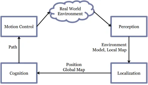
Figure 3.1: This is a concept diagram for a generic independent autonomous agent. This diagram assumes that all of the agent's data collection and processing is done onboard, and that the agent does not collaborate with other autonomous agents. ... 19
Figure 3.3: This speckle pattern is an example from one of PrimeSense’s patent applications [29] for 3D mapping using structured light. This pattern would be repeated when broadcast on a surface. Annotation 92 denotes a light-refracting bump. ... 27
Figure 3.4: Velodyne HDL-64E Lidar module, with cover (left) [35] and without (right) [36]. The top cylinder includes the laser emitters and receivers, and rotates at up to 900 rpm to acquire fifteen full 360 degree, 86,000-point scans per second. ... 29
Figure 3.5: Diagram of the radar systems in place in the Mercedes-Benz Intelligent Drive platform [37]. The orange swaths in the image indicate the areas covered by different radar modules. ... 30
Figure 3.6: Flow chart of how a SLAM algorithm can work. ... 34
Figure 3.8: Shows the new covariance (in green) after a measurement update. Illustrates that the confidence in the new estimate is greater than that of the prediction or the noisy measurement [39]. ... 36
Figure 3.9: A simple example of how A* works. This shows that A* can be get complicated when the space to search becomes very large [42]. ... 38
Figure 3.10: Ackerman Steering Instant Center of Rotation ... 40
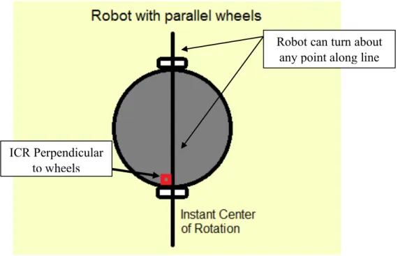
Figure 3.11: Robot with parallel wheels and infinite Instant Centers of Rotation ... 41
Figure 3.12: Schematic of drum braking systems. The brake show is pushed outward, applying pressure to the interior wall of the brake drum, slowing the spinning of the drum [39]. ... 42
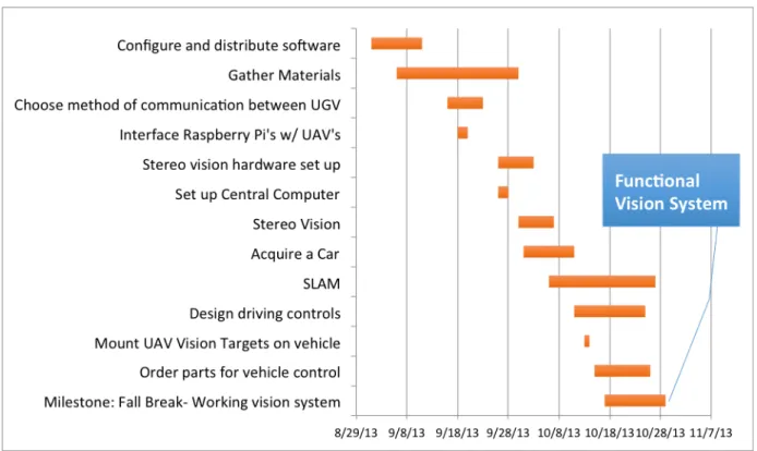
Figure 3.13: For disk brake systems, the calipers squeeze the brake pads onto the revolving disk, slowing the disk to a stop [39]. ... 43 Figure 3.14: Rack and pinion mechanical linear actuator. This actuator coverts the rotational motion enacted on the steering wheel into linear motion along the steering rack [42]. ... 44 Figure 3.15: The internal componenets of an electromechanical linear actuator. The rotational motion of the motor turns a gear, which rotates a screw. The action of the screw forcing itself through a fixed nut results in the linear motion of the actuator arm [43]. ... 45 Figure 3.16: The Asctec Hummingbird quadcopter ... 45 Figure 3.17: The Arducopter as built by a hobbyist . The body of this quadcopter was sold
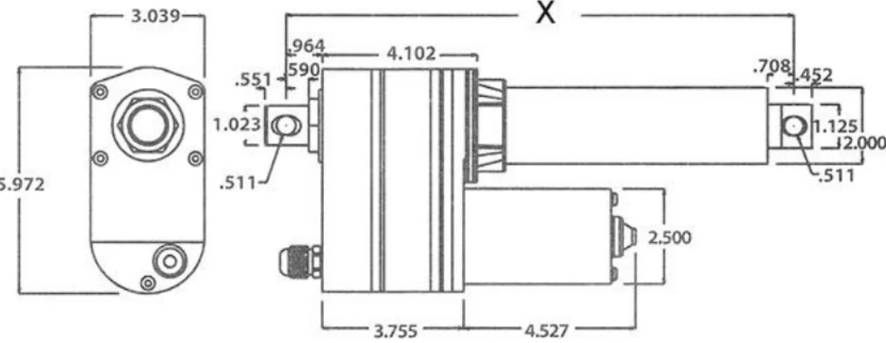
separately at the time of quadcopter selection. ... 46 Figure 3.18: The AR Parrot Drone 2.0 with the indoor shell equipped. ... 47 Figure 3.19: Six degrees of freedom in relation to aerial vehicles. This figure represents x as forward and back, y as right and left, and z as up and down. ... 47 Figure 3.20: Quadrotor torque generation and resulting motion. ... 48 Figure 4.1: The process a robot follows when navigating in an unknown environment. ... 51 Figure 4.2: Final cart, with electro-mechanical and safety systems installed. The drive-by-wire and computer controlled steering systems are used for motion control, and the cameras and sensors get mounted on the front to realize the real world environment. ... 52 Figure 4.4: Proposed project timeline for the first quarter of the project. ... 63 Figure 4.5: The proposed project timeline for the second quarter of this project. ... 63 Figure 4.6: Proposed project timeline for the final two quarters of this project. The final quarter was designated specifically for paper writing, and little to no technical work was to be done. ... 64 Figure 4.7: Photograph of one of the emergency stop switches installed in the vehicle. When the switch is activated, the powertrain of the vehicle is disabled, and the brakes are engaged to prevent injury. ... 68 Figure 5.1: View of the mounting point used to control the steering using the linear actuator. In connecting the linear actuator here, the original steering can remain installed. ... 71 Figure 5.2: Diagram of the large linear actuator the team intended to use for the steering (in inches). ... 71 Figure 5.3: The 560 lb linear actuator being held underneath the front bumper, with the actuator arm nearing the mounting point. The actuator barely fits and since there still would need to be a connection piece from the actuator to the steering rack, was deemed too large for use. ... 72 Figure 5.4: Diagram of the smaller actuator that was used to control the steering in the final revision (dimensions in inches). ... 73 Figure 5.6: Front view of the location that the linear actuator was mounted to. ... 75 Figure 5.10: A prototype revision of the steering mount and tie-rod. From left to right, the parts include the new female-threaded ball joint, the threaded stock connector, the inline ball joint, the stock that connects to the linear actuator, and the linear actuator. ... 77 Figure 5.11: The last prototype steering assembly installed. One more revision was made after this, in favor of more durable components, and less angles. ... 78 Figure 5.14: Actuator fully extended. The angle of the connection between the steering rack and the linear actuator has been reduced from the previous ... 80
Figure 5.15: The braking mechanism in place on the cart. This shows the device that actuates the cable, applying the brakes. ... 81 Figure 5.16: View of under the cart where the linear actuator is mounted for the braking. ... 82 Figure 5.17: Sabertooth Motor Controller circuit. The blue, yellow, and grey (representing white) potentiometer reference wires let the computer know the position of the actuator arms. For safety reasons, there is a closed emergency switch between the battery and the Sabertooth. ... 83 Figure 5.18: Wiring schematic of the golf cart without any modification from the group. This shows how the powertrain is connected to the battery system of the vehicle, and the location of the key switch in the wiring. ... 84 Figure 5.19: The throttle switch in "manual control" state. The original continuous
potentiometer is in place. ... 86 Figure 5.20: The throttle switch in the "digital control" state. The new connections to the digital potentiometer are in place, and the pins 2 and 3 are tied together on the motor controller. ... 87 Figure 5.21: Schematic of the existing electrical system in place on the golf cart. Highlighted are the key switch and the solenoid. The emergency switch system was implemented in series with the key switch, so that when the switches were depressed, the power would be cut to the cart’s drivetrain. ... 88 Figure 5.22: Emergency switch located at the front of the vehicle. ... 89 Figure 5.23: Emergency switch located in the footwell of the vehicle, for easy access to the driver. The button could be depressed by the driver's foot in emergency situations, allowing them to keep their hands safety within the vehicle. ... 89 Figure 5.24: Emergency switch at the rear of the vehicle. ... 90 Figure 6.1: Changes made to the compiler flags in
rosserial_arduino/src/ros_lib/ArduinoHardware.h to accommodate the MK20DX128 (Teensy 3.0) and MK20DX256 (Teensy 3.1). These changes were submitted as pull request 90 on
GitHub, and merged into the ros-drivers:hydro-devel branch of the project [50]. ... 91 Figure 6.2: Vehicle controller software organization and inputs/outputs. The calculated vehicle speed and throttle control loop were not implemented in this iteration of the project due to time constraints. ... 92 Figure 6.3: Pololu MinIMU-9 v2 IMU, with pinout and axes. The LSM303DLHC and L3GD20 are interfaced to the Teensy via I2C. ... 93 Figure 7.1: Data transfer from the drone to ROS, through ROS-MATLAB Bridge, to MATLAB and vice versa. ... 111 Figure 7.2: Drone at a standard hover position ... 112 Figure 7.3: Abnormally low hover height caused by reflection of ultrasonic pings and non-solid surfaces. ... 113 Figure 7.4: Low battery can cause significant drift and launch errors. ... 113 Figure 7.5: Drone rolled to right and flying uncontrollably. ... 114 Figure 7.6: The drone is using ar_pose to localize to the black screen of the computer seen in the lower left hand corner of the image. A pose is returned giving the drone’s position in relation to this screen. ... 117 Figure 7.7: A PD control loop uses the error of a system to determine the appropriate movements to reach a desired position. ... 119
Figure 7.8: Example code for the proportional derivative control loop utilized for waypoint navigation. ... 120 Figure 7.9: The drones are programmed to move via strafing. This means the drones will move diagonally to an end position and will always have the same heading. ... 121 Figure 7.10: The image data processed by the custom blob detection function displays only orange blobs currently within the view of the camera. ... 123
List of Tables
Table 3.1: Comparison of hobbyist-grade IMU modules to a commercial, automotive-grade module. Hobbyist-grade IMUs typically perform a power-on calibration, but noise and overall calibration need to be performed by the user. Often, noise cancels out additional precision from additional ADC bits. ... 21 Table 3.2: Comparison of different Lidar modules currently available. ... 28 Table 4.1: Specifications of different wireless standards. ... 55 Table 5.1: Table of different available actuator lengths. The 150 lb actuator with a stroke size of 4 inches is 9.51 inches in length when fully retracted, a whole 8 inches shorter than the 560 lb actuator. The actuator with a stroke size of 8 inches is 13.51 inches when fully retracted, 4 inches shorter than the 560 lb actuator [44]. ... 73 Table 7.1: Data available through the ardrone_autonomy package from the AR Drones as seen in the documentation. ... 109
List of Acronyms
Acronym Definition Context
AHRS Attitude and Heading Reference System Sensing
API Application Programming Interface Software programming
CAN Controller Area Network Device communications
CCD Charge-Coupled Device Sensor design
CMOS Complementary Metal-Oxide Semiconductor Sensor design
CNAS Collaboratively Navigating Autonomous Systems Project shorthand
CPU Central Processing Unit Computing, hardware
DARPA Defense Advanced Research Projects Agency Organization
DIY Do It Yourself Activity
DRC DARPA Robotics Challenge Event
EKF Extended Kalman Filter Computing, algorithm
FOV Field of View Sensor attribute
GPS Global Positioning System Sensing
GPU Graphics Processing Unit Computing, hardware
GUI Graphical User Interface Computing, software
I2C, I2C Inter-IC Communication Device communications
IC Integrated Circuit Computing, hardware
IEEE Institute of Electrical and Electronics Engineers Organization
IMU Inertial Measurement Unit Sensing
IPC Inter-Process Communication Software
IR Infra-red Device communications
JPEG Joint Photographic Experts Group File format
LAN Local Area Network Distributed systems
MATLAB Matrix Laboratory Software
MEMS Microelectromechanical Systems Sensing
MMAL Multi-Media Abstraction Layer Software
NATO North Atlantic Treaty Organization Organization
NDA Non-Disclosure Agreement Information
NMEA National Marine Electronics Association Organization
NTP Network Time Protocol Software
OS Operating System Software
PCL Point Cloud Library Software, library
PID Proportional Integral Derivative Computing, algorithm
PWM Pulse-Width Modulation Device communications
RAM Random Access Memory Computing, hardware
RLG Ring Laser Gyroscope Sensing
RPF Raspberry Pi Foundation Organization
ROS Robot Operating System Software, tool
SDK Software Development Kit Software, tool
SDR Software-Defined Radio Device communications
SLAM Simultaneous Localization and Mapping Software, algorithm
SLI™ Scalable Link Interface (Nvidia trademark) Device communications
SPI Serial Parallel Interface Device communications
SSD Solid-State Disk/Drive Computing, hardware
SVN Subversion Software, version control
UAV Unmanned Aerial Vehicle System
UGV Unmanned Ground Vehicle System
USB Universal Serial Bus Device communications
V2I Vehicle-to-Infrastructure System topography
V2V Vehicle-to-Vehicle System topography
VGA Video Graphics Array Computing, hardware
1.
Introduction
Robotics, unmanned systems, and automatic decision-making are becoming an integral component of the future of society. While the number of robots in daily operation increases, anywhere from manufacturing, on the roads, or in our homes, the need for robotic collaboration becomes increasingly apparent. As the industry gains popularity, research must be done on the methods and effectiveness of homogeneous collaboration among autonomous robotic systems.
1.1 Motivation
The current generation of robotics is based around higher-level computer decision-making. In conventional automation, the task to be performed would be completely predefined, every movement that the robot would make calculated through the programming code. As Bill Gates, Co-founder of Microsoft, stated in Scientific American, "One trend that has helped [robotics] is the increasing availability of tremendous amounts of [processing] power. One megahertz of processing power, which cost more than $7,000 in 1970, can now be purchased for just pennies" [1]. He goes on to explain how the costs of data storage and hardware have declined in a similar fashion. "As computing capacity continues to expand, robot designers will have the processing power they need to tackle issues of ever greater complexity" [1]. Due to the increase in the available amount of computing horsepower per dollar, more computationally expensive tasks have become achievable.
In 1965, Intel co-founder Gordon E. Moore made a prediction known as Moore’s Law. He predicted that the number of transistors on integrated circuits would double approximately every two years [2]. This means that the performance of these integrated circuits will double every two years with respect to processing speed and memory capacity. This prediction has been used as a target for the computer sector for decades, defining growth and research and
development effects within this industry [2]. In fact, this prediction has held true for approximately 50 years, although it is anticipated to slow in the near future as the semiconductor devices are reaching their physical limits.
Figure 1.1: An illustration of Moore's Law showing how the number of transistors per die increase at a steady logarithmic pace over time [2].
The constant increase of computer processing power has directly impacted the robotic sector providing new possibilities for robot integration into the daily life of society. One area that has been significantly impacted by computer processing technology are autonomous vehicles. Due to the miniscule cost of processing power, nearly every major car manufacturer has an option for assistive braking, lane drift prevention, obstacle recognition, or any combination of these types of semi-autonomous features. Nissan has plans to sell a self-driven car in the market by the year 2020 [3], and the company currently has a test vehicle that is road legal in Japan. It utilizes a semi-autonomous system called the ‘Advanced Driver Assist System’,
which enables the vehicle to stop at red lights, slow down for traffic congestion, and even take an exit on a highway [4].
1.2 Formation and Coordination of Autonomous Agents
Once electronic assist features, like Nissan’s ‘Advanced Driver Assist System’, become standard on the majority of automobiles on the road, the next step will be for the separate robotic systems to communicate data to one another, in order to better make decisions about the
environment. A pilot project by University of Michigan is testing vehicle-to-vehicle (V2V) communications devices that broadcast location and speed information to other vehicles while gathering the same data [5]. This allows the car to notify the driver of potential threats, paving the way for pre-emptive safety measures in automobiles [5]. For example, if a driver encounters an obstacle in the road and brakes, the car would indicate to the vehicles in its vicinity that it is drastically slowing down, and the other drivers could react based on this information.
In addition to V2V communications, vehicle-to-infrastructure (V2I) communications allow cars to receive information from the road itself, providing warnings of accidents, cars in blind spots, school zones, etc [5]. This combination of information from other vehicles and the actual road itself will prove to be very helpful to drivers, but also offer autonomous cars "an abundance of trustworthy, useful information" [5]. This adds a new dimension of decision-making possibilities for the systems to deal with, but also will allow a well-designed system to operate much more safely. So, in the event of a car applying emergency braking to avoid collision with an obstacle, other cars approaching that location would slow down and move out of the path of the hazard. This could mitigate much of the cause of traffic, uniformed drives acting in a reactive scenario, as opposed to making informed decisions and planning to avoid trouble before it is reached.
The US Department of Transportation (DOT) Research and Innovative Technology Administration (RITA) recognizes the importance of connected vehicle technology, and is in the process of researching and defining technology standards to be implemented on vehicles sold commercially. The DOT has defined several applications that the connected vehicle technology must address: safety applications, mobility applications, and environmental applications [6].
Figure 1.2 : Diagram depicting the communication systems proposed by the DOT RITA. This is the layout that RITA plans to use to start in the standardization of autonomous vehicles across manufactures [6].
According to the RITA, “connected vehicle safety applications are designed to increase situational awareness and reduce or eliminate crashes through vehicle-to-vehicle (V2V) and vehicle-to-infrastructure (V2I) data transmission that supports: driver advisories, driver warnings, and vehicle and/or infrastructure controls.” [6]. RITA also claims that these systems will have the ability to prevent up to 82 percent of accidents involving unimpaired drivers annually.
“Connected vehicle environmental applications both generate and capture environmentally relevant real-time transportation data and use this data to create actionable information” where this data is then used to make routing decisions that have the minimum environmental impact [6]. For example, this would prevent a traveler from driving into a traffic jam, but rather reroute them on the most efficient route around the congestion.
These technological advances in communication are essential steps towards the realization of a world of autonomous cars. A platooning project called SARTRE (Safe Road Trains for the Environment) has begun testing on roads in Europe using Volvo's specialized autonomous vehicles. Platooning is a system of linked vehicles that drive themselves based on their V2V connections to each other and the human-operated lead vehicle. The purpose of this platoon is to allow the human operator in each autonomous vehicle to be relived the task of driving, and to benefit the fuel economy of the vehicles by limiting the amount braking and acceleration seen in human operation [7].
The SARTRE Project is not the first of its kind, however. In 1997 California Partners for Advanced TecHnology (PATH) successfully demonstrated a platoon of 8 Buick LeSabres in San Diego, CA. By utilizing radar and radio V2V communication, the cars are able to coordinate maneuvers such as changing lanes, adjusting car spacing, accelerating and decelerating, and even changing positions in the platoon. California PATH reported that, “the platoon scenario at Demo ‘97 in San Diego did not include the full range of functions that would be needed for an operational automated highway system…” [8]. They set the groundwork for future platooning projects, and as technology advances, realizing these unmet goals become easier to realize.
Figure 1.3: California PATH platooning demonstration in San Diego in 1997. There are 8 Buick LeSabres driving in a platoon, each utilizing V2V communications [8].
1.3 Technical Challenges
The goal of this project is to create a platform made up of a system of autonomous robots, which utilize sensors to collect information about the environment and contribute that information to a central data pool. This pool of data is then used for making navigation decisions within the system. For the rest of this paper, the autonomous robots within the networked system will be referred to as distributed agents. This project will contribute a robotic system to serve as a test platform that enables distributed decision making across multiple homogeneous agents, ultimately allowing for testing of electronic security, electromagnetic security, and sensor security attacks on networked systems of distributed robotic agents.
• Challenge 1: Communication between agents. The most important aspect of this system is the communication between the distributed agents. This
The lead car of the platoon
communication is key to the transmission of sensor and location data from the distributed agents to the decision making engine. For systems like this one, it is important to explore requirements for the communication system, and design that system to be robust under maximum load.
• Challenge 2: Realizing the environment. Once communication is established between all of the distributed agents, the agents need to contribute their onboard sensor information to the system’s environmental map. This map is used to make decisions about the actions that the system takes.
• Challenge 3: Acting upon the environment. Using the environmental map created by the fusion of all the sensor information within the system, the autonomous system must make navigation decisions to safely reach a desired destination. The system must weigh all the possible options, and choose the one that is safest and most efficient.
1.4 Project Objectives
This project is broken up into three main project objectives:
• Objective 1: Cyber-physical System for Autonomous Ground Vehicle. This portion of the project consists of the creation of the physical ground vehicle. The vehicle must be capable of operation in the defined test environment, and be able to take commands from a control system, and turn those commands into physical action.
• Objective 2: Navigation, Path Planning, and Data Fusion. This portion is the brain of the project. This collection of software must be capable of collecting data about the operating environment, process that data, and ultimately provide
navigation commands to the rest of the system so that physical actions can be performed.
• Objective 3: Aerial Platform for Expanded Environmental Awareness. This is the portion of the project that makes it stand out from other modern autonomous systems. The ground vehicle sensor information will be supplemented by auxiliary data, sent back to the decision engine by forwardly deployed aerial agents. These agents are responsible for contributing information to the environmental map that would otherwise go unrealized by the ground vehicle. The end result of this project will be an autonomous system consisting of two distributed agents: one autonomous unmanned ground vehicle (UGV) and one autonomous unmanned air vehicles (UAV). This system will have the ability to navigate safely to a designated end position, while avoiding obstacles and detecting hazards. Data will be passed between the vehicles (UGV to UAVs and back) while performing the navigation and obstacle avoidance. This V2V communication between these two distributed agents demonstrates how the transmission of data is scalable, and that smarter and more efficient decisions can be made off of a more diverse pool of data. The distributed agents will be aware of their location in relation to the environment around them, while also tracking the locations of all the agents in the system. This design simulates the functionality of a system, which may be used, in the future, for an autonomous convoy. This will allow for a future project to use this unmanned autonomous system as a platform to begin testing the security and vulnerability concerns, which are associated with of these types systems.
Figure 1.4: A diagram of the team's proposed system design.
In order to accomplish the goal of making a collaboratively navigating autonomous system, the project will implement a means of communications between a ground vehicle and auxiliary unmanned aerial vehicles. The ground vehicle will be able to navigate an obstacle course independently of aerial vehicles. The UAVs will send information about the environment to the ground vehicle, which the ground vehicle will then use to generate a more accurate navigation solution to its end goal.
For proof of concept, a used golf cart will be used for the ground vehicle, and AR Parrot Drones will be used for the aerial vehicles. The ground vehicle will navigate by performing visual simultaneous localization and mapping (SLAM), using forwards facing stereo cameras to map the environment. There will also be ultrasonic range finders, used as a failsafe, to prevent
collisions. The UAVs will have onboard cameras, collecting images of the environment and sending them back to the UGV. The UAVs will also send positional data back to the ground vehicle so the location can be calculated. Once the images and positional information are received on the UGV, blob detection is applied so that obstacles, and their locations, can be identified. These obstacles are then added to the global map to the environment.
The deliverables that this project contributes to the field are:
● A test bed system that demonstrates the ability for multiple homogeneous autonomous robots to share sensor information.
● A decision making engine that acts upon the shared pool of sensor data to make decisions about navigation.
1.5 Report Structure
The structure of this report is as follows: Chapter 2 will provide a detailed overview of the fundamentals involved in the design and fabrication of an autonomous system of robotic agents. Chapter 3 describes the proposed system to be delivered at the end of the project duration. Chapter 4 will delve into the details of the design for the aerial agent component of the collaboratively navigating autonomous system, while Chapter 5 breaks down the specifics of the ground agent. Chapter 6 details the logistics of the ground vehicle control systems, and Chapter 7 discusses the theory and challenges of path planning for this type of system. Chapter 8 contains a discussion and analysis of the final system delivered at the end of the product, highlighting the project team’s challenges and their solutions. To wrap up this report, Chapter 9 concludes and discusses the futures uses of the deliverables contributed by the project team.
2
Current State of the Art
There is a great deal of research going into the creation and refining of autonomous ground vehicles in the world today. Much of this research is achieved through competitions that involve crowd sourcing from multiple teams. By pooling together such a wide range of talent, an accelerated progression has been made in many aspects autonomy.
2.1 The DARPA Grand Challenge
The Defense Advanced Research Projects Agency (DARPA) is a research organization of the United States Department of Defense. The DARPA Grand Challenge is a series of prize competitions that began in 2004 and focus on the development of autonomous robotics. DARPA awards the top teams of each competition with cash prizes, in hopes that they continue to develop their projects or compete in future challenges. By pooling together the work of thousands of talented engineers, great advances can be made in autonomous robotics while sparking the interest of more engineers.
The first DARPA Grand Challenge concentrated on traversing off-road terrain. Since no team was able to complete the course, the prize went unclaimed and many competed the following year in the next challenge. The DARPA Urban Challenge, held in 2007, was the third of DARPA’s Grand Challenges, but the first to feature autonomous ground vehicles in a mock city environment. “The DARPA Urban Challenge is an autonomous vehicle research and development program with the goal of developing technology that will keep warfighters off the battlefield and out of harm’s way” [9]. While the previous two challenges concentrated more on an off-road environment; the focus of the Urban Challenge was to obey traffic laws, detect and avoid other vehicles, and make intelligent decisions in real time.
The goals of the program are as follows:
• Accelerate autonomous ground vehicle technology development within the areas of
sensors, navigation, control algorithms, machine intelligence, and systems integration.
• Demonstrate an autonomous vehicle able to operate independently in a realistic urban
environment through a field of live traffic.
• Attract and energize a wide community of participants to bring fresh insights to the
problem of developing a truly robust autonomous vehicle and provide qualified performers to develop autonomous ground vehicles [for the Department of Defense].
2.2 Current Autonomous Vehicles
One vehicle, the TerraMax built by the Oshkosh Truck Corporation competed in the first two DARPA Grand Challenges and has been developed further alongside the United Department of Defense, despite its failure to win either of the competitions. The result is the Oshkosh Defense TerraMax UGV, which is a “vehicle kit system that advances perception, localization, and motion planning to… increase performance in autonomous missions” [10]. This new
technology is designed for use on any tactical wheeled vehicle, and is capable of supervised autonomous navigation in a leading or following role. Vehicles equipped with the Oshkosh TerraMax UGV become capable of forming an autonomous convoy that can adjust according to any obstructive situation. There are also features such as electronic stability control, collision mitigation braking, and adaptive cruise control, that provide for safer manual operation [10].
Figure 2.2: The Oshkosh TerraMax Vehicle. This vehicle was designed to navigate extreme terrain, and comes equipped with a Velodyne HDL-64e Lidar module. The TerraMax also has wheels that can automatically change tire pressure to
best suit its driving environment. This vehicle is capable of autonomous convoy driving [10].
Google has made progress in building a fully operational autonomous car that can operate efficiently in a city environment. The Google Car is equipped with a Lidar, allowing it to gather information from the immediate environment and has a database is loaded with information about the streets in which it operates on. With this in-depth map of the roads and its visual system, it can navigate from one location to another with little to no interaction from a human operator. John Markoff of the New York Times writes, "Robot drivers react faster than humans, have 360-degree perception and do not get distracted, sleepy or intoxicated" [11]. In the far future, with this technology cars can be built with less passenger protection because they are less likely to crash, making them lighter and more fuel efficient [11].
Figure 2.3: The 3D map of what the onboard computer of the Google Car sees. This is a combination of sensory information from its Lidar data overlaid on an in-depth map of the area [12].
There have been very few reports of accidents, and majority of them have been the fault of other drivers. For example, the only accident over the span of 150,000 miles in Mountain View, CA “was when one Google Car was rear-ended while stopped at a traffic light” [11]. There have also reports of accidents that have been determined to be the fault of the car, although the exact cause of the accident has been withheld. Despite this, the Google Car is a promising accomplishment in the world of autonomy. It demonstrates significant leaps and bounds in the ability to safely navigate a busy city at a rate faster than the DARPA Urban Challenge vehicles.
Oncoming Traffic Projected Path
Figure 2.4: The Google Car equipped with the Velodyne HDL-64e Lidar Module [13].
The Artificial Vision and Intelligent Systems Laboratory (VisLab) of Parma University in Italy is a research laboratory that specializes in artificial vision. VisLab has worked with several automotive companies helping equip vehicles with a range of autonomous functions and environment perception all the way up to a fully autonomous vehicle. The VisLab ARGO autonomous vehicle was designed in 1998 and was tested on Italian highways with regular traffic for more than 2000 km, a milestone for vehicular robotics worldwide [14]. They also equipped the ENEA Surface Antarctic Robot (RAS) with cameras for vision-based sensing, and the Oshkosh TerraMax vehicle with a vision system for the DARPA Grand Challenge [14].
VisLab tested their system during the VisLab Intercontinental Autonomous Challenge. This challenge involved four autonomous vehicles travelling over 13,000 km from Parma, Italy to Shanghai, China from July 20, 2010 to October 28, 2010 with little to no human interaction [15]. This challenge differed from the DARPA Grand Challenges because it was not conducted
Velodyne HDL-64E Lidar Sensor
in a controlled environment, meaning that that the autonomous vehicles had to be ready for any real-life situations they may encounter.
Aircraft have been used for information reconnaissance since they were first introduced to combat situations in World War I [16]. Remotely piloted planes took the skies for reconnaissance shortly after in World War II [17]. During the Cold War and the Vietnam War, the United State realized a great risk of manned aerial surveillance when the U-2 vehicle was shot down in enemy territory. As a result, the US started a UAV program [18]. Since then, UAVs have become an active part of information reconnaissance. Drones such as the RQ-2A Pioneer Unmanned Aerial Vehicle [19], seen in Figure 2.5, and the General Atomics RQ-1 Predator drone [20], seen in Figure 2.6, are two drones, which have been used by the military autonomously for intelligence gathering.
Figure 2.5: RQ-2A Pioneer Unmanned Aerial Vehicle
These two drones have been used to scout and monitor hostile territory as well as to collect intelligence on unknown combat situations. However, drones are used in more than just combat situations. Predator drones and others like them are also used for border surveillance and to track drug trafficking. Drones have also been used to hinder poaching of elephants and rhinoceros by tracking their herds from the air [21].
Figure 2.6: General Atomics MQ-1 Predator Drone
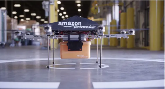
Currently, quadcopter helicopters are used for research and educational purposes. Recommendations have been made for the use of quadrotors for a variety of purposes including search and rescue, surveillance, and package delivery. Figure 2.7 displays a quadrotor helicopter Amazon hopes to implement in the near future for home delivery.
Figure 2.7: Amazon looks to use quadcopter drones to deliver packages in the near future.
Quadrotors are at the cusp of the ability to be used for intelligence gathering. One quadrotor developed by DJI, a company out of Hong Kong, is developed for recording aerial shots for filming companies [22]. Hobbyists also use the AR Parrot Drone to film home videos.
2.3 Chapter Summary
While there are a multitude of autonomous vehicles currently in production today, there are limited technologies in place for data sharing between autonomous agents. This project will address these shortcomings, and explore the benefits of this collaborative decision-making.
3
Principles of Autonomous Vehicles
There are several challenges that must be considered when working with autonomous vehicles. These include the environment in which the vehicle will be operating, the type of vehicle, the motion constraints of the vehicle, and the sensors the vehicle will use to sense the environment and sense its movement in the environment. In addition, methods of analyzing the data collected to detect obstacles in the environment and to determine the current location of the robot in the environment must be considered. Finally, this analyzed data must then be used to make decisions about the movement of the robot within the environment. All these elements are discussed in this chapter.
Figure 3.1: This is a concept diagram for a generic independent autonomous agent. This diagram assumes that all of the agent's data collection and processing is done onboard, and that the agent does not collaborate with other autonomous
3.1 External Sensing
In order for an autonomous vehicle to navigate its environment, it must be able to sense and perceive the environment in a meaningful way. The specific tasks or environments expected to be encountered may dictate the exact choices of sensor or system organization, but the general sensor systems for autonomous vehicles involve perceiving the environment and determining what is an obstacle or objective, or assisting the vehicle in tracking its movements through the environment. Sensing can be performed either actively or passively. Passive sensors function as self-contained measurement instruments. They are used to perceive an aspect of the environment or the system’s relation to the environment without broadcasting or emitting any form of radiation. Active sensors function by emitting a known signal and sensing how the signal is influenced by the environment. The most common type of active sensing is time of flight, wherein the round trip time of a known pulse or burst is measured, and is used for distance measurement and object tracking. Other approaches include measuring the change of a constant (not pulsed) signal. These include “structured light” sensors and some types of radar. Active sensors are often prone to interference in some manner, be it from uncontrollable environmental factors like weather or from one another when used multiple times on the same platform or in a given space.
An inertial measurement unit (IMU) can be a critical component in an autonomous system as it can be used to monitor the motion and orientation of the system where other sensors may fail to produce an accurate reading. IMUs have become popular components in consumer electronics like smartphones and video game consoles in the recent years for interacting with software through motion. An IMU can measure up to six degrees of freedom, and software can calculate change in position and orientation of a robot based upon these readings.
The six degrees of freedom refer to the three axes of linear motion along the X, Y, and Z axes, as well as rotation around each of the axes referred to as roll, pitch, and yaw. Typically, motion in these six degrees of freedom is combined over time to determine sensor position, speed, or orientation.
The current, popular iteration of this mechanism is the combination of a solid-state accelerometer and gyroscope. These systems are built as integrated circuits and referred to as MEMS ICs, and are small enough to be built into cell phones and video game equipment. By carefully integrating the angular velocity reported by the gyroscope and double-integrating the linear acceleration, accuracy of a MEMS-based IMU can be maintained for short periods of time, but the total noise can still induce drift or jitter into a reading.
Table 3.1: Comparison of hobbyist-grade IMU modules to a commercial, automotive-grade module. Hobbyist-grade IMUs typically perform a power-on calibration, but noise and overall calibration need to be performed by the user.
Often, noise cancels out additional precision from additional ADC bits.
Pololu [23] MinIMU-9 v2
SparkFun [24] 9DOF Sensor Stick
Honeywell [25] 6DF-1N6-C2-HWL Accelerometer
Technology MEMS (LSM303DLHC) MEMS (ADXL345) MEMS
Resolution 16-bit ±2g, ±4g, ±6g, or ±8g 13-bit ±2g, ±4g, ±8g, or ±16g >12-bit ±6 Gyroscope
Technology MEMS (L3GD20) MEMS (ITG-3200) MEMS
Resolution 16-bit ±250, ±500, or ±2000 °/s 16-bit ±2000 °/s >12-bit ±75°/s Magnetometer Technology (LSM303DLHC) (HMC5883L) N/A
Resolution ±1.3 to ±8.1 gauss 16-bit ±1 to ±8 gauss 12-bit
Sample rate Up to 100 Hz Up to 100 Hz 1 – 100 Hz
Connectivity I2C I2C SAEJ1939 CAN
Voltage input 2.5 – 5.5V 3.3 – 16V 7 – 32V
Features
Bare board Bare board IP67 or IP69k
weatherproofing Factory calibrated
One drift compensation mechanism is to incorporate a multi-axis magnetometer into both the system and the orientation calculations. A magnetometer reports the sensor’s absolute position relative to magnetic north, and can provide a suitable absolute reference for Z-axis rotation to help eliminate large accumulations of gyroscope drift. Another method is to accumulate the error over an extended period of time and attempt to compensate for it in software. A third method is known as “case flipping” and involves physically inverting the IMU at a fixed interval, causing the drift to accumulate in the opposite direction.
A camera is one of the most relatable types of sensor for a vehicle, as human operation of a similar system is often driven by what the human could see in its surroundings. Most sensors, be they active or passive, do not determine aspects of objects like color or brightness, and thus necessitate either an environmental supplement to allow a robot to coexist with humans, or a way to interpret the world as a human would. Such an example is the self-driving car, navigating a highway or other paved road among human-controlled cars. Features like brake lights and the lines painted on the road surface would go unnoticed by nearly every other kind of sensor available. Observing an adjacent wall could indicate if the vehicle is following the road and tracking the vehicle’s current speed, and distance behind the car in front of it could be used to determine whether or not the brakes need to be engaged. These alternate approaches may work in some environments, but by removing the wall or the car in front, such a system would need either additional non-visual supplements to follow the lines, adding complexity and cost, or could be replaced with a camera.
Two main types of image sensor exist in commercial products: CCD (Charge Coupled Device) and CMOS (Complementary Metal-Oxide Semiconductor). These perform the same task, but have different advantages both in their own technology and the design of an individual
sensor. Pixels in CCD image sensors are charged when struck by light, and converted to voltage and digitized one at a time across the surface of the sensor. CMOS sensors have circuitry attached to each pixel in the sensor to convert the light received to a voltage, and then these voltages are read off. CCD sensors can encounter smearing vertically and horizontally in the presence of bright light sources, affecting large areas of the image, but CMOS sensors can experience distortions in the image called “rolling shutter” if the capture circuitry is slow. Small sensors of both varieties do not receive as much light as large sensors, which negatively impacts their low-light performance, but CMOS sensors generally have better low-light response than CCD sensors.
Multiple cameras around the vehicle (or a camera on a movable platform) can not only be used to further increase the field of view of the processing equipment, but can also be used to emulate human depth perception when oriented in the same direction and separated slightly. Human depth perception works by determining the slight differences in the images received by the eyes, referred to as parallax. Comparing the features of two stereo images captured from cameras can achieve similar results, and properly calibrated and synchronized cameras can be used to capture very accurate depth data. Calculating parallax between camera frames can also be used to determine motion of the attached system within a feature-rich environment.
Stereo vision has its appeal largely due to its relatively low cost ($100 or less) for its performance as a 3D depth sensor when compared to that of active structured light mapping sensors ($1,000) or compounded Lidar modules ($10,000 and up), or in environments where the environment’s ambient radiation would otherwise interfere with an active sensor’s measurements. Natural-light cameras are limited to use only in daylight, however, and by using
infrared cameras and artificial illumination to accomplish the same goal, the sensor system is now classified as an active one.
Stereo vision works by using two cameras that are mounted close together. The direct line of sight of the cameras should be close to parallel. In Figure 3.2, P represents the real word
point that is projected. UL is the project of P in the left image and UR is the projection of P in the
right image. The disparity between these two points can be calculated by subtracting UR from
UL. The depth image can be calculated by Equation 3.1, where f is the focal length of the camera,
and b is the distance between the cameras.
Equation 3.1
𝐷𝑒𝑝𝑡ℎ= 𝑓∗𝑏/𝑑𝑖𝑠𝑝𝑎𝑟𝑖𝑡𝑦
Stereo vision can apply the depth information for use in path planning and obstacle avoidance which will help systems navigate unknown environments [26].
An altimeter measures the altitude of the system to which it is attached. Most digital sensing of altitude is based on a barometer, used to measure the ambient air pressure to determine altitude. These measurements are critical for airborne vehicles, as GPS-based altimeter
Figure 3.2: Diagram of how stereo vision works. This shows how a point from each image can be projected into 3D space [26].
data can be inaccurate, and can use the accumulated Z-axis displacement as a check and source of finer altitude data if necessary. Proper sensing also requires a thermometer to measure the ambient air temperature, as the density of air changes with temperature as well as altitude.
The global positioning system (GPS) allows an autonomous system to determine not where in its environment it is located, but where on the surface of the planet it is located. US Air Force-maintained satellites have been placed into known and controlled orbits around the planet to facilitate this system. Each satellite is equipped with extremely precisely calibrated atomic clocks to maintain accuracy, and constantly broadcasts its time and location in its orbit to the surface, and a line of sight is required to receive it. Once a GPS receiver acquires these signals from at least four of these satellites, the time of flight (at the speed of light) of each message can be determined and the real present time extrapolated. These travel times, along with the satellites' locations, overlap in possible locations such that one point on the Earth in latitude, longitude, and altitude can be determined.
Civilian-grade GPS equipment can determine location down to the scale of meters, but some noise can occur and is expected between measurements, depending on the precision of the hardware and the presence of obstacles obstructing the exact line of sight to the satellite. For more rapid and precise position information, an IMU and appropriate software should be used.
Structured light sensors project a known pattern of light onto a surface or into an environment and record the changes with some form of optical sensor for the purpose of computing the difference between the observed pattern and the known structure to determine distance. A variety of commercially available approaches exist to project the light and record it for analysis, and can provide good depth resolution without an extremely large investment per
sensor. They are typically limited to indoor applications, however, due to their size, operating constraints, or being easily overridden by ambient outdoor light.
Perhaps the most popular construction of structured light mapping device is the 3D scanner. These often use a line of laser light and one or more orthogonally offset cameras to record the shape of the laser as projected on the object being scanned. This approach can be implemented by anyone from hobbyists scanning odds and ends [27] to companies like Shape Fidelity for use in scanning the outside and inside of all of the parts of a Saturn V F-1 rocket engine [28]. These scanners, however, require a known amount of movement to be able to assemble a 3D map of an object or environment from the two-dimensional data a given scan returns.
One of the most popular consumer-oriented implementations of a 3D structured light sensor is the Microsoft Kinect. Developed by PrimeSense, a Kinect broadcasts a unique “speckle” pattern in two dimensions in the IR spectrum and records it with a corresponding IR camera.
Figure 3.3: This speckle pattern is an example from one of PrimeSense’s patent applications [29] for 3D mapping using structured light. This pattern would be repeated when broadcast on a surface. Annotation 92 denotes a light-refracting
bump.
The changes in size and separation of these speckles and their relative intensity are compared to a calibrated baseline to determine the distance to a given point on an object.
Lidar is a depth mapping approach using the time-of-flight of an infrared laser. The laser is pulsed, and the time it takes the pulse to be received by the unit represents the distance to the object. The pulses are emitted at fixed angular increments throughout the sensor’s field of view, and the flight times for those angles can be used to construct a multi-dimensional “scan” of the surrounding area. Most Lidar modules deliver a two-dimensional scan by sweeping through an angle, but several modules and arrangements are capable of providing 3D scans by performing multiple samplings at once (emulating several sensors with slightly offset scans) or changing the angle of a 2D sensor.
Unique speckle pattern
Lidar modules can have ranges up to 100 meters, with results accurate to centimeters or millimeters even in bright outdoor situations, given a high reflectivity of the surface of the object. These sensors are typically expensive due to the precise timing required, for instance accuracy to 1 cm resolution requires timing accuracy down to about 330 picoseconds.
Table 3.2: Comparison of different Lidar modules currently available. Hokuyo URG-04LX-UG01 [30] SICK LMS111-10100 [31] SICK LMS511-10100 PRO [32] Velodyne HDL-64e S2 [33]
Application Indoor Outdoor (IP67-rated housing) Outdoor (IP67-rated housing) Outdoor (IP67-rated housing) 2D/3D 2D 2D 2D 3D Points per scan 683 1080 or 590 1140, 760, 570, 380, 285, or 190 86,000 Scans per second 10 25 or 50 25, 35, 50, 75, or 100 5 to 15 Field of view 240° 270° 190° Horizontal: 360° Vertical: +2°/-24.8° Operating range
0.02 – 5.6 meters 0.5 – 20 meters 1 – 80 meters 120 meters
Angular resolution 0.352° 0.25° or 0.5° 0.167°, 0.25°, 0.333°, 0.5°, 0.667°, or 1° Horizontal: 0.09° Vertical: 0.4° Linear accuracy <1m: ±30mm >1m: ±3% ±30 mm (typical) <10 m: ±25mm 10-20m: ±35mm >20m: ±55mm ±10 mm (typical) Data connection
USB 2.0 Full-Speed CAN, Serial,
10/100 Mbit Ethernet
CAN, USB, Serial, 10/100 Mbit Ethernet 100Mbit Ethernet (UDP) Price, USD $1,100 $6,943 $10,206 $75,000 Product image [34] [31] [32] [35]
Commercially available products can vary widely in price and capability. Hokuyo makes a small, USB-driven model that could be considered suitable for the sophisticated hobbyist or small-scale product. They are capable of indoor and outdoor operation, but have no weatherproofing or fog compensation, and as of this writing still costs $1100 USD or more. SICK manufactures Lidar modules as well, and have been a common choice for past DARPA
Grand Challenge and Urban Challenge vehicles. By comparison, the Google driverless cars, Oshkosh TerraMax, and several DARPA Urban Challenge have used a Velodyne HDL-64E which uses 64 simultaneous lasers for a 28 degree vertical field of view, and rotates them around 360 degrees.
Figure 3.4:Velodyne HDL-64E Lidar module, with cover (left) [35] and without (right) [36]. The top cylinder includes the laser emitters and receivers, and rotates at up to 900 rpm to acquire fifteen full 360 degree, 86,000-point scans per second. Radar works in a similar manner to Lidar in that it measures the time-of-flight of a signal, but radar uses short pulses of microwave radiation instead of IR light. The timing requirements for the detection hardware in a radar system are similar to those of a Lidar module since the microwave radiation also travels at the speed of light. Most radar modules only work well within a given range, as opposed to a Lidar’s ability to work from very close ranges limited to the minimum measurable time of flight to the edges of the laser’s range or the sensor’s sensitivity.
Due to its longer wavelength it can be a more versatile sensor than just time-of-flight distance ranging a Lidar offers. By assembling an array of antennae that are independently controlled, the radar pulses can be not only steered due to constructive and destructive
Laser receivers (32 each)
Laser emitters (4 banks of 16 lasers each)
interference, but the directionality of the antenna is increased to better block out ambient radiation. This implementation is referred to as a “phased array” due to the ability to change the phase of the signal at each antenna, and is typically used more in stationary radar locations.
Automotive radar has currently been on the rise in a number of uses, including adaptive cruise control, lane departure warnings, and automatic crash prevention measures. These are often distinct radar modules due to the limitations of the dynamic range of radar, adding to the cost of the vehicle, but allowing for better sensing across the different applications.
Figure 3.5: Diagram of the radar systems in place in the Mercedes-Benz Intelligent Drive platform [37]. The orange swaths in the image indicate the areas covered by different radar modules.
Figure 2.6 shows the areas covered by different radar modules in a Mercedes-Benz. The close-range and medium-range radars off the front of the vehicle are used for collision avoidance, including possible collisions with pedestrians. The long-range radar off the front of the vehicle detects cars up to 500 meters ahead and is used primarily for “adaptive” cruise control to maintain a set distance to the next vehicle in traffic and a safe following distance. The fields extending out from the rear quarter panels of the vehicle are used to prevent collisions with vehicles in blind spots when changing lanes.
![Figure 1.3: California PATH platooning demonstration in San Diego in 1997. There are 8 Buick LeSabres driving in a platoon, each utilizing V2V communications [8].](https://thumb-us.123doks.com/thumbv2/123dok_us/10945010.2983100/23.918.164.779.106.534/figure-california-platooning-demonstration-lesabres-driving-utilizing-communications.webp)
![Figure 2.1: Team Tartan Racing's Car "Boss", Winner of The DARPA Urban Challenge [57]](https://thumb-us.123doks.com/thumbv2/123dok_us/10945010.2983100/29.918.206.715.105.448/figure-team-tartan-racing-winner-darpa-urban-challenge.webp)
![Figure 2.4: The Google Car equipped with the Velodyne HDL-64e Lidar Module [13].](https://thumb-us.123doks.com/thumbv2/123dok_us/10945010.2983100/32.918.108.799.111.495/figure-google-car-equipped-velodyne-hdl-lidar-module.webp)
![Figure 3.2: Diagram of how stereo vision works. This shows how a point from each image can be projected into 3D space [26].](https://thumb-us.123doks.com/thumbv2/123dok_us/10945010.2983100/41.918.262.664.299.559/figure-diagram-stereo-vision-works-shows-point-projected.webp)
![Figure 3.13: For disk brake systems, the calipers squeeze the brake pads onto the revolving disk, slowing the disk to a stop [44]](https://thumb-us.123doks.com/thumbv2/123dok_us/10945010.2983100/60.918.110.798.111.635/figure-brake-systems-calipers-squeeze-brake-revolving-slowing.webp)