Charles University in Prague
Faculty of Mathematics and Physics
BACHELOR’S THESIS
Roman Betík
XML Data Visualization
Department of Software Engineering
Supervisor: RNDr. Irena Mlýnková, Ph.D.
Study program: Programming
I would like to thank to my supervisor RNDr. Irena Mlýnková, Ph.D. for leading my work. I would also like to thank to my parents and my sister for supporting me during my studies.
I declare that this thesis was composed by myself using only the stated sources. I agree with borrowing and publishing of this thesis.
Contents
1 Introduction 6
1.1 Structure of the Text . . . 6
2 XML Basics 7 2.1 A Brief Introduction to XML Format . . . 7
2.1.1 XML and Namespaces . . . 8
2.2 XML Schema Definition . . . 9
2.3 XML Processing in Programming Languages . . . 12
2.3.1 Document Object Model . . . 12
2.3.2 Simple API for XML . . . 12
2.3.3 Other Methods . . . 13
2.3.4 XML & .NET Framework . . . 13
2.4 XPath Language . . . 13
3 Application Goals 17 3.1 XML Data Visualization . . . 17
3.2 Modifications of the Visualized Structure . . . 18
3.3 Modifications of Appearance of Particular Visualized Elements . . 18
3.4 Element Selection . . . 18
3.5 XML Schema Editing and Creation . . . 18
3.6 Storing of the Edited Documents . . . 18
3.7 Working with Large Documents . . . 18
4 User Documentation 19 4.1 User Interface . . . 19
4.1.1 The Ribbon . . . 20
4.2 XML Document Creation . . . 22
4.3 Loading Existing XML Documents . . . 23
4.4 Editing Properties . . . 24
4.5 Adding Child Nodes . . . 24
4.6 Changing Appearance . . . 25
4.7 Node Removal . . . 26
4.8 Copying and Moving Subtrees of Nodes . . . 26
4.9 Node Selection . . . 26 4.10 DTD Validation . . . 27 4.11 XML Schema Validation . . . 27 4.12 Export . . . 28 4.13 Printing . . . 28 4.14 Settings . . . 28
4.15 XML Schema Creation and Editing . . . 29
4.15.1 Creation . . . 29
4.15.2 Editing . . . 30
5 Architecture of the Application 36 5.1 Introduction . . . 36
5.2 Overview of the Architecture . . . 36
5.2.1 Model-View-Controller Design Pattern . . . 36
5.2.2 Model-View-ViewModel Design Pattern . . . 38
5.2.3 XmlStudio.Common . . . 39
5.2.4 XmlStudio.Model . . . 41
5.2.5 XmlStudio.Main . . . 42
5.2.6 Summary . . . 46
6 Important Algorithms 47 6.1 Handling Large Documents . . . 47
6.2 Saving the Document . . . 50
6.3 Layout Rendering . . . 51
7 Other Solutions 55
8 Summary and Conclusion 57
Title: XML Data Visualization Author: Roman Betík
Department: Department of Software Engineering Supervisor: RNDr. Irena Mlýnková, Ph.D.
Supervisor’s e-mail address: [email protected]
Abstract: The aim of the thesis is to implement a graphical editor designated to create and edit XML documents and documents in XML Schema language. The main part of the work is design and implementation of the program. Created application allows to edit (or create) XML documents using tools to modify par-ticular graphical elements which represent elementary parts of the document (el-ements, text nodes etc.). It also includes support for easier creation of schemas in XML Schema language. It is possible to validate edited XML documents against DTD or XSD schemas. The resulting work can be saved back to its text rep-resentation or the visualization can be saved as an image. The work includes description of application’s architecture and description of the most important parts of the source code.
Keywords: XML, XSD, visualization, planar graph, data, editor, XPath Názov práce: Vizualizácia XML dát
Autor: Roman Betík
Katedra: Katedra softwarového inžinierstva Vedúci práce: RNDr. Irena Mlýnková, Ph.D.
E-mail vedúceho práce: [email protected]
Abstrakt: Cieľom práce je implementácia grafického editoru určeného na vytvára-nie a editáciu XML dokumentov a dokumentov v jazyku XML Schema. Hlavnou časťou je návrh a implementácia programu. Samotný program umožňuje editovať (prípadne vytvárať) XML dokumenty pomocou úpravy jednotlivých grafických prvkov reprezentujúcich elementárne časti dokumentu (elementy, textové uzly atď.). Takisto zahŕňa podporu pre jednoduchšie vytváranie schém v jazyku XML Schema. Editované XML dokumenty je možné validovať voči DTD alebo XSD schémam. Výslednú prácu je možné uložiť spätne do textovej podoby, prípadne si vizualizáciu uložiť ako obrázok. Práca obsahuje popis architektúry programu a najdôležitejších častí zdrojového kódu.
Chapter 1
Introduction
XML language [2] is a commonly used format when sharing data. It is text-based so to create or edit XML documents an editor is needed. Most of the avail-able editors for XML documents are text-based editors. The logical structure of XML documents enables us to go beyond the text representation and create applications which render XML documents in a much user-friendlier way.
The aim of this thesis is to create such an application. This application will be able to load existing XML documents or create new ones and display them in the form of planar graphs [3]. A user will be able to modify this layout by adding or removing elements of an XML document or by changing the visual parameters (like colour or shape) of particular entities. User will also be able to select elements using the language intented for querying XML data. The program will include classical functions every editor should have (detailed list of these feature is included in Chapter 3).
1.1
Structure of the Text
The second chapter describes basic concepts of XML language and XML schemas. This chapter also includes description of basic methods how to work with XML from the view of a programmer. The third chapter describes the goals and requirements of created application. The fourth chapter includes user doc-umentation. The fifth chapter describes the architecture of the application and all major tools and libraries used when building it. The following chapter de-scribes the main algorithms used in this application. The sixth chapter analyzes existing solutions. The seventh chapter summarizes the work. The last chapter, Appendix A, lists the contents of the attached CD.
Chapter 2
XML Basics
2.1
A Brief Introduction to XML Format
XML (Extensible Markup Language) is a general-purpose specification how to create new markup languages. It is extensible because XML allows us to create new markup elements. This format is text based, simple and very flexible.
The main purpose of XML (Listing 1 contains sample XML document) is to make sharing and distributing information between various independent systems easier. It is text based, easily parsed format which is easy to read even by humans. Nowadays it is used not only for storing information but also for data serialization, as data transport format and even for databases.
More about XML can be found at the website of the World Wide Web Con-sortium [1].
<?xml version="1.0" encoding="utf-8"?>
<Program> <Assemblies>
<Assembly name="XmlStudio.Main"> <File Source="MainWindow.xaml" /> <File Source="MainWindow.xaml.cs" /> </Assembly>
<Assembly name="XmlStudio.Model"> <File Source="Models/XmlModel.cs" /> <File Source="Models/ModelFactory.cs" /> </Assembly>
</Assemblies> <Resources>
<Image Source="Images/Icon.ico" /> </Resources>
<RequiredNetVersion version="4.0" /> <Notes>
<Note>XmlStudio’s source code files.</Note> </Notes>
<!-- This is a comment. -->
</Program>
Listing 1: Sample XML document.
There is a prolog at the very beginning of this sample XML document. Every XML file stars with a prolog. It has two parts: the XML declaration, which
is shown in the sample (the minimal requirement is to specify the version) and Document Type Declaration (DTD). DTD is an optional part. More about DTD in the following sections. After prolog there is a root element with nested child elements.
Elements consist of so called tags. An element begins with a start-tag, e.g.
<Program> and ends with an end-tag, e.g. </Program>. There can be text
be-tween these tags (as in the case of element <Note>) which is called the value of the element or another nested tags. When there is no text or no tags between these two tags, you can skip the end-tag and express the whole tag as an empty element, e.g. <RequiredNetVersion />. Element itself is identified by its name, in our sample document there is an element with the name Program.
Elements can have attributes. They appear after the name of the element and have the form of attributeName=”value”. In our sample there is an attribute
name on element Assembly with the value XmlStudio.Main. XML documents may
also contain some comments which are inserted between <!-- and -->.
This sample XML document is well-formed. The XML specification defines exactly what well-formedness is and it can be found here [2]. The key points are that the begin, end, and empty-element tags are correctly nested, with none missing and none overlapping. Element tags are case sensitive, so the start and end-tags must match exactly. There is only one root element which contains all the other elements.
2.1.1
XML and Namespaces
XML language includes the concept of namespaces. When we create docu-ments, we usually create some kind of vocabulary of elements and attributes. If we want to combine more of these created “vocabularies” together in one docu-ment, we might encounter some difficulties with naming. To distinguish these different vocabularies, XML brings namespaces. This is solved with a separate standard [4].
Consider the XML fragments in Listing 2 and Listing 3. <Company> <p>Microsoft Corporation</p> <p>Redmond</p> </Company> Listing 2: XML fragment 1 <Company>
<Name>Microsoft Corporation</Name> <City>Redmond</City>
</Company>
Listing 3: XML fragment 2
If we tried to use these two fragments together in one document, we would get a conflict, because there are elements with the same names but a different
struc-the uniform resource identifier (URI) [5]http://www.microsoft.com/. Because us-ing this long name would be too difficult, there is a shortcut. The shortcut is usus-ing
the prefix for the namespace. So for the namespace http://www.microsoft.com/
there is prefix m which is declared on the root element and then used before
the name of the elements that belong to this namespace. <Companies xmlns:m="http://www.microsoft.com/" xmlns:n="http://www.hotmail.com/"> <m:Company> <m:p>Microsoft Corporation</m:p> <m:p>Redmond</m:p> </m:Company> <n:Company>
<n:Name>Microsoft Corporation</n:Name> <n:City>Redmond</n:City>
</n:Company> </Companies>
Listing 4: Naming conflict solved
2.2
XML Schema Definition
The structure of an XML document can vary a lot and therefore there are many different ways how to express the same information. This might not be a problem for people but this could prevent correct communication between dif-ferent computer systems. Therefore it is a good practice to create a set of rules for your document which defines what elements and attributes are allowed. This way both communicating sides know what to anticipate and can prepare their application logic accordingly.
There are several languages designated for XML schema definition, for in-stance DTD [6] (Document Type Definition, Listing 5 contains sample DTD), XML Schema [7] (Listing 6 contains sample XSD), Relax NG [10] or Schema-tron [11]. Any of these languages itself would need many pages to describe so in case the reader is interested in these languages we leave him to find detailed information about these topics himself.
<!DOCTYPE Program [
<!ELEMENT Program (Assemblies, Resources, RequiredNetVersion, Notes?)>
<!ELEMENT Assemblies (Assembly+)>
<!ELEMENT Resources (Image*)>
<!ELEMENT RequiredNetVersion EMPTY>
<!ATTLIST RequiredNetVersion version CDATA #REQUIRED>
<!ELEMENT Notes (Note*)>
<!ELEMENT Note (#PCDATA)>
<!ELEMENT Assembly (File+)>
<!ATTLIST Assembly name CDATA #REQUIRED>
<!ELEMENT File EMPTY>
<!ATTLIST File Source CDATA #REQUIRED>
<!ELEMENT Image EMPTY>
<!ATTLIST Image Source CDATA #REQUIRED>
]>
The sample DTD contains schema declaration for the document in Listing 1.
This DTD means that the root element must be elementProgram. Then there are
definitions for elements and their content. The construct <!ELEMENT ... > de-fines the content of the element which name is after the keyword ELEMENT. There are various options you can use when declaring what content can be inside the el-ement. The next construct is <!ATTLIST ... > which defines what attributes are valid for the specified element. For the complete instructions about how to write a DTD see its specification.
The sample in Listing 6 contains XSD schema for our sample XML document. Every XML schema is also an XML document which only contains specially defined set of elements. As you can see in the sample, the root element of XML schema must be element schema. The rest of the schema are special elements and attributes which define it.
The simplest elements of XML schema language are the simple types. Our sample does not contain any simple type but in short, when element or attribute is of a simple type, it means that it can have only text content. But this text content can be constrained in various ways. Simple types are either built-in data types [8] or user defined data types [9]. On the other hand, when an element has been assigned a complex type, this element can contain other elements and also attributes (if the type specifies them). Our sample contains some complex types.
For example element Notes has been assigned a complex type which contains
a sequence of elements Note.
To describe every aspect of XML schema, we would need much more space. Therefore we leave the details out and if the reader is interested, the complete reference can be found in XML Schema specification [7].
<?xml version="1.0" encoding="utf-8"?>
<xs:schema xmlns:xs="http://www.w3.org/2001/XMLSchema"> <xs:element name="Program">
<xs:complexType>
<xs:choice minOccurs="0" maxOccurs="unbounded"> <xs:element name="Assemblies">
<xs:complexType> <xs:sequence>
<xs:element name="Assembly" minOccurs="0" maxOccurs="unbounded"> <xs:complexType>
<xs:sequence>
<xs:element name="File" minOccurs="0" maxOccurs="unbounded">
<xs:complexType>
<xs:attribute name="Source" type="xs:string" />
</xs:complexType>
</xs:element>
</xs:sequence>
<xs:attribute name="name" type="xs:string" /> </xs:complexType>
</xs:element> </xs:sequence> </xs:complexType> </xs:element>
<xs:element name="Resources"> <xs:complexType>
<xs:sequence>
<xs:element name="Image" minOccurs="0" maxOccurs="unbounded"> <xs:complexType>
<xs:attribute name="Source" type="xs:string" /> </xs:complexType>
</xs:element> </xs:sequence> </xs:complexType> </xs:element>
<xs:element name="RequiredNetVersion"> <xs:complexType>
<xs:attribute name="version" type="xs:string" /> </xs:complexType>
</xs:element>
<xs:element name="Notes"> <xs:complexType> <xs:sequence>
<xs:element name="Note" type="xs:string" minOccurs="0" /> </xs:sequence> </xs:complexType> </xs:element> </xs:choice> </xs:complexType> </xs:element> </xs:schema>
2.3
XML Processing in Programming Languages
2.3.1
Document Object Model
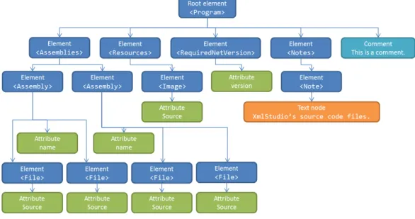
Document object model (DOM) [12] is a language-independent interface for object oriented programming languages (or script languages). It provides develop-ers with methods to access and modify the structure of XML documents. XML processor (or parser) generates virtual tree-like model of the entire document which is then stored in memory. This implies limits on its usage. XML doc-uments which object model would not fit into memory cannot be accessed and modified using DOM. Therefore this method is suitable for smaller documents (approximately 0B - 10MB, the upper limit is determined by the implementa-tion of DOM and available system memory). This interface is available for many languages, such as C++, Java, JavaScript, CORBA, C# etc. Figure 2.1 shows an example of DOM hierarchy of our sample in Listing 1.
Figure 2.1: XML DOM tree hierarchy
2.3.2
Simple API for XML
Simple API for XML (SAX) [13] is a programming interface based on events. XML parser reads the document and when it encounters any significant items (start-tag, end-tag, text node etc.) it raises an appropriate event. A programmer needs to subscribe for these events using event handlers. These event handlers can be programmed to do any desired actions the programmer needs. This provides the developer with forward-only access to XML document. This also limits its usage. The programmer has to know what to do precisely because he cannot jump from one node to another randomly. The advantage is that the whole document does not have to be stored in memory and leaves much smaller memory footprint. This makes it a great tool for processing huge XML documents which can be hundreds or thousands of megabytes in their size while preserving small memory
1) startDocument() - beginning of the document
2) startElement() Program - beginning of the element
3) startElement() Assemblies
4) startElement() Assembly - also provides attributes
5) ...
6) endElement() Assembly
7) startElement() Assembly
8) ...
9) endDocument() - end of parsing the document
Listing 7: Example of SAX events
2.3.3
Other Methods
DOM and SAX are the most common ways of accessing and processing XML documents programmatically. All other methods are just their variations. Differ-ences are mostly in their implementation or programmatic usage.
2.3.4
XML & .NET Framework
.NET Framework [14] contains two main APIs which deal with XML. Their
implementation is placed within System.Xml namespace.
The first API is based on the classXmlDocument[15], which implements the W3C Document Object Model (DOM) Level 1 Core and the Core DOM Level 2. This
API contains more classes which model the DOM, like XmlNode, XmlElement,
XmlEntity, XmlAttribute and so on. Each of these classes represents the
cor-responding XML part or entity and contains methods to modify and create these XML parts.
The second approach is similar to SAX. XmlReader and XmlWriterare classes
which provide us with this SAX like API (to be precise more like Streaming API for XML, StAX [16] because it is pull-based). With these classes we are able to read and write documents that do not fit into memory at once.
There is also a third option, quite new technology called LINQ to XML [17]. But it is only rewritten object model for XML using old API and modified to be queryable using LINQ [18], so we can say it falls into the first category. Creation and manipulation of XML documents using this new API is easier and less com-plicated in comparison to XmlDocumentand related classes. It has been placed in the namespace System.Xml.Linq. More about all of these classes can be found in MSDN library, inSystem.Xmlsection1 andSystem.Xml.Linqsection2 namespaces.
2.4
XPath Language
XPath [19] is a language for addressing parts of an XML document. XPath uses expressions to select nodes in an XML document. The following list sum-marizes expressions that can be used:
• nodename – selects all child nodes of the named node
1http://msdn.microsoft.com/en-us/library/system.xml.aspx 2http://msdn.microsoft.com/en-us/library/system.xml.linq.aspx
• /– selects the root node
• //– selects nodes from the current node that match the selection regardless of their position
• . – selects the current node
• .. – selects the parent node of the current node • @– selects attributes
The following list shows some basic path expressions and their results:
• Program– selects all the child nodes of the Programelement
• /Program – selects the root element Program
• Assemblies/Assembly – selects all Assembly elements that are children of
element Assemblies
• //File – selects all File elements regardless of their position in the
docu-ment
• Program//File– selects allFileelements that are descendants of theProgram
element
• //@Source– selects all attributes named Source
Predicates
Predicates in XPath are used to find specific nodes. They are always embed-ded in square brackets. The next example shows some simple predicates:
• /Program/Assemblies/Assembly[1]– selects the first Assemblyelement that
is the child node of the Assemblies element which is the child node of
the Program element
• Assemblies/Assembly[last()] – selects the last Assembly element that is
the child of the Assemblies element
• //File[@Source] – selects all the File elements that have an attribute
Source
XPath Wildcards
XPath wildcards are used to select elements that are unknown.
• *– matches any element node
• @* – matches any attribute node
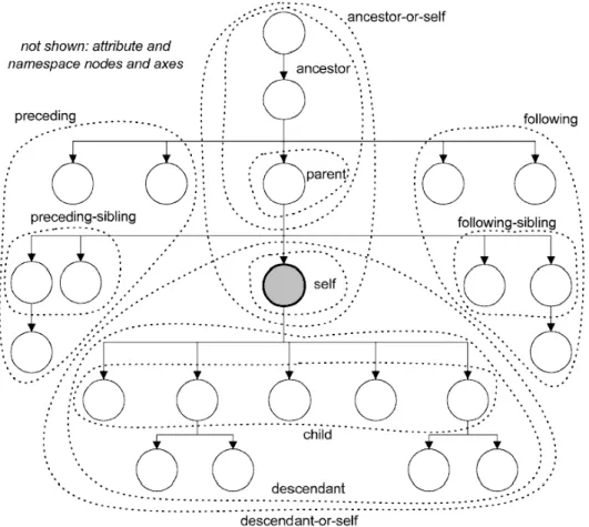
XPath Axes
XPath axis defines a set of nodes relative to the current node. The following list summarizes them:
• ancestor – selects the ancestors of the current node (parent, granparent,
etc.)
• ancestor-or-self– selects all ancestors of the current node and the current
node itself
• attribute– selects all attributes of the current node
• child– selects all children of the current node
• descendant – selects all descendants of the current node
• descendant-or-self– selects all descendants of the current node and the
cur-rent node itself
• following– selects everything after the end tag of the current node
• following-sibling – selects all siblings after the current node
• namespace– selects all namespace nodes of the current node
• parent – selects the parent node of the current node
• preceding– selects everything before the start tag of the current node
• precesing-sibling – selects all siblings before the current node
• self – selects the current node
For better overview of XPath axes, see Figure 2.2.
Location Path Expression
Axes are used in location paths. They are absolute or relative. An abso-lute location path starts with a forward slash (/), a relative without the slash. The location path consists of one or more steps, e.g. absolute location path might look like this: /step/step/step/.... Every step consists of an axis, a node test (which identifies a node within axis) and zero or more predicates. The
syn-tax for one step is as following: axisname::nodetest[predicate]. For example
child::text() selects all text child nodes of the current node.
The result of an XPath expression can be a node set, a string, a boolean or a number.
For complete information about XPath language, see the specification of the XPath language [19].
Chapter 3
Application Goals
Application created as an objective of this thesis is called XmlStudio. From now on when refering to this application, we use the name XmlStudio.
Main goals of XmlStudio application are the following points: • XML data visualization.
• Modifications of the visualized structure.
• Modifications of appearance of particular visualized elements. • Element selection.
• XML Schema editing and creation. • Storing of the edited documents. • Working with large documents.
3.1
XML Data Visualization
XmlStudio is an application for graphical manipulation, visualization and editing of XML documents. Graphical means that the user is not forced to edit the source code of the document but he gets a visual representation of the XML tree. Every element of a document, if it is an element or a text node, is rep-resented with a separate graphical entity and these are connected according to the structure of the document. These connections emphasize the parent-child relationships.
XmlStudio creates the visual representation of XML document using simple interconnected graphical elements layed out on canvas. XmlStudio uses simple algorithm (which renders XML document as a tree) to layout the tree structure of XML document so the user gets a clear view of how the structure looks like. This view makes it much easier to grasp it.
3.2
Modifications of the Visualized Structure
XmlStudio enables editing of every element, its properties like name or names-pace and its attributes. It is possible to add or remove elements from the doc-ument thus allowing modifications of the tree hierarchy. Whole subtrees can be copied or moved to another place in the document’s tree. Single elements can be moved in their layer between their siblings (because order of elements is significant).3.3
Modifications of Appearance of Particular
Vi-sualized Elements
Another goal is to provide users with easy modifications of rendered elements, mostly changing the shape or colours of selected items. Any shape, background and border colour can be modified as the user wishes.
3.4
Element Selection
XmlStudio offers selection filter to select any set of elements in currently rendered tree. There is a language for addressing parts of an XML document called XPath [19]. XmlStudio uses this language for element selection.
3.5
XML Schema Editing and Creation
XmlStudio is also able to create and edit schemas in XML Schema language. Using predefined sets of allowed elements and attributes, XmlStudio makes it easier for users to create or edit schemas. XML Schema language is one instance of the XML. Module which works with XSD benefits from all the tools available for generic XML documents so when user learns how to use tools for generic XML editing, learning XSD part is really easy (assuming the user knows XSD).
3.6
Storing of the Edited Documents
XML documents (or XSD schemas) can be saved back to the text format, exported to various image formats and sent to the printer.
3.7
Working with Large Documents
The last but important objective is to be able to work with very large docu-ments which cannot be loaded into memory at once. XmlStudio makes it possible via simple expansion method (described in Chapter 6) which allows to load only certain parts of the document. All these features are described in more detail in the following chapters.
Chapter 4
User Documentation
XmlStudio offers tools to create and edit XML documents and XSD schemas. The following sections describe in detail what and how you can achieve with XmlStudio.
4.1
User Interface
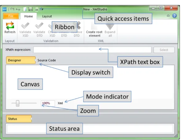
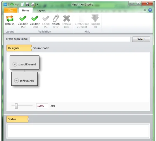
Figure 4.1: Main window
Figure 4.1 shows the main window of XmlStudio. It contains the following parts:
• Quick access items – the most frequently used commands can be added here • Ribbon – the main toolbar
• XPath text box – input area for XPath queries
• Display switch – switches between Designer mode and Source code mode;
Source code mode shows the source code of currently loaded document,
however, it is read-only
• Canvas – the main working area
• Mode indicator – indicates whether the current document is being edited
inXML orXSD mode
• Zoom – enables to zoom-in or zoom-out the canvas
• Status area – warnings and error messages from validation (DTD or XSD) are displayed here
4.1.1
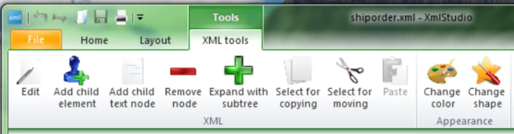
The Ribbon
XmlStudio uses special interface called ribbon [31] where toolbars are placed on tabs. Ribbon was introduced by Microsoft 1 in Microsoft Office 20072. Xml-Studio uses open source implementation called Fluent Ribbon Control Suite [29] which is targeted for Windows Presentation Foundation applications [26].
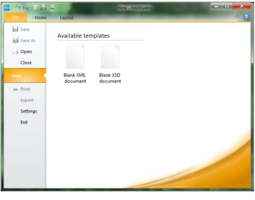
The ribbon has a special part called backstage which you can see when you click on tab File. Backstage area of XmlStudio is shown in Figure 4.2.
Figure 4.2: Backstage There are several buttons:
1
• Save – saves the document to a file
• Save As– saves the document to a file with a chosen name
• Open – opens the document
• Close– closes the current document
• New – shows options to create either blank XML document or blank XSD
document
• Print– shows dialog window with printing options
• Export– shows dialog window with options to export the current document
to various image formats
• Settings – shows Settings dialog
• Exit – terminates the application
The Home tab (see Figure 4.3) contains the following commands:
Figure 4.3: The Home tab
• Refresh– recalculates and redraws the rendered graph
• Validate XSD – tries to validate the document against XSD; it validates
successfully only if XSD is attached inside the document
• Validate DTD – tries to validate the document against DTD; it validates
successfully only if DTD is attached inside the document
• Check XSD– this command is disabled in XML mode
• Attach DTD– allows to attach external DTD to the current document, note
that if there was DTD already specified, this replaces it
• Remove DTD – removes attached DTD
• Create root element – this command is available only when there is no
root element in the document (when the document is empty); if enabled, it provides the user with dialog to create new root element
• Expand all – if this command is enabled, it makes it possible to expand
all collapsed nodes in the document (warning: use this command only for small documents, expanding too many nodes leads to poor performance) The Layout tab contains some basic settings for layout algorithms used in XmlStudio. Figure 4.4 contains settings for Simple tree layout algorithm.
Figure 4.4: The Layout tab
4.2
XML Document Creation
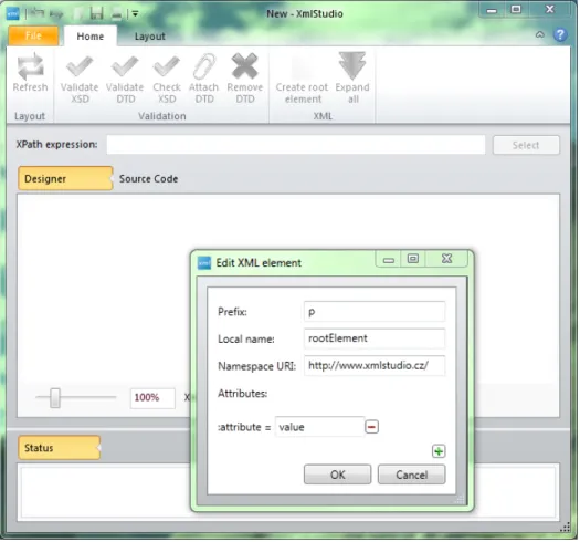
With XmlStudio you can create new XML documents. You need to follow simple steps to achieve it. First you need to start XmlStudio. Then you can start inserting new elements. Right-click on the canvas and select Create root
element or click on Create root element command. The dialog, where you can
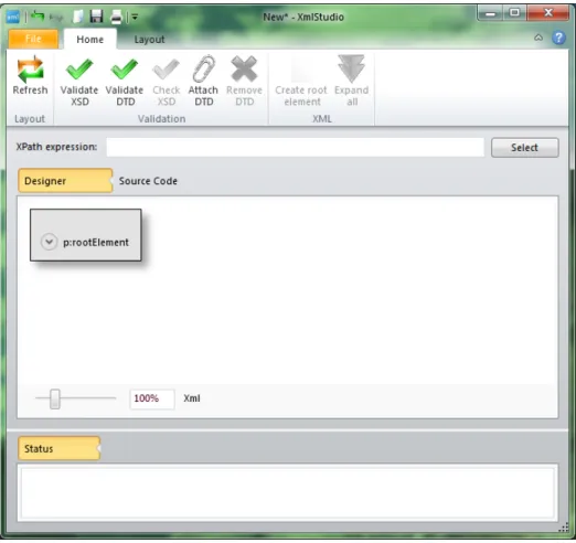
enter the name (prefix, namespace) of the element, add some attributes if desired, pops up. When you are done with setting the properties of this new element, click OK and the element will appear on canvas. Figure 4.5 shows dialog with the new root element and Figure 4.6 shows the inserted root element.
Figure 4.5: Root element creation
With root element added, there are several step we can take: • Edit properties of just added element.
Figure 4.6: Added root element • Add child text node(s).
• Change colours or shape of the visualized element. • Remove the element.
4.3
Loading Existing XML Documents
To open an existing XML document, click on Open command from the
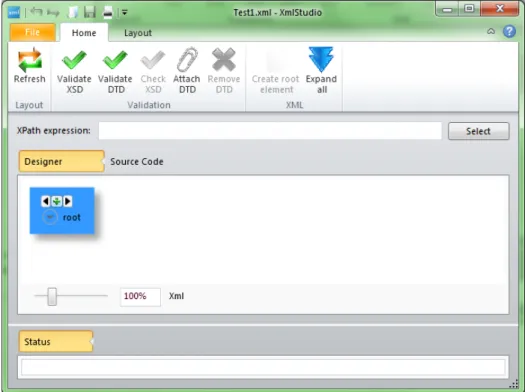
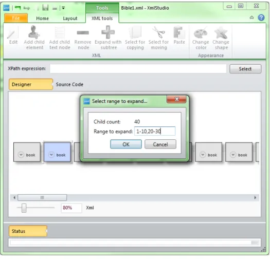
back-stage area. After selecting the file, the root element of the existing document is loaded in XmlStudio. This situation is shown in Figure 4.7. If the mouse cursor is over the root element, the small plus button is visible. This button serves to expand the element. If the element contains less than some number of child ele-ments (this number can be set in settings of XmlStudio), the element is expanded right after clicking on this button. If there is more than the set number, the dia-log pops up. In this diadia-log you can specify the range of child elements to expand. This range is expressed as a string, e.g. to expand first ten child elements and then elements from twenty to thirty, the range should be 1-10,20-30. The dialog also displays the number of child elements of the element to be expanded. All this is shown in Figure 4.8. To expand all child nodes simply leave the text box empty.
If you did not expand all children you still can do so by clicking the plus button and specifying the remaining range or leaving the text box empty (which
will expand all child nodes). You can also collapse the expanded node by clicking
the minus button.
When you know the document contains smaller number of elements (e.g. less than few hundreds), you can skip expanding single elements and you can use
the Expand all command from the ribbon. This will load the whole document
into XmlStudio and render every node. Use this command with caution because loading huge documents will practically freeze the application.
Huge documents should be expanded with caution. You should expand only those branches or elements which you need to work with. All other parts of the document can stay collapsed.
Figure 4.7: Opening an existing file with root element loaded
4.4
Editing Properties
To edit properties just right-click on the element and select Edit. The same dialog window as for adding root element pops up. There you can edit whatever
properties you wish, then confirm your changes with OK button or cancel them
withCancelbutton. The second approach is to use the contextual tab which opens
when a node is selected. This tab is shown in Figure 4.9. To edit the element, select it and then click Edit button in ribbon.
4.5
Adding Child Nodes
To add a new child element, right-click on the element and select Add child
Figure 4.8: Expanding an element
by clicking OK. Figure 4.10 shows the added child element on canvas. The child element is connected to its parent with a line ended with an arrow. This empasizes the parent-child relationship. You can also use command from the contextual
toolbar in ribbon as in the previous case. Use the Add child element button
after selecting the desired element.
To add new text element, simply selectAdd child text nodefrom the context menu of the parent element. In the dialog box insert the text which should be the content of the new text node and click OK. The new text node appears under
its parent. The same can be done using theAdd child text nodecommand from
the ribbon.
4.6
Changing Appearance
To change the colour or shape of selected items (elements or text nodes), first select them either by dragging the rectangle around them or by clicking on them while holding theCtrlkey. When you have selected all items you want, right click
on any of them and chooseChange colorsorChange shapefrom the context menu
(depending on what you want to change). The dialog box will appear. There you either change the colours or the shape of the element. As usual, confirm your action by clicking OK. Figures 4.11 and 4.12 show these two dialogs. Another way of doing the same is choosing the appropriate commands from the ribbon as in previous cases.
Figure 4.9: Tab with contextual tools
4.7
Node Removal
To remove the node (element or text node), select Remove nodefrom the con-text menu. There will be a dialog asking you if you want to delete the whole subtree with the selected node. If you choose yes, the element and all its descen-dant nodes will be removed from the document. If you choose no, only the se-lected node will be removed and the child nodes of this node will be added where the removed node resided. If removed node had more than one child, all of these children will be moved to the higher level and become the child nodes of the for-mer parent of the removed node. The same can be achieved using the command
Remove node from the ribbon.
When the document consists of many elements, there are three functions which can help with copying or moving the whole subtrees.
4.8
Copying and Moving Subtrees of Nodes
The first two operations require two steps. The first step is to select the root
element of the subtree which you want to copy (chooseSelect for copying from
the context menu or from the ribbon) or move (choose Select for moving from
the context menu or the ribbon). Then select the element which should be the des-tination of the operation, the new parent of copied (moved) subtree. Then choose
Paste subtreefrom the context menu (orPastefrom the ribbon) and the subtree
will be copied (or moved) to the desired destination. Figure 4.13 and Figure 4.14 show the process of moving a subtree and Figure 4.15 shows the result.
The third operation is changing the order of a node among its siblings. Every visualized item has two small arrows (Figure 4.16) visible when the mouse is over it. Using these two arrows, it is possible to change the order of this node. It can be moved one item to the left or to the right. The content of the moved node does not change, all descendant nodes are moved with its parent.
4.9
Node Selection
XmlStudio benefits from XPath language and uses it to select nodes in the loaded document. To select nodes according to your XPath query, type in the query to the text box as shown in Figure 4.17 and clickSelect. The nodes selected by the query will get selected.
Figure 4.10: Added child element
that can be a result of an XPath query), write the query, select those items and then you can easily change visual properties of those items.
4.10
DTD Validation
There are two ways to validate existing document against DTD. If the current
document already contains DTD, the validation can be done using the Validate
DTDcommand from the ribbon. This will scan the document and report any errors or warnings to the status area.
If the document does not contain DTD declaration, you can add one using
the Attach DTDcommand. It will prompt you to locate the file with DTD (please
note that the current version of XmlStudio requires the DTD to be located in the same directory as the XML document) and it will automatically add the DTD
declaration. Then the command Validate DTD works as in previous case.
4.11
XML Schema Validation
To validate the document against XSD, there already has to be XSD specified inside the XML document. This can be achieved using the standard editing tools available in XmlStudio (adding attributes) so there is no special tool for this
Figure 4.11: Dialog for changing the colours violating the XSD.
4.12
Export
The visualized XML document can be saved to one of the following image for-mats: JPEG, BMP, PNG, TIFF, GIF, XPS. To export the current visualization,
click on the Export command in the backstage area.
4.13
Printing
The visualized XML document can also be sent to the printer. To do so, click
on the Printcommand in the backstage area.
4.14
Settings
XmlStudio offers some preferences that can be changed. The Settings dialog is displayed after clicking on Settings item in the backstage area. The dialog (see Figure 4.18) contains three tabs: General, Colors and XML. General tab contains the language selection. The user interface of XmlStudio is available in three languages: American English, Slovak and Czech. The next tab, Colors
Figure 4.12: Dialog for changing the shape
(Figure 4.19), provides settings for default colours used by the application when rendering elements and text nodes.
4.15
XML Schema Creation and Editing
4.15.1
Creation
To create XML schema using XmlStudio, you need to create new blank doc-ument by clicking New in the backstage area and selecting Blank XSD document. XmlStudio is now in XSD mode and you can start creating new XML schema.
The process of creating the schema is similar to creating the generic XML doc-ument. First you need to add the root element. XmlStudio fills the name, prefix and namespace of the element for you because the root element must be the
el-ement schema in the namespace http://www.w3.org/2001/XMLSchema. The prefix
on the other hand can be changed to anything you want, default is xs. After
adding the root element, you can add child elements. The context menu gives you the list of all the elements that can be inserted as a child of the element
schema. The example for the element schema can be seen in Figure 4.20.
This way the XML schema can be created from scratch. However, the context help currently does not take into account already inserted elements, so it always offers all the available elements as if the parent element had no children.
Figure 4.13: Moving the subtree, the first step
XSD schema. This tool is available from the ribbon and is called Check XSD. All the errors and warnings from this tool are reported to the status area.
4.15.2
Editing
If you open an existing XSD, it is loaded and displayed in the same manner as the generic XML document. You can expand and collapse elements as desired. You can also edit the element and their attributes, edit the structure by adding or removing elements etc. The only difference is that if you edit elements in XSD mode, the editing dialog offers you customized environment.
Figure 4.21 shows a dialog window when editing elementrestriction. Dialog box editing attributebasecontains the list of available data types that can be set as a base type. This list contains built-in data types and every named data type already defined in this schema. The similar value lists are available also when editing element attribute (attributes ref and type), attributeGroup (attribute
ref),element(attributesref,typeandsubstitutionGroup),extension(attribute
base), group(attribute ref), keyref(attribute refer),list (attribute itemType)
and union (attribute memeberTypes).
The rest of the tools works the similar way as in XML editing mode (including appearance changing, exporting, printing, etc.).
Figure 4.14: Moving the subtree, the second step
Figure 4.16: Arrows to change the element order
Figure 4.18: Settings
Chapter 5
Architecture of the Application
5.1
Introduction
The architecture of XmlStudio is based on separation of concerns. It means that the whole application is divided into set of modules where every module offers an encapsulated set of functions. This approach helps to keep the entire application maintainable during its life and easier to comprehend by other pro-grammers.
When writing small applications using this technique, it might seem that it prolongs the development time (application is more complex than it would be when written the most straightforward way). It is often true but in the longer horizon any major changes require much more time and effort because the applica-tion was not written to be extendable. When deciding how to design XmlStudio, we took these questions into consideration and tried to make the best of it.
5.2
Overview of the Architecture
XmlStudio is written in C# language using .NET Framework 4 1 as a
de-velopment platform. The application consists of three main parts (assemblies) as shown in Figure 5.1. These modules are the result of used design patterns. The overall architecture is inspired by the MVC (Model-View-Controller) and the MVVM (Model-View-ViewModel) design patterns described in [23] and [24].
5.2.1
Model-View-Controller Design Pattern
Model-View-Controller is one of the compound design patterns used in soft-ware development. This pattern requires three parts: Model, View and Controller as you can see in Figure 5.2. The main advantage of this pattern is object decou-pling. It means that Model does not depend on the View (user interface/presen-tation layer) or the Controller and vice versa. In other words if the programmer decides to change the presentation layer of the application he does not need to do any major changes in the Model (if the pattern is followed properly).
This design pattern however requires some overhead in the application which is mostly caused by the need for every call from the user interface to go through
Figure 5.1: Main program modules
Figure 5.2: Model-view-controller
the Controller and then to the Model. But the benefits of this pattern overweight the disadvantages. It provides us with three independent units and guides us to write better encapsulated objects. It means easier future changes in the code and easier maintenance of the application.
The Model
The Model holds all the state data and application logic. It does not de-pend on the View or the Controller. On the other hand it provides View and Controller with the interface which they can use to communicate with it. Model communicates with the View using the observer pattern. It notifies the View about changes in itself and it can either send it related data along with the noti-fication or the View pulls the data out of the Model on its own. Model does not need to know anything about the Controller. Simply said, it does not depend on the Controller at all.
The Controller
The Controller ’sits’ in the middle between the Model and the View. It receives user inputs and decides what it means to the Model. It usually calls some Model methods. Controller then communicates back with the View and notifies it to change its state. Relation between the View and the Controller could be best described in the strategy pattern [25]. The View cares only about presentation layer while the Controller decides what the user actions mean. The Controller is the strategy for the View. If we change the Controller we could get another strategy.
The View
The View could be described as an example of composite pattern. User inter-face elements form the composition and create the whole graphical user interinter-face. These units are main user input points.
5.2.2
Model-View-ViewModel Design Pattern
Model-View-ViewModel [24] is a design pattern that originated in Microsoft2. It is targeted for new user interface (UI) development platforms (like Windows Presentation Foundation, WPF [26] used in XmlStudio).
This patterns attempts to benefit from both MVC as well as from the Extensi-ble Application Markup Language (XAML) [27] and WPF and their databinding possibilities. This pattern tries to remove all the code behind from the View layer and moves it to the ViewModel layer. View contains only bindings to the View-Model thus provides better separation of concerns.
The Model is practically the same as in MVC pattern. The View refers to all the graphical user interface (GUI) elements such as windows, buttons, text boxes, labels etc. The ViewModel is a “model of the view” which means that it is an abstraction of the View. It servers as a data binding between the Model and the View. Simpy said it holds data ready to be displayed in the user interface.
The following sections describe the main assemblies used in XmlStudio.
Figure 5.3: Base common classes and interfaces
5.2.3
XmlStudio.Common
XmlStudio.Common is an assembly which contains common classes and
inter-faces used by both XmlStudio.Main and XmlStudio.Model assemblies. The most
important classes and interfaces are shown in Figure 5.3. Every rectangle repre-sents a class or an interface. The line ended with an empty arrow means that the class (or interface) where the line begins inherits from the class (interface) where the line ends. In our case, the interface IXsdModel inherits from the interface
IXmlModel.
IXmlModel
This interface defines properties, methods and events which should be im-plemented by the class which serves as an application model. It contains all the necessary methods for generic XML part of XmlStudio. Some members of
the IXmlModel interface can be seen in Listing 8.
public interface IXmlModel : INotifyPropertyChanged {
// Properties
bool CanUndo { get; }
bool CanRedo { get; }
bool Modified { get; }
string DocumentName { get; }
string Path { get; }
int NodeCount { get; }
ApplicationMode Mode { get; set; }
XmlDocumentType DocumentType { get; }
// Some methods
void Open(string name);
void Close();
void Save();
void Save(string path);
BigXmlNode GetRootElement();
void SetDocumentType(string rootElementName, string publicId, string systemId,
string internalSubset);
void RemoveDocumentType();
void ExpandNode(BigXmlNode node, string range = "", bool wholeSubtree = false);
void ExpandAll();
// and so on...
// some events
event EventHandler<NodeExpandedEventArgs<BigXmlNode>> NodeExpanded;
event EventHandler<NodeCollapsedEventArgs<BigXmlNode>> NodeCollapsed;
event EventHandler<RawXmlChangedEventArgs> RawXmlChanged;
event EventHandler<DocumentNameRequiredEventArgs> DocumentNameRequired;
event EventHandler<NodeUpdatedEventArgs<BigXmlNode>> NodeUpdated;
event EventHandler<SubtreeUpdatedEventArgs<BigXmlNode>> SubtreeUpdated;
event EventHandler<NodeAddedEventArgs<BigXmlNode>> NodeAdded;
event EventHandler<NodeRemovedEventArgs<BigXmlNode>> NodeRemoved;
// and so on...
}
IXsdModel
This interface inherits from theIXmlModelinterface and defines new additional
methods required for XSD part of XmlStudio. Some members of the IXsdModel
interface can be seen in Listing 9. public interface IXsdModel : IXmlModel {
// some of the IXsdModel members
string XsPrefix { get; }
void CheckXsd();
// ...
BigXmlNode CreateXsdElement(string name);
IEnumerable<string> NamedAttributes { get; }
IEnumerable<string> NamedSimpleTypes { get; }
IEnumerable<string> NamedComplexTypes { get; }
IEnumerable<string> NamedAttributeGroups { get; }
IEnumerable<string> NamedGroups { get; }
IEnumerable<string> NamedElements { get; }
IEnumerable<string> NamedKeyElements { get; }
IEnumerable<string> NamedUniqueElements { get; }
IEnumerable<XsdBuiltInDataType> ListBuiltInDataTypes(); IEnumerable<BigXmlNode> ListNamedAttributes(); IEnumerable<BigXmlNode> ListNamedSimpleTypes(); IEnumerable<BigXmlNode> ListNamedComplexTypes(); IEnumerable<BigXmlNode> ListNamedAttributeGroups(); IEnumerable<BigXmlNode> ListNamedGroups(); IEnumerable<BigXmlNode> ListNamedElements(); IEnumerable<BigXmlNode> ListNamedKeyElements(); IEnumerable<BigXmlNode> ListNamedUniqueElements(); // ... }
Listing 9: IXsdModel interface
IXmlView
IXmlView interface defines few methods to be implemented by the View of
the application (in case of XmlStudio, the window). Members of the IXmlView
interface can be seen in Listing 10. public interface IXmlView {
Point GetCurrentMousePosition();
void Close();
void AddMessageToStatus(string message);
void ExportCanvas();
void PrintCanvas();
void ChangeMode(ApplicationMode mode);
void InitXmlMode(string path);
void InitXsdMode(string path);
void SetProgressBarVisibility(bool visibility);
void SetProgressBarValue(int value);
IController
IController interface defines all the methods used from the side of the View
to control the application. Some of them can be seen in Listing 11. public interface IController {
void ValidateXsdAsync();
void CancelValidateXsd();
void ValidateDtdAsync();
void ValidateDtd();
void CancelValidateDtd();
void SetDocumentType(string rootElementName, string publicId, string systemId,
string internalSubset);
void RemoveDocumentType();
// ...
void CheckXsd();
BigXmlNode CreateXsdElement(string name);
// ...
}
Listing 11: IController interface
BigXmlNode
BigXmlNode is an abstract class which serves as a data transfer object [30]
between the Model and the View. It encapsulates properties and methods of XML nodes so it can be easily displayed in the View. It includes properties like Name, Prefix, NamespaceURI, Parent, Value, Attributes etc. All the details are covered in source code of XmlStudio.
5.2.4
XmlStudio.Model
AssemblyXmlStudio.Modelcontains implementation of Model, Controller and
other helper classes which we can denote as data layer.
Data layer consists of classes which can be seen in Figure 5.4. These classes encapsulate functionality to read from XML documents and write to them. They are the core of the XmlStudio. They provide the Model and higher layers with data from hard drive and take care of writing it back.
Figure 5.4: Data layer classes
Another set of classes shown in Figure 5.5 implements interfaces for Model and Controller and also contain helper factory classes to create Model and Controller.
Figure 5.5: Model, controller classes
Next few classes in Figure 5.6 serve for XSD manipulation (XsdModel), creation
of XsdModel(XsdFactory) and the last class (XsdAttributeFactory) is a helper to
list attributes of XSD elements.
Figure 5.6: XSD classes
Important classes are classes inheriting from the abstract classXmlModelAction. These classes are actions which manipulate with the structure of XML document. All of these actions are undoable. XmlStudio uses Undo Framework [21] to im-plement the undo and redo functionality. Every action needs to imim-plement two methods shown in Listing 12. Undo Framework contains all other necessary plumbing so the use of these actions is simple as shown in Listing 13.
5.2.5
XmlStudio.Main
Classes in assembly XmlStudio.Main are mostly GUI elements like windows,
various controls and other helper classes.
GraphSharp
XmlStudio uses open source project GraphSharp [28] for rendering and lay-outing the visualized elements. GraphSharp is a graph layout framework. It contains various layout algorithms and a GraphLayout control for use in WPF applications. XmlStudio uses some of the layout algorithms to display the loaded document (details are covered in Chapter 6).
Figure 5.7: Action classes
Fluent
According to [29], “Fluent Ribbon Control Suite is a library that implements an Office-like (Microsoft® Office Fluent™ user interface) for the Windows Pre-sentation Foundation (WPF).” XmlStudio benefits from this library and uses it for its main window and toolbar. Figure 5.8 shows an example of Fluent user interface.
public abstract class AbstractAction : IAction {
//...
/// <summary>
/// Override execute core to provide your logic that actually performs the action
/// </summary>
protected abstract void ExecuteCore();
/// <summary>
/// Override this to provide the logic that undoes the action
/// </summary>
protected abstract void UnExecuteCore();
//...
}
Listing 12: AbstractAction class // ...
var action = new RenameElementAction(this, nodeInternal, name);
this.actionManager.RecordAction(action);
// ...
Listing 13: Action usage
Tomers.WPF.Localization
XmlStudio supports multiple languages in its user interface. The library which provides it with all the required classes is called Tomers.WPF.Localization[20].
The translated expressions and texts are placed in separate XML files, each for one language (culture). This library also provides a markup extension for XAML so that the translation can be done inside the declarative markup which defines the user interface, not in the code behind. The simple example of its usage in XAML code can be seen in Listing 14.
We need to mention two important things about the usage of this localization library. The first one is the need to declare theTranslate.Uid attribute on every element which we want to translate. This attribute defines a key which we later use in XML document with translations. The value of the translated property is replaced with the code {loc:Translate Value}, where Value is the default value to be shown when the key is missing from the XML file. The example of how this XML file with translated values might look is shown in Listing 15. You can notice that sometimes there is more than one value declared for the same key, this is particulary useful when we want to translate more than one property of the GUI element, e.g. properties Textand ToolTipof a GUI control. The library of course handles the look up of the appropriate values from the XML file and the proper binding to GUI elements.
The ViewModels
Another important classes in theXmlStudio.Mainassembly are the
<Window x:Class="XmlStudio.Dialogs.EditXsdElementDialog" xmlns="http://schemas.microsoft.com/winfx/2006/xaml/presentation" xmlns:x="http://schemas.microsoft.com/winfx/2006/xaml" loc:Translate.Uid="EditXsdElementDialog.WindowTitle" xmlns:loc="clr-namespace:Tomers.WPF.Localization;assembly=Tomers.WPF.Localization"> <!-- ... -->
<TextBlock Height="{StaticResource TextBlockHeight}" Grid.Row="0" x:Name="prefixTextBlock" Text="{loc:Translate Prefix:}" loc:Translate.Uid="EditXsdElementDialog.prefixTextBlock" /> <TextBlock Height="{StaticResource TextBlockHeight}" Grid.Row="1" x:Name="localNameTextBlock" Text="{loc:Translate LocalName:}" loc:Translate.Uid="EditXsdElementDialog.localNameTextBlock" /> <TextBlock Height="{StaticResource TextBlockHeight}" Grid.Row="2" x:Name="namespaceURITextBlock" Text="{loc:Translate NamespaceURI:}" loc:Translate.Uid="EditXsdElementDialog.namespaceURITextBlock" /> <TextBlock Height="{StaticResource TextBlockHeight}" Grid.Row="3" Grid.ColumnSpan="2" Text="{loc:Translate Attributes:}" loc:Translate.Uid="EditXsdElementDialog.Attributes" />
<!-- ... -->
</Window>
Listing 14: Tomers.WPF.Localization example <!-- Menu items -->
<Value Id="Menu.File" Header="File" />
<Value Id="Menu.File.New" Header="New" ToolTip="New" /> <Value Id="Menu.File.New.Xml" Header="Xml Document" /> <Value Id="Menu.File.New.Xsd" Header="Xsd Schema" /> <Value Id="Menu.File.Open" Header="Open" ToolTip="Open" /> <Value Id="Menu.File.Save" Header="Save" ToolTip="Save" />
Listing 15: Localization file example tributes.
• XmlAttributeViewModel - ViewModel for one attribute.
• XmlElementViewModel - ViewModel for XML elements.
• XmlNodeViewModel - base ViewModel for all XML nodes.
• XmlTextViewModel - ViewModel for text nodes.
• XsdAttributeCollectionViewModel - ViewModel for the collection of
at-tributes when editing XSD document.
• XsdAttributeViewModel - ViewModel for one attribute when editing XSD
document.
• XsdElementViewModel - special ViewModel for elements when editing XSD
• XmlViewModel - wrapping ViewModel which contains all data for the GUI when editing generic XML documents.
• XsdViewModel - wrapping ViewModel which contains all data for the GUI
when editing XSD documents.
The rest of the classes in this assembly are various dialogs, user controls and helpers. All the resources like images, icons, XAML templates etc. are contained within this assembly. The result of compiling this assembly is the executable file which is the entry point of the whole application.
Figure 5.9: Logical view of XmlStudio
5.2.6
Summary
To sum up the architecture of XmlStudio, we have to emphasize the division of the whole application into smaller modules. Figure 5.9 best illustrates this. The core resides in the XmlStudio.Model assembly. There are classes which form the data layer used for XML data retrieval. A little higher above this data layer are the model classes which encapsulate the retrieved data and create an object model for the XML data. It also includes methods for manipulation with this object model. This assembly also contains the implementation of the Controller.
The XmlStudio.Common contains common interfaces and helper classes. The last
Chapter 6
Important Algorithms
6.1
Handling Large Documents
XmlStudio offers a feature to load large XML documents. However, these doc-uments cannot be loaded in memory at once, because it would consume too much memory and would make performance of the application really poor. Therefore we had to come with a solution that enables users to work with large documents but in a way that is bearable both from the side of memory consumption and the side of performance.
The solution implemented in XmlStudio has very simple idea: enable user to see only those parts of the document which he needs to work with. Other parts of the document can be hidden (thus not loaded, not consuming any memory).
XML documents can be regarded as trees [32]. Trees with one vertex desig-nated as the root are called rooted trees. XML documents can be seen as these rooted trees. Let every element be a vertex of the tree. Let the root element of the XML document be the root of the tree. The parent-child relationships form edges in the tree. Because every element can have only one parent, there cannot be any cycles in this graph [33] (every tree is also a graph). Therefore this graph is a tree. The DOM also benefits from this observation.
We model the XML documents exactly that way. Furthermore, we consider text nodes to be vertices of this tree as well. To be able to read only some parts of the document, we need some kind of addressing. XmlStudio uses very simple method where every element (or text node) has its number (actually order number). This order number is relative to its parent. This method can be best expressed with a picture. Figure 6.1 shows these address numbers.
Then if you want to get the address of a certain node, you follow the path from the root element straight to the node which address you want, e.g. the last
element File, which is the child of the second element Assembly, would have
the address [1, 1, 2, 2]. This address is internally represented as an array of integers. Every node loaded in XmlStudio has this address assigned and is also used to retrieve child elements and later for saving.
The core of retrieving nodes from the underlying file is implemented in class
BigXmlReader which implements interface IBigXmlReader and resides in
assem-bly XmlStudio.Model. There are several methods used when expanding nodes.
Listing 16 shows the method signatures of the most important ones.
Figure 6.1: Addressing in XmlStudio BigXmlNodeInternal GetRootElement();
int GetChildCount(int[] address);
int GetChildCount(XmlReader reader);
XmlReader NavigateToAddress(int[] address);
IEnumerable<BigXmlNodeInternal> GetChildNodes(int[] address, IEnumerable<int> range,
int childCount)
IEnumerable<BigXmlNodeInternal> GetChildNodes(int[] address, string range);
Listing 16: Method signatures of important methods from BigXmlReader class
of the XML document. It uses XmlReader from System.Xml namespace to
nav-igate through the document and when it is positioned at the root element, it
creates object representation of it (wrapped in class BigXmlNodeInternal and
then counts the number of child elements. This count is done by the
sec-ond method, the GetChildCount(). This method has two overloads, the first
one gets an address as an array of integers, the second one gets a reference
to opened XmlReader instance which is positioned at the element which child
count to get. The second one is the actual doer of counting. The first one
uses the other method, NavigateToAddress(), to get an opened XmlReader at
the right address and then calls the second overload of the GetChildCount().
This second overload of GetChildCount() reads the document using the reader
passed as a parameter and counts elements and text nodes. When it encounters the end element at the right depth (which equals to the depth when it started counting) in the document, the count is finished. Then it returns the count.
The method NavigateToAddress() takes an address as a parameter. It reads
from the XmlReader and tries to get to the right element at a certain depth. For example, consider the document shown in Listing 17.
When we want to navigate to address [1, 3, 2], where the element note
resides, theNavigateToAddress()method needs to do the following steps. Firstly, get to the root element, skip the next two elements (orderperson and shipto), then continue reading at the third element, which is element item. After that, skip the first child element title to finally get to the second element, which is
<?xml version="1.0" encoding="utf-8"?>
<shiporder>
<orderperson>John Smith</orderperson> <shipto>
<name>Ola Nordmann</name> <address>Langgt 23</address> <city>4000 Stavanger</city> <country>Norway</country> </shipto>
<item>
<title>Empire Burlesque</title> <note>Special Edition</note> <quantity>1</quantity> <price>10.90</price> </item>
<item>
<title>Hide your heart</title> <quantity>1</quantity>
<price>9.90</price> </item>
</shiporder>
Listing 17: Sample XML document to show how NavigateToAddress() works
from the XmlReader.
This method of addressing nodes and loading only particular ones is used when user wants to expand a single node. This single node has its address so we can use BigXmlReader to read all of its child nodes. This can be repeatedly used for every node in XML document.
TheGetChildNodes()methods are used to retrieve the collection of nodes from
the specified address. The range parameter denotes which child nodes to retrieve.
One overload takes also a parameter childCount. This is used for performance
reasons. When a node is retrieved from the file, BigXmlReader also counts the
number of its child nodes. This way, when retrieving child nodes of this node, there is no need to count it again.
There is also an option to expand the whole document at once. This is not implemented by consecutively calling GetChildNodes()on every address in docu-ment. This would require to start reading from the beginning of the document for every single node. When there are few hundreds of nodes, this would cause un-necessary overhead. Therefore this feature has its own method in BigXmlReader. It is method calledGetAllFromAddress(). This method reads the whole subtree of the document starting at the specified address, which is passed in as a parameter. It returns the reference to the root of this loaded subtree. This way, only one pass through the file is necessary for the entire subtree. If starting at the root, the method returns the whole document.
BigXmlReaderclass contains some additional methods, most of them are helper
methods. The one worth mentioning is the methodWriteChildNodesFromAddress.
This method is used when saving the document to a file. It takes an address
of the node to save and the reference to XmlWriter instance as parameters. It
navigates to the right address in the original file and writes all descendant nodes from this point on. However, this methods is only a part of the whole saving process, the remaining parts are described in the following section.