LOSSLESS DATA COMPRESSION AND
DECOMPRESSION ALGORITHM AND ITS
HARDWARE ARCHITECTURE
A THESIS SUBMITTED IN PARTIAL FULFILLMENT
OF THE REQUIREMENTS FOR THE DEGREE OF
Master of Technology
In
VLSI Design and Embedded System
By
V.V.V. SAGAR
Roll No: 20607003
Department of Electronics and Communication Engineering
National Institute of Technology
Rourkela
2008
DECOMPRESSION ALGORITHM AND ITS
HARDWARE ARCHITECTURE
A THESIS SUBMITTED IN PARTIAL FULFILLMENT OF THE
REQUIREMENTS FOR THE DEGREE OF
Master of Technology
In
VLSI Design and Embedded System
By
V.V.V. SAGAR
Roll No: 20607003
Under the Guidance of
Prof. G. Panda
Department of Electronics and Communication Engineering
National Institute of Technology
Rourkela
2008
National Institute of Technology
Rourkela
CERTIFICATE
This is to certify that the thesis entitled. “Lossless Data Compression And
Decompression Algorithm And Its Hardware Architecture” submitted by Sri
V.V.V. SAGAR in partial fulfillment of the requirements for the award of Master of
Technology Degree in Electronics and Communication Engineering with specialization in
“VLSI Design and Embedded System” at the National Institute of Technology, Rourkela
(Deemed University) is an authentic work carried out by his under my supervision and guidance.
To the best of my knowledge, the matter embodied in the thesis has not been submitted to any other University/Institute for the award of any Degree or Diploma.
Date: Prof.G.Panda (FNAE, FNASc)
Dept. of Electronics and Communication Engg. National Institute of Technology
ACKNOWLEDGEMENTS
This project is by far the most significant accomplishment in my life and it would be impossible without people who supported me and believed in me.
I would like to extend my gratitude and my sincere thanks to my honorable, esteemed supervisor Prof. G. Panda, Head, Department of Electronics and Communication Engineering. He is not only a great lecturer with deep vision but also and most importantly a kind person. I sincerely thank for his exemplary guidance and encouragement. His trust and support inspired me in the most important moments of making right decisions and I am glad to work with him. I want to thank all my teachers Prof. G.S. Rath, Prof. K. K. Mahapatra, Prof. S.K.
Patra and Prof. S.K. Meher for providing a solid background for my studies and research
thereafter. They have been great sources of inspiration to me and I thank them from the bottom of my heart.
I would like to thank all my friends and especially my classmates for all the thoughtful and mind stimulating discussions we had, which prompted us to think beyond the obvious. I‟ve enjoyed their companionship so much during my stay at NIT, Rourkela.
I would like to thank all those who made my stay in Rourkela an unforgettable and rewarding experience.
Last but not least I would like to thank my parents, who taught me the value of hard work by their own example. They rendered me enormous support during the whole tenure of my stay in NIT Rourkela.
CONTENTS
Abstract
...
iList of Figures
...
iiList of Tables
...
iiiAbbreviations Used
...iv
CHAPTER 1. INTRODUCTION
...1
1.1Motivation………..…....….2
1.2 Thesis Outline………..……..3
.CHAPTER 2. LZW ALGORITHM
………...4
2.1 LZW Compression………...…..……5
2.1.1 LZW Compression Algorithm………..……7
2.2 LZW Decompression……….…..……10
2.2.1 LZW Decompression Algorithm………..…11
CHAPTER 3 ADAPTIVE HUFFMAN ALGORITHM
………..……...…12
3.1 Introduction………13
3.2 Huffman‟s Algorithm and FGK Algorithm………15
3.3 Optimum Dynamic Huffman Codes………...…23
CHAPTER 4 PARALLEL DICTIONARY LZW ALGORITHM
………26
4.1 Introduction………27
4.2 Dictionary Design Considerations……….….…28
4.3 Compression Processor Architecture……….………28
4.4 PDLZW Algorithm………30
4.4.1 PDLZW Compression Algorithm……….30
4.4.2 PDLZW Decompression Algorithm……….…33
4.5 Trade off Between Dictionary Size And Performance……….…35
4.5.1 Performance of PDLZW……….……35
4.5.2 Dictionary Size Selection……….…...37
CHAPTER 5 TWO STAGE ARCHITECTURE
………..……..39
5.1 Introduction……….…….….40
5.2 Approximated AH Algorithm……….……..…40
5.3 Canonical Huffman Code……….………46
5.4 Performance of PDLZW + AHDB………..….…48
5.5 Proposed Two Stage Data Compression Architecture……….….…49
5.5.1 PDLZW Processor………..…….49
5.6 Performance………..…52
5.7 Results………...…...….52
CHAPTER 6 SIMULATION RESULTS
………..….…54
CHAPTER 7 CONCLUSION
………..……...60
i
Abstract
LZW (Lempel Ziv Welch) and AH (Adaptive Huffman) algorithms were most widely used for lossless data compression. But both of these algorithms take more memory for hardware implementation. The thesis basically discuss about the design of the two-stage hardware architecture with Parallel dictionary LZW algorithm first and Adaptive Huffman algorithm in the next stage. In this architecture, an ordered list instead of the tree based structure is used in the AH algorithm for speeding up the compression data rate. The resulting architecture shows that it not only outperforms the AH algorithm at the cost of only one-fourth the hardware resource but it is also competitive to the performance of LZW algorithm (compress). In addition, both compression and decompression rates of the proposed architecture are greater than those of the AH algorithm even in the case realized by software.
Three different schemes of adaptive Huffman algorithm are designed called AHAT, AHFB and AHDB algorithm. Compression ratios are calculated and results are compared with Adaptive Huffman algorithm which is implemented in C language. AHDB algorithm gives good performance compared to AHAT and AHFB algorithms.
The performance of the PDLZW algorithm is enhanced by incorporating it with the AH algorithm. The two stage algorithm is discussed to increase compression ratio with PDLZW algorithm in first stage and AHDB in second stage. Results are compared with LZW (compress) and AH algorithm. The percentage of data compression increases more than 5% by cascading with adaptive algorithm, which implies that one can use a smaller dictionary size in the PDLZW algorithm if the memory size is limited and then use the AH algorithm as the second stage to compensate the loss of the percentage of data reduction. The Proposed two–stage compression/decompression processors have been coded using Verilog HDL language, simulated in Xilinx ISE 9.1 and synthesized by Synopsys using design vision.
ii
List of Figures
Figure No Figure Title Page No.
Fig 2.1 Example of code table compression……….…6
Fig 3.1. Node numbering for the sibling property using the Algorithm FGK………19
Fig 3.2 Algorithm FGK operating on the message “abcd ….. “………..20.
Fig 4.1 PDLZW Architecture………...….29
Fig 4.2 Example to illustrate the operation of PDLZW compression algorithm………...33
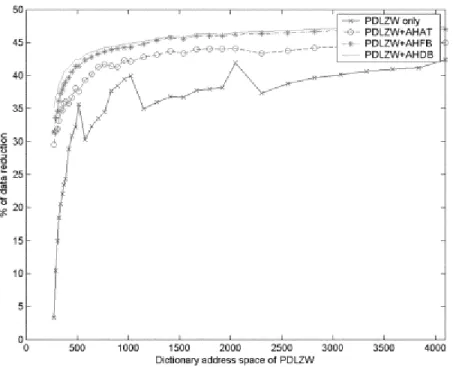
Fig 4.3 Percentage of data reduction of various compression schemes………....36
Fig 4.4 Number of bytes required in various compression schemes……….…37
Fig 5.1 Illustrating Example of AHDB algorithm……….42
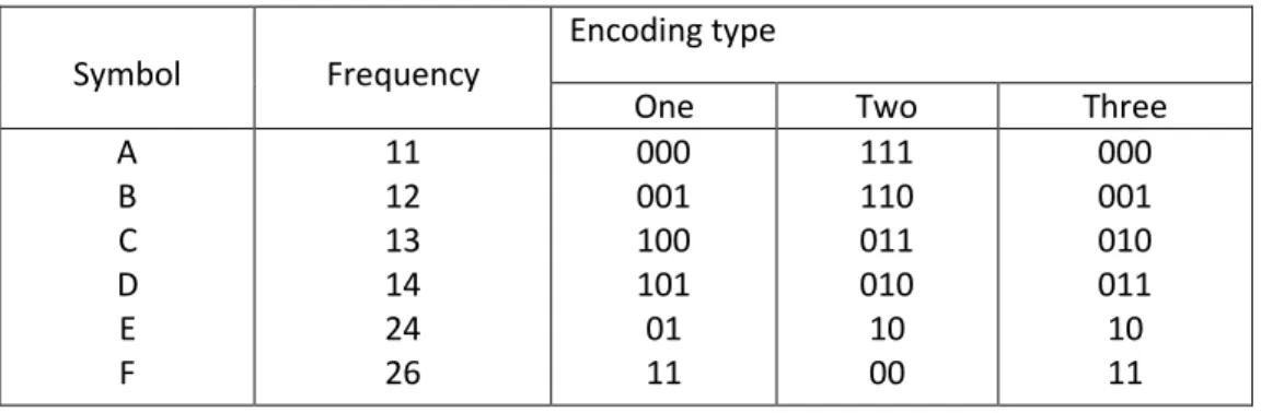
Fig 5.2 Example of the Huffman tree and its three possible encodings……….46
Fig 5.3 Two Stage Architecture for compression………..………53
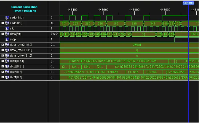
Fig 6.1 PDLZW output………..…..….55
Fig 6.2 Write operation in Four dictionaries……….…55
Fig 6.3 Dic-1 contents………...56
Fig 6.4 Dic-2 Contents………..56
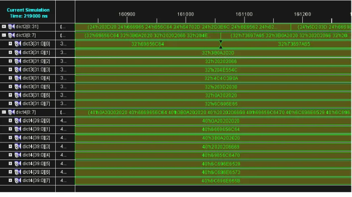
Fig 6.5 Dic-3, 4 Contents………...57
Fig 6.6 AHDB processor Output………...57
Fig 6.7 Order list of AHDB………...58
Fig 6.8 PDLZW+AHDB algorithm………...58
iii
List of Tables
Table No. Table Title Page No.
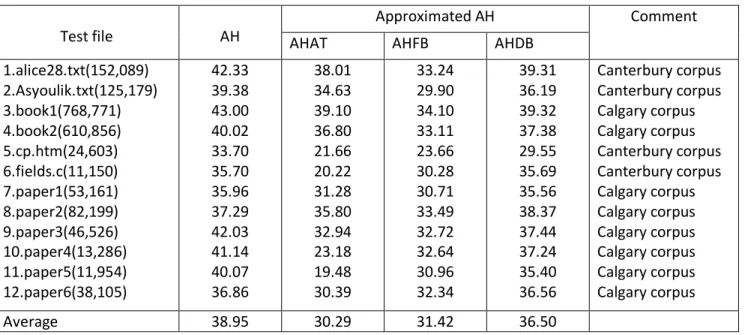
Table 2.1 Step-by-step details for an LZW example ………..9 Table 4.1 Ten Possible Partitions of the 368-Address Dictionary Set………38 Table 5.1 Performance Comparisons between AH Algorithm and It‟s……….44 Various Approximated Versions In The Case Of Text Files
Table 5.2 Performance Comparisons Between AH Algorithm and It‟s ………...44 Various Approximated Versions In The Case Of Executable Files
Table 5.3 Overall Performance Comparisons Between the AH Algorithm……….…45 And It‟s Various Approximated Versions.
Table 5.4 Canonical Huffman Code Used In the AHDB Processor………...47 Table 5.5 Performance Comparison of Data Reduction between ……….…51 COMPRESS, PDLZW + AH, PDLZW + AHAT, PDLZW + AHFB,
AND PDLZW + AHDB for Text files
Table 5.6 Performance Comparison of Data Reduction between ………...…51 COMPRESS, PDLZW + AH, PDLZW + AHAT, PDLZW + AHFB,
iv
Abbreviations Used
LZW Algorithm Lempel Ziv Welch algorithm AH Algorithm Adaptive Huffman Algorithm PDLZW algorithm Parellel Dictionary LZW Algorithm FGK algorithm Failer, Gallager, and Knuth Algorithm
AHAT Adaptive Huffman algorithm with transposition
AHFB Adaptive Huffman algorithm with fixed-block exchange AHDB Adaptive Huffman algorithm with dynamic-block exchange
Chapter
1
INTRODUCTION
2
DATA compression is a method of encoding rules that allows substantial reduction in the total number of bits to store or transmit a file. Currently, two basic classes of data compression are applied in different areas. One of these is lossy data compression, which is widely used to compress image data files for communication or archives purposes. The other is lossless data compression that is commonly used to transmit or archive text or binary files required to keep their information intact at any time.
1.1 Motivation
Data transmission and storage cost money. The more information being dealt with, the more it costs. In spite of this, most digital data are not stored in the most compact form. Rather, they are stored in whatever way makes them easiest to use, such as: ASCII text from word processors, binary code that can be executed on a computer, individual samples from a data acquisition system, etc. Typically, these easy-to-use encoding methods require data files about twice as large as actually needed to represent the information. Data compression is the general term for the various algorithms and programs developed to address this problem. A compression program is used to convert data from an easy-to-use format to one optimized for compactness. Likewise, an
uncompression program returns the information to its original form.
A new two-stage hardware architecture is proposed that combines the features of both parallel dictionary LZW (PDLZW) and an approximated adaptive Huffman (AH) algorithms. In the proposed architecture, an ordered list instead of the tree based structure is used in the AH algorithm for speeding up the compression data rate. The resulting architecture shows that it outperforms the AH algorithm at the cost of only one-fourth the hardware resource, is only about 7% inferior to UNIX compress on the average cases, and outperforms the compress utility in some cases. The compress utility is an implementation of LZW algorithm.
3
1.2 THESIS OUTLINE:
Following the introduction, the remaining part of the thesis is organized as under Chapter 2 discusses LZW algorithm for compression and decompression.
Chapter 3 discusses the Adaptive Huffman algorithm by FGK and modified algorithm By JEFFREY SCOTT VITTER.
Chapter 4 discusses the Parallel dictionary LZW algorithm and its architecture. Chapter 5 discusses The Two Stage proposed Architecture and its Implementation Chapter 6 discusses the simulation results
Chapter
2
5
LZW compression is named after its developers, A. Lempel and J. Ziv, with later modifications by Terry A. Welch. It is the foremost technique for general purpose data compression due to its simplicity and versatility. Typically, we can expect LZW to compress text, executable code, and similar data files to about one-half their original size. LZW also performs well when presented with extremely redundant data files, such as tabulated numbers, computer source code, and acquired signals.
2.1 LZW Compression
LZW compression uses a code table, as illustrated in Fig. 2.1. A common choice is to provide 4096 entries in the table. In this case, the LZW encoded data consists entirely of 12 bit codes, each referring to one of the entries in the code table. Decompression is achieved by taking each code from the compressed file, and translating it through the code table to find what character or characters it represents. Codes 0-255 in the code table are always assigned to represent single bytes from the input file. For example, if only these first 256 codes were used, each byte in the original file would be converted into 12 bits in the LZW encoded file, resulting in a 50% larger file size. During uncompression, each 12 bit code would be translated via the code table back into the single bytes. But, this wouldn't be a useful situation.
code number translation
0000 0 0001 1
: : : : 0254 254 0255 255 0256 145 201 4 0257 243 245 : : 4095 xxx xxx xxx Id en ti cal c o d e Uni q u e cod e
LZW Algorithm
6
FIGURE 2.1 Example of code table compression. This is the basis of the popular LZW
compression method. Encoding occurs by identifying sequences of bytes in the original file that exist in the code table. The 12 bit code representing the sequence is placed in the compressed file instead of the sequence. The first 256 entries in the table correspond to the single byte values, 0 to 255, while the remaining entries correspond to sequences of bytes. The LZW algorithm is an efficient way of generating the code table based on the particular data being compressed. (The code table in this figure is a simplified example, not one actually generated by the LZW algorithm).
original data stream: 123 145 201 4 119 89 243 245 59 11 206 145 201 4 243 245 . . . . .
code table encoded: 123 256 119 89 257 59 11 206 256 257 . . . .
The LZW method achieves compression by using codes 256 through 4095 to represent
sequences of bytes. For example, code 523 may represent the sequence of three bytes: 231 124 234. Each time the compression algorithm encounters this sequence in the input file, code 523 is placed in the encoded file. During decompression, code 523 is translated via the code table to recreate the true 3 byte sequence. The longer the sequence assigned to a single code, and the more often the sequence is repeated, the higher the compression achieved.
Although this is a simple approach, there are two major obstacles that need to be overcome: (1) How to determine what sequences should be in the code table, and
(2) How to provide the decompression program the same code table used by the compression program. The LZW algorithm exquisitely solves both these problems.
7
When the LZW program starts to encode a file, the code table contains only the first 256 entries, with the remainder of the table being blank. This means that the first codes going into the compressed file are simply the single bytes from the input file being converted to 12 bits. As the encoding continues, the LZW algorithm identifies repeated sequences in the data, and adds them to the code table. Compression starts the second time a sequence is encountered. The key point is that a sequence from the input file is not added to the code table until it has already been placed in the compressed file as individual characters (codes 0 to 255). This is important because it allows the decompression program to reconstruct the code table directly from the compressed data, without having to transmit the code table separately.
2.1.1 LZW compression algorithm
1 Initialize table with single character strings 2 String = first input character
3 WHILE not end of input stream 4 Char = next input character
5 IF String + Char is in the string table 6 String = String + Char
7 ELSE
8 output the code for String
9 add String + Char to the string table 10 String = Char
11 END WHILE 12 output code for String
The variable, CHAR, is a single byte. The variable, STRING, is a variable length sequence of bytes. Data are read from the input file (Step 2 & 4) as single bytes, and written to the compressed file (Step 8) as 12 bit codes. Table 2.1 shows an example of this algorithm.
LZW Algorithm
8 CHAR STRING
+ CHAR
In Table ? Output Add to Table
New STRING
Comments
1 t t t First character-no action
2 h th No t 256=th h 3 e he No h 257=he e 4 / e/ No e 258=e/ / 5 r /r No / 259=/r r 6 a ra No r 260=ra a 7 i ai No a 261=ai i 8 n in No i 262=in n 9 / n/ No n 263=n/ / 10 i /i No / 264=/i i
11 n in yes(262) in First match found
12 / in/ No 262 265=in/ /
13 S /S No / 266=/S S
14 p Sp No S 267=Sp p
15 a pa No p 268=pa a
16 i ai Yes(261) ai Matches ai , ain not in table yet 17 n ain No 261 269=ain n ain added to table
18 / n/ Yes(263) n/ 19 f n/f No 263 270=n/f f 20 a fa No f 271=fa a 21 l al No a 272=al l 22 l ll No l 273=ll l 23 s ls No l 274=ls s 24 / s/ No s 275=s/ / 25 m /m No / 276=/m m 26 a ma No m 277=ma a 27 i ai Yes(261) ai Matches ai
28 n ain Yes(269) ain Matches longer string , ain
29 l ainl No 269 278=ainl l
30 y ly No l 279=ly y
9
32 o /o No / 281=/o o
33 n on No o 282=on n
34 / n/ Yes(263) n/
35 t n/t No 263 283=n/t t
36 h th Yes(256) th Matches th , the not in the table
yet
37 e the No 256 284=the e the added to table
38 / e/ yes e/
39 p e/p No 258 285=e/p p
40 l pl No p 286=pl l
41 a la No l 287=la a
42 i ai Yes(261) ai Matches ai
43 n ain Yes(269) ain Matches longer string ain
44 / ain/ No 269 288=ain/ /
45 EOF / / End of file , output STRING
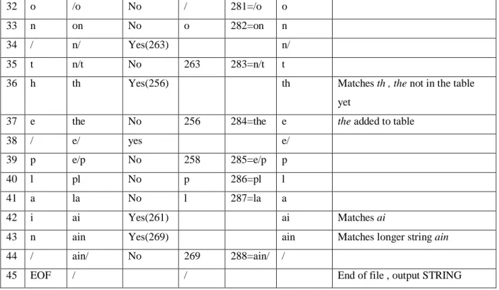
Table 2.1 provides the step-by-step details for an example input file consisting of 45 bytes, the
ASCII text string: the/rain/in/Spain/falls/mainly/on/the/plain. When we say that the LZW algorithm reads the character "a" from the input file, we mean it reads the value: 01100001 (97 expressed in 8 bits), where 97 is "a" in ASCII. When we say it writes the character "a" to the encoded file, we mean it writes: 000001100001 (97 expressed in 12 bits).
The compression algorithm uses two variables: CHAR and STRING. The variable, CHAR, holds a single character, i.e., a single byte value between 0 and 255. The variable, STRING, is a variable length string, i.e., a group of one or more characters, with each character being a single byte. In box 1 of Fig. 2.1, the program starts by taking the first byte from the input file, and placing it in the variable, STRING. Table 2.1 shows this action in line 1. This is followed by the algorithm looping for each additional byte in the input file, controlled in the flow diagram by Step 3. Each time a byte is read from the input file (Step 4), it is stored in the variable, CHAR. The data table is then searched to determine if the concatenation of the two variables,
LZW Algorithm
10
If a match in the code table is not found, three actions are taken, as shown in Step 8, 9 & 10. In Step 8, the 12 bit code corresponding to the contents of the variable, STRING, is written to the compressed file. In Step 9, a new code is created in the table for the concatenation of
STRING+CHAR. In Step 10, the variable, STRING, takes the value of the variable, CHAR. An example of these actions is shown in lines 2 through 10 in Table 2.1, for the first 10 bytes of the example file.
When a match in the code table isfound (Step 5), the concatenation of STRING+CHAR is stored in the variable, STRING, without any other action taking place (Step 6). That is, if a matching sequence is found in the table, no action should be taken before determining if there is a longer
matching sequence also in the table. An example of this is shown in line 11, where the sequence:
STRING+CHAR = in, is identified as already having a code in the table. In line 12, the next character from the input file, /, is added to the sequence, and the code table is searched for: in/. Since this longer sequence is not in the table, the program adds it to the table, outputs the code for the shorter sequence that is in the table (code 262), and starts over searching for sequences beginning with the character, „/‟. This flow of events is continued until there are no more characters in the input file. The program is wrapped up with the code corresponding to the current value of STRING being written to the compressed file (as illustrated in Step 8 of Fig. Table 2.1 and line 45 of Table 2.1).
2.2 LZW Decompression
The LZW decompression algorithm is given below. Each code is read from the compressed file and compared to the code table to provide the translation. As each code is processed in this manner, the code table is updated so that it continually matches the one used during the compression. However, there is a small complication in the decompression routine. There are certain combinations of data that result in the decompression algorithm receiving a code that does not yet exist in its code table. This contingency is handled in boxes 6, 7 & 8.
11
2.2.1 LZW Decompression algorithm
1 Initialize table with single character strings 2 OLD = first input code
3 output translation of OLD 4 WHILE not end of input stream 5 NEW = next input code
6 IF NEW is not in the string table 7 S = translation of OLD 8 S = S + C 9 ELSE 10 S = translation of NEW 11 output S 12 C = first character of S 13 OLD + C to the string table 14 OLD = NEW
15 END WHILE
Only a few dozen lines of code are required for the most elementary LZW programs. The real difficulty lies in the efficient management of the code table. The brute force approach results in large memory requirements and a slow program execution. Several tricks are used in commercial LZW programs to improve their performance. For instance, the memory problem arises because it is not know beforehand how long each of the character strings for each code will be. Most LZW programs can be handled by taking advantage of the redundant nature of the code table. For example, look at line 29 in Table 2.2, where code 278 is defined to be ainl. Rather than storing these four bytes, code 278 could be stored as: code 269 + l, where code 269 was previously defined as ain in line 17. Likewise, code 269 would be stored as: code 261 + n, where code 261 was previously defined as ai in line 7. This pattern always holds: every code can be expressed as a previous code plus one new character. This Algorithm is Coded in C language.
Chapter
3
Adaptive Huffman
13
3.1. Introduction
A new one-pass algorithm for constructing dynamic Huffman codes is introduced and analyzed. We also analyze the one-pass algorithm due to Failer, Gallager, and Knuth. In each algorithm, both the sender and the receiver maintain equivalent dynamically varying Huffman trees, and the coding is done in real time. We show that the number of bits used by the new algorithm to encode a message containing l letters is < l bits more than that used by the conventional two-pass Huffman scheme, independent of the alphabet size. The new algorithm is well suited for online encoding/decoding in data networks and for file compression.
Variable-length source codes, such as those constructed by the well-known two pass algorithm due to D.A.Huffman [5], are becoming increasingly important for several reasons. Communication costs in distributed systems are beginning to dominate the costs for internal computation and storage. Variable-length codes often use fewer bits per source letter than do fixed-length codes such as ASCII and EBCDIC, which require │log n│ bits per letter, where n, is the alphabet size. This can yield tremendous savings in packet-based communication systems. Moreover, the buffering needed to support variable-length coding is becoming an inherent part of many systems.
The binary tree produced by Huffman‟s algorithm minimizes the weighted external path length ∑j wj lj among all binary trees, where wj is the weight of the j th leaf, and l j is its depth in the
tree. Let us suppose there are k distinct letters a1, a2. . . ak in a message to be encoded, and let us
consider a Huffman tree with k leaves in which wj for 1 ≤ j ≤ k , is the number of occurrences of
aj in the message. One way to encode the message is to assign a static code to each of the k
distinct letters, and to replace each letter in the message by its corresponding code. Huffman‟s algorithm uses an optimum static code, in which each occurrence of aj for 1 ≤ j ≤ k, is encoded
by the lj bits specifying the path in the Huffman tree from the root to the jth leaf, where “0”
means “to the left” and “1” means “to the right”.
One disadvantage of Huffman‟s method is that it makes two passes over the data: one pass to collect frequency counts of the letters in the message, followed by the construction of a Huffman tree and transmission of the tree to the receiver; and a second pass to encode and transmit the
Adaptive Huffman Algorithm
14
letters themselves, based on the static tree structure. This causes delay when used for network communication, and in file compression applications the extra disk accesses can slow down the algorithm.
Faller and Gallager independently proposed a one-pass scheme, later improved substantially by Knuth, for constructing dynamic Huffman codes. The binary tree that the sender uses to encode the (t + 1) st letter in the message (and that the receiver uses to reconstruct the (t + 1)st letter is a Huffman tree for the first t letters of the message. Both sender and receiver start with the same initial tree and thereafter stay synchronized; they use the same algorithm to modify the tree after each letter is processed. Thus there is never need for the sender to transmit the tree to the receiver, unlike the case of the two-pass method. The processing time required to encode and decode a letter is proportional to the length of the letter‟s encoding, so the processing can be done in real time.
Of course, one-pass methods are not very interesting if the number of bits transmitted is significantly greater than with Huffman‟s two-pass method. This paper gives the first analytical study of the efficiency of dynamic Huffman codes. We derive a precise and clean characterization of the difference in length between the encoded message produced by a dynamic Huffman code and the encoding of the same message produced by a static Huffman code. The length (in bits) of the encoding produced by the algorithm of Faller, Gallager, and Knuth (Algorithm FGK) is shown to be at most ≈ 2 S + t, where S is the length of the encoding by a static Huffman code, and t is the number of letters in the original message. More important, the insights we gain from the analysis lead us to develop a new one pass scheme, which we call Algorithm A, that produces encodings of < S + t bits. That is, compared with the two-pass method, Algorithm A uses less than one extra bit per letter. We prove this is optimum in the worst case among all one-pass Huffman schemes.
It is impossible to show that a given dynamic code is optimum among all dynamic codes, because one can easily imagine non-Huffman-like codes that are optimized for specific messages. Thus there can be no global optimum. For that reason we restrict our model of one-pass schemes to the important class of one one-pass Huffman schemes, in which the next letter of the message is encoded on the basis of a Huffman tree for the previous letters. We also do not
15
consider the worst case encoding length, among all possible messages of the same length, because for any one-pass scheme and any alphabet size n we can construct a message that is encoded with an average of ≥ │ log2 n│ bits per letter. The harder and more important
measure, which we address in this paper, is the worst-case difference in length between the dynamic and static encodings of the same message.
One intuition why the dynamic code produced by Algorithm A is optimum in our model is that the tree it uses to process the (t + 1) st letter is not only a Huffman tree with respect to the first t letters (that is, ∑j wj lj is minimized), but it also minimizes the external path length ∑j lj and the
height maxj {lj} among all Huffman trees. This helps guard against a lengthy encoding for the
(t + 1) st letter. Our implementation is based on an efficient data structure we call a floating tree. Algorithm A is well suited for practical use and has several applications. Algorithm FGK is already used for tile compression in the compact command available under the 4.2BSD UNIX‟ operating system. Most Huffman-like algorithms use roughly the same number of bits to encode a message when the message is long; the main distinguishing feature is the coding efficiency for short messages, where overhead is more apparent. Empirical tests show that Algorithm Λ uses fewer bits for short messages than do Huffman‟s algorithm and Algorithm FGK. Algorithm Λ can thus be used as a general-purpose coding scheme for network communication and as an efficient subroutine in word-based compaction algorithms.
In the next section we review the basic concepts of Huffman‟s two-pass algorithm and the one-pass Algorithm FGK. In Section 3 we develop the main techniques for our analysis and apply them to Algorithm FGK. In Section 4 we introduce Algorithm Λ and prove that it runs in real time and gives optimal encodings, in terms of our model defined above. In Section 5 we describe several experiments comparing dynamic and static codes. Our conclusions are listed in Section 6.
3.2. Huffman’s Algorithm and FGK Algorithm
In this section we discuss Huffman‟s original algorithm and the one-pass Algorithm FGK. First let us define the notation we use
Adaptive Huffman Algorithm
16
Definition 2.1. We define n = alphabet size;
aj = jth letter in the alphabet;
t = number of letters in the message processed so far; at = ai1,, ai2,, . . . , ait, the first t letters of the message;
k = number of distinct letters processed so far; wj = number of occurrences of aj processed so, far;
lj = distance from the root of the Huffman tree to aj‟s leaf.
The constraints are 1 ≤ j, k ≤ n, and 0 ≤ wj ≤ t.
In many applications, the final value oft is much greater than n. For example, a book written in English on a conventional typewriter might correspond to t ≈ 106 and n = 87. The ASCII alphabet size is n = 128.
Huffman‟s two-pass algorithm operates by first computing the letter frequencies wj in the entire
message. A leaf node is created for each letter aj that occurs in the message; the weight of aj‟s
leaf is its frequency wj. The meat of the algorithm is the following procedure for processing the
leaves and constructing a binary tree of minimum weighted external path length ∑j wj lj
Store the k leaves in a list L;
While L contains at least two nodes do begin
Remove from L two nodes x and y of smallest weight; Create a new node p, and make p the parent of x and y; p‟s weight := x‟s weight + y‟s weight;
Insert p into L end;
The node remaining in L at the end of the algorithm is the root of the desired binary tree. We call a tree that can be constructed in this way a “Huffman tree.” It is easy to show by contradiction
17
that its weighted external path length is minimum among all possible binary trees for the given leaves. In each iteration of the while loop, there may be a choice of which two nodes of minimum weight to remove from L. Different choices may produce structurally different Huffman trees, but all possible Huffman trees will have the same weighted external path length. In the second pass of Huffman‟s algorithm, the message is encoded using the Huffman tree constructed in pass 1. The first thing the sender transmits to the receiver is the shape of the Huffman tree and the correspondence between the leaves and the letters of the alphabet. This is followed by the encodings of the individual letters in the message. Each occurrence of aj is
encoded by the sequence of 0‟s and 1‟s that specifies the path from the root of the tree to aj‟s
leaf, using the convention that “0” means “to the left” and “1” means “to the right.”
To retrieve the original message, the receiver first reconstructs the Huffman tree on the basis of the shape and leaf information. Then the receiver navigates through the tree by starting at the root and following the path specified by the 0 and 1 bits until a leaf is reached. The letter corresponding to that leaf is output, and the navigation begins again at the root.
Codes like this, which correspond in a natural way to a binary tree, are called prefix codes, since the code for one letter cannot be a proper prefix of the code for another letter. The number of bits transmitted is equal to the weighted external path length ∑j wj lj plus the number of bits needed
to encode the shape of the tree and the labeling of the leaves. Huffman‟s algorithm produces a prefix code of minimum length, since ∑j wj lj is minimized.
The two main disadvantages of Huffman‟s algorithm are its two-pass nature and the overhead required to transmit the shape of the tree. In section we explore alternative one-pass methods, in which letters are encoded “on the fly.” We do not use a static code based on a single binary tree, since we are not allowed an initial pass to determine the letter frequencies necessary for computing an optimal tree. Instead the coding is based on a dynamically varying Huffman tree. That is, the tree used to process the (t + 1)st letter is a Huffman tree with respect to µt . The
sender encodes the (t + 1)st letter ait, in the message by the sequence of 0‟s and 1‟s that specifies
the path from the root to ait„s leaf. The receiver then recovers the original letter by the
corresponding traversal of its copy of the tree. Both sender and receiver then modify their copies of the tree before the next letter is processed so that it becomes a Huffman tree for µt+ 1. A key
Adaptive Huffman Algorithm
18
point is that neither the tree nor its modification needs to be transmitted, because the sender and receiver use the same modification algorithm and thus always have equivalent copies of the tree.
(a)
(b) 32 21 11 5 10 2 3 5 5 6 11 11 1 2 3 4 5 7 6 8 9 10 a b c d e f 3 2 2 1 1 0 1 1 5 1 1 5 5 6 2 3 a b d e c 7 8 f 3 1 2 5 6 1 0 9 1 1 4
19
(c)
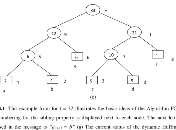
FIG. 3.1. This example from for t = 32 illustrates the basic ideas of the Algorithm FGK. The
node numbering for the sibling property is displayed next to each node. The next letter to be processed in the message is “ai t+1 = b” (a) The current status of the dynamic Huffman tree,
which is a Huffman tree for µt , the first t letters in the message. The encoding for “b” is “1011”,
given by the path from the root to the leaf for “b”. (b) The tree resulting from the interchange process. It is a Huffman tree for µt and has the property that the weights of the traversed nodes
can be incremented by I without violating the sibling property. (c) The final tree, which is the tree in (b) with the incrementing done, is a Huffman tree for µt+1.
Another key concept behind dynamic Huffman codes is the following elegant so-called characterization of Huffman trees:
Sibling Property: A binary tree with p leaves of nonnegative weight is a Huffman tree if and only if
(1) the p leaves have nonnegative weights w1, . . . , wp, and the weight of each internal node is the
sum of the weights of its children; and
33 12 21 6 6 2 4 10 1 1 5 5 1 2 3 4 5 6 7 8 9 1 0 1 1 a b c d e f
Adaptive Huffman Algorithm
20
(2) the nodes can be numbered in nondecreasing order by weight, so that nodes 2j - 1 and 2j are siblings, for 1≤ j ≤ p - 1, and their common parent node is higher in the numbering.
The node numbering corresponds to the order in which the nodes are combined by Huffman‟s algorithm: Nodes 1 and 2 are combined first, nodes 3 and 4 are combined second, nodes 5 and 6 are combined next, and so on.
Suppose that, µt = ai,, ai2, . . . , ait, has already been processed .The next letter ait+1, is encoded
and decoded using a Huffman tree for µt. The main difficulty is how to modify this tree quickly
in order to get a Huffman tree for µt+1 . Let us consider the example in Figure 1, for the case
t = 32, ait+1 = “b”. It is not good enough to simply increment by 1 the weights of ait+1,„s leaf and
its ancestors, because the resulting tree will not be a Huffman tree, as it will violate the sibling property.
(a)
(b)
FIG.3.2. Algorithm FGK operating on the message “abcd ….. “. (a) The Huffman tree
immediately before the fourth letter “d” is processed. The encoding for “d” is specified by the path to the 0-node, namely, “100”. (b) After Update is called.
The nodes will no longer be numbered in non decreasing order by weight; node 4 will have weight 6, but node 5 will still have weight 5. Such a tree could therefore not be constructed via Huffman‟s two-pass algorithm.
3 1 1 0 1 1 3 4 5 6 7 8 9 1 2 2 4 0 1 1 1 1 2 1 2 3 4 5 6 7 8 9 a b c a b
21
The solution can most easily be described as a two-phase process (although for implementation purposes both phases can be combined easily into one). In the first phase, we transform the tree into another Huffman tree for µt, to which the simple incrementing process described above can
be applied successfully in phase 2 to get a Huffman tree for µt+1. The first phase begins with the
leaf of ait+1 as the current node. We repeatedly interchange the contents of the current node,
including the sub tree rooted there, with that of the highest numbered node of the same weight, and make the parent of the latter node the new current node. The current node in Figure la is initially node 2. No interchange is possible, so its parent (node 4) becomes the new current node. The contents of nodes 4 and 5 are then interchanged, and node 8 becomes the new current node. Finally, the contents of nodes 8 and 9 are interchanged, and node 11 becomes the new current node. The first phase halts when the root is reached. The resulting tree is pictured in Figure lb. It is easy to verify that it is a Huffman tree for µt (i.e., it satisfies the sibling property), since each
interchange operates on nodes of the same weight. In the second phase, we turn this tree into the desired Huffman tree for µt+1by incrementing the weights of ait+1’sleaf and its ancestors by 1.
Figure 3.1(c) depicts the final tree, in which the incrementing is done.
The reason why the final tree is a Huffman tree for µt+1 can be explained in terms of the sibling
property: The numbering of the nodes is the same after the incrementing as before. Condition 1 and the second part of condition 2 of the sibling property are trivially preserved by the incrementing. We can thus restrict our attention to the nodes that are incremented. Before each such node is incremented, it is the largest numbered node of its weight. Hence, its weight can be increased by 1 without becoming larger than that of the next node in the numbering, thus preserving the sibling property.
When k < n, we use a single 0-node to represent the n - k unused letters in the alphabet. When the (t + 1) st letter in the message is processed, if it does not appear in µt the 0-node is split to
create a leaf node for it, as illustrated in Figure 2. The (t + 1) st letter is encoded by the path in the tree from the root to the 0-node, followed by some extra bits that specify which of the n - k unused letters it is, using a simple prefix code.
Adaptive Huffman Algorithm
22
Phases 1 and 2 can be combined in a single traversal from the leaf of ait+1, to the root, as shown
below. Each iteration of the while loop runs in constant time, with the appropriate data structure, so that the processing time is proportional to the encoding length.
Procedure Update; begin
q:= leaf node corresponding to ait+1 ;
if (q is the 0-node) and (k < n - 1) then begin
Replace q by a parent 0-node with two leaf 0-node children, numbered in the order left child, right child, parent;
q:= right child just created end;
if q is the sibling of a 0-node then begin
Interchange q with the highest numbered leaf of the same weight; Increment q‟s weight by 1;
q := parent of q end ;
while q is not the root of the Huffman tree do begin { Main loop }
Interchange q with the highest numbered node of the same weight: { q is now the highest numbered node of its weight }
Increment q‟s weight by 1; q := parent of q
end end;
We denote an interchange in which q moves up one level by ↑ and an interchange between q and another node on the same level by →.For example, in Figure 1, the\ interchange of nodes 8 and 9 is of type ↑,whereas that of nodes 4 and 5 is of type →. Oddly enough, it is also possible for q to
23
move down a level during an interchange, as illustrated in Figure 3; we denote such an interchange by ↓.
No two nodes with the same weight can be more than one level apart in the tree, except if one is the sibling of the 0-node. This follows by contradiction, since otherwise it will be possible to interchange nodes and get a binary tree having smaller external weighted path length. Figure 4 shows the result of what would happen if the letter “c” (rather than “d”) were the next letter processed using the tree in Figure 2a. The first interchange involves nodes two levels apart; the node moving up is the sibling of the 0-node. We shall designate this type of two-level interchange by ↑↑. There can be at most one ↑↑ for each call to Update.
3.3. Optimum Dynamic Huffman Codes
This section describe Algorithm Λ and show that it runs in real time and is optimum in our model of one-pass Huffman algorithms. There were two motivating factors in its design:
(1) The number of ↑‟s should be bounded by some small number (in our case, 1) during each call to Update.
(2) The dynamic Huffman tree should be constructed to minimize not only ∑jWjlj, but also & 4
and maxi(h), which intuitively has the effect of preventing a lengthy encoding of the next letter in the message
3.3.1 IMPLICIT NUMBERING
One of the key ideas of Algorithm A is the use of a numbering scheme for the nodes that is different from the one used by Algorithm FGK. We use an implicit numbering, in which the node numbering corresponds to the visual representation of the tree. That is, the nodes of the tree are numbered in increasing order by level; nodes on one level are numbered lower than the nodes on the next higher level. Nodes on the same level are numbered in increasing order from left to right.
Adaptive Huffman Algorithm
24
3.3.2 DATA STRUCTURE
In this section we summarize the main features of our data structure for Algorithm Λ. The details and implementation appears in [9]. The main operations that the data structure must support are as follows:
-It must represent a binary Huffman tree with nonnegative weights that maintains invariant (*). -It must store a contiguous list of internal tree nodes in non decreasing order by weight; internal nodes of the same weight are ordered with respect to the implicit numbering. A similar list is stored for the leaves.
-It must find the leader of a node‟s block, for any given node, on the basis of the implicit numbering.
-It must interchange the contents of two leaves of the same weight.
-It must increment the weight of the leader of a block by 1, which can cause the node‟s implicit numbering to “slide” past the numberings of the nodes in the next block, causing their numberings to each decrease by 1.
-It must represent the correspondence between the k letters of the alphabet that have appeared in the message and the positive-weight leaves in the tree.
-It must represent the n-k letters in the alphabet that have not yet appeared in the message by a single leaf 0-node in the Huffman tree.
The data structure makes use of an explicit numbering, which corresponds to the physical storage locations used to store information about the nodes. This is not to be confused with the implicit numbering defined in the last section. Leaf nodes are explicitly numbered n, n - 1, n - 2, . . . in contiguous locations, and internal nodes are explicitly numbered 2n - 1, 2n - 2, 2n - 3 . . . contiguously; node q is a leaf if q ≤ n.
There is a close relationship between the explicit and implicit numberings, as specified in the second operation listed above: For two internal nodes p and q, we have p < q in the explicit numbering if p < q in the implicit numbering; the same holds for two leaves p and q.
The tree data structure is called a floating tree because the parent and child pointers for the nodes are not maintained explicitly. Instead, each block has a parent pointer and a right-child pointer
25
that point to the parent and right child of the leader of the block. Because of the contiguous storage of leaves and of internal nodes, the locations of the parents and children of the other nodes in the block can be computed in constant time via an offset calculation from the block‟s
parent and right-child pointer. This allows a node to slide over an entire block without having to update more than a constant number of pointers. Each execution of Slide- and Increment thus takes constant time, so the encoding and decoding in Algorithm Λ can be done in real time. The total amount of storage needed for the data structure is roughly 16n log n + 15n + 2n log t bits, which is about 4n log n bits more than used by the implementation of Algorithm FGK . The storage can be reduced slightly by extra programming. If storage is dynamically allocated, as opposed to preallocated via arrays, it will typically be much less. The running time is comparable to that of Algorithm FGK.
One nice feature of a floating tree, due to the use of implicit numbering, is that the parent of nodes 2j - 1 and 2j is less than the parent of nodes 2j + 1 and 2j + 2 in both the implicit and explicit numberings.
Chapter
4
27
4.1 Introduction
The major feature of conventional implementations of the LZW data compression algorithms is that they usually use only one fixed-word-width dictionary. Hence, a quite lot of compression time is wasted in searching the large-address-space dictionary instead of using a unique fixed-word-width dictionary a hierarchical variable-fixed-word-width dictionary set containing several small address space dictionaries with increasing word widths is used for the compression algorithm. The results show that the new architecture not only can be easily implemented in VLSI technology due to its high regularity but also has faster compression rate since it no longer needs to search the dictionary recursively as the conventional implementations do.
Lossless data compression algorithms include mainly LZ codes [5, 6]. A most popular version of LZ algorithm is called LZW algorithm [4]. However, it requires quite a lot of time to adjust the dictionary. To improve this, two alternative versions of LZW were proposed. These are DLZW (dynamic LZW) and WDLZW (word-based DLZW) [5]. Both improve LZW algorithm in the following ways. First, it initializes the dictionary with different combinations of characters instead of single character of the underlying character set. Second, it uses a hierarchy of dictionaries with successively increasing word widths. Third, each entry associates a frequency counter. That is, it implements LRU policy. It was shown that both algorithms outperform LZW
[4]. However, it also complicates the hardware control logic.
In order to reduce the hardware cost, a simplified DLZW architecture suited for VLSI realization called PDLZW (parallel dictionary LZW) architecture. This architecture improves and modifies the features of both LZW and DLZW algorithms in the following ways. First, instead of initializing the dictionary with single character or different combinations of characters a virtual dictionary with the initial │∑│ address space is reserved. This dictionary only takes up a part of address space but costs no hardware. Second, a hierarchical parallel dictionary set with successively increasing word widths is used. Third, the simplest dictionary update policy called FIFO (first-in first-out) is used to simplify the hardware implementation. The resulting
Two Stage Architecture PDLZW Algorithm
28
architecture shows that it outperforms Huffman algorithm in all cases and about only 5% below UNIX compress on the average case but in some cases outperforms the compress utility.
4.2. Dictionary Design Considerations
The dictionary used in PDLZW compression algorithm is one that consists of m small variable-word width dictionaries, numbered from 0 to m - 1, with each of which increases its word width by one byte. That is to say, dictionary 0 has one byte word width, dictionary 1 two bytes, and so on. These dictionaries: constitute a dictionary set. In general, different address space distributions of the dictionary set will present significantly distinct performance of the PDLZW compression algorithm. However, the optimal distribution is strongly dependent on the actual input data files. Different data, profiles have their own optimal address space distributions. Therefore, in order to find a more general distribution, several different kinds of data samples are: run with various partitions of a given address space. Each partition corresponds to a dictionary set. For instance, the 1K address space is partitioned into ten different combinations and hence ten dictionary sets.
An important consideration for hardware implementation is the required dictionary address space that dominates the chip cost for achieving an acceptable compression ratio.
4.3. Compression processor architecture
In the conventional dictionary implementations of LZW algorithm, they use a unique and large address space dictionary so that the search time of the dictionary is quite long even with CAM (content addressable memory). In our design the unique dictionary is replaced with a dictionary set consisting of several smaller dictionaries with different address spaces and word widths. As doing so the dictionary set not only has small lookup time but also can operate in parallel.
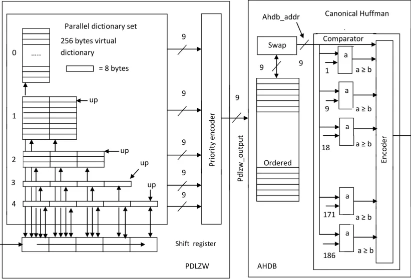
The architecture of PDLZW compression processor is depicted in Figure 4.1. It consists of CAMs, an 5- byte shift register, a shift and update control, and a codeword output circuit. The word widths of CAMs increase gradually from 2 bytes up to 5 bytes with 5 different address spaces: 256, 64, 32, 8 and 8 words. The input string is shifted into the 5-byte shift register. The shift operation can be implemented by barrel shifter for achieving a faster speed. Thus there are 5 bytes can be searched from all CAMs simultaneously. In general, it is possible that there are
29
several dictionaries in the dictionary set matched with the incoming string at the same time with different string lengths. The matched address within a dictionary along with the dictionary number of the dictionary that has largest number of bytes matched is outputted as the output codeword, which is detected and combined by the priority encoder. The maximum length string matched along with the next character is then written into the next entry pointed by the update pointer (UP) of the next dictionary (CAM) enabled by the shift and dictionary update control circuit. Each dictionary has its own UP that always points to the word to be inserted next. Each update pointer counts from 0 up to its maximum value and then back to 0. Hence, the FIFO update policy is realized. The update operation is inhibited if the next dictionary number is greater than or equal to the maximum dictionary number.
Fig 4.1 PDLZW Architecture for compression
….. P ri o ri ty enc o d er up up up up 0 1 2 3 4 = 8 bytes bytes 256 bytes virtual dictionary
Parallel dictionary set
PDLZW
Two Stage Architecture PDLZW Algorithm
30
The data rate for the PDLZW compression processor is at least one byte per memory cycle. The memory cycle is mainly determined by the cycle time of CAMs but it is quite small since the maximum capacity of CAMs is only 256 words. Therefore, a very high data rate can be expected.
4.4
PDLZW Algorithms
Like the LZW algorithm proposed in [17], the PDLZW algorithm proposed in [9] also encounters the special case in the decompression end. In this paper, we remove the special case by deferring the update operation of the matched dictionary one step in the compression end so that the dictionaries in both compression and decompression ends can operate synchronously. The detailed operations of the PDLZW algorithm can be referred to in [9]. In the following, we consider only the new version of the PDLZW algorithm.
4.4.1 PDLZW Compression Algorithm:
As described in [9] and [12], the PDLZW compression algorithm is based on a parallel dictionary set that consists of m small variable-word-width dictionaries, numbered from 0 to m-1 , each of which increases its word width by one byte. More precisely, dictionary 0 has one byte word width, dictionary 1 two bytes, and so on. The actual size of the dictionary set used in a given application can be determined by the information correlation property of the application. To facilitate a general PDLZW architecture for a variety of applications, it is necessary to do a lot of simulations for exploring information correlation property of these applications so that an optimal dictionary set can be determined. The detailed operation of the proposed PDLZW compression algorithm is described as follows. In the algorithm, two variables and one constant are used. The constant max_dict_no denotes the maximum number of dictionaries, excluding the first single-character dictionary (i.e., dictionary 0), in the dictionary set. The variable
max_matched_dict_no is the largest dictionary number of all matched dictionaries and the variable matched_addr identifies the matched address within the max_matched_dict_no
dictionary. Each compressed codeword is a concatenation of max_matched_dict_no and
31
Algorithm: PDLZW Compression
Input: Thestring to be compressed.
Output: The compressed codewords with each having log2K bits. Each codeword consists of
two components: max_matched_dic_no and matched_addr, where K is the total number of entries of the dictionary set.
Begin 1: Initialization. 1.1: string-1 null. 1.2: max_matched_dic_no max_dict_no. 1.3: update_dict_no max_matched_dict_no; update_string Ø {empty}.
2: while (the input buffer is not empty) do
2.1: Prepare next max_dict_no +1characters for
searching.
2.1.1: string-2 read next.
(max_matched_dict_no +1) characters from the input buffer. 2.1.2: string string-1 || string -2.
{Where || is the concatenation operator}
2.2 Searchstring in all dictionaries in parallel and set the
max_matched_dict_no and matched_addr.
2.3: Output the compressed codeword containing
max_matched_dict_no || matched_addr.
2.4: if (max_matched_dict_no < max_dict_no and update_string ≠ Ø ) then
Two Stage Architecture PDLZW Algorithm
32
add the update_string to the entry pointed by
UP [update_dict_no] of dictionary [update_dict_no].
{UP [update_dict_no] is the update pointer associated with the dictionary}
2.5 Update the update pointer of the dictionary [max_matched_dict_no + 1].
2.5.1 UP [max_matched_dict_no + 1] = UP [max_matched_dict_no + 1] + 1
2.5.2 if UP[max_matched_dict_no + 1] reaches its upper bound then reset it to 0. {FIFO update rule.}
2.6: update_string extract out the first (max_matched_dict_no + 2) Bytes from string;
update_string_no max_matched_dict_no + 1 .
2.7: string -1 shift string out the first (max_matched_dict_no + 1) bytes. End {End of PDLZW Compression Algorithm.}
An example to illustrate the operation of the PDLZW compression algorithm is shown in Fig. 4.2. Here, we assume that the alphabet set is {a,b,c,d}and the input string is
ababbcabbabbabc . The address space of the dictionary set is 16. The dictionary set initially contains only all single characters: a, b, c and d. Fig. 4.2 illustrates the operation of PDLZW compression algorithm. The input string is grouped together by characters. After the algorithm exhausts the input string, the contents of the dictionary set and the compressed output codewords will be:{a,b,c,d,ab,ba,bc,ca,abb,,,,abba,,,} , and {0,1,4,1,2,8,8,4,2} , respectively.
33
The corresponding dictionaries and their entries for ababbcabbabbabc
Fig.4.2 Example to illustrate the operation of PDLZW compression algorithm.
4.4.2. PDLZW Decompression Algorithm:
To recover the original string from the compressed one, we reverse the operation of the PDLZW compression algorithm. This operation is called the PDLZW decompression algorithm. By decompressing the original substrings from the input compressed codewords, each input compressed codeword is used to read out the original substring from the dictionary set. To do this without loss of any information, it is necessary to keep the dictionary sets used in both algorithms, the same contents. Hence, the substring concatenated of the last output substring with its first character is used as the current output substring and is the next entry to be inserted into the dictionary set. The detailed operation of the PDLZW decompression algorithm is described
a b c d a b b a b c c a a b b a b b a 0 1 2 3 4 5 6 13 14 15 7 8 9 10 11 12 Dictionary 0 00 00 00 01 00 10 00 11 01 01 01 01 10 10 10 10 00 01 10 11 00 01 10 11 0 1 0 1 110 110 111 111 Dictionary 1 Dictionary 2 Dictionary 3 Dictionary 4 max_matched_dict_no matched_addr
Two Stage Architecture PDLZW Algorithm
34
as follows. In the algorithm, three variables and one constant are used. As in the PDLZW compression algorithm, the constant max_dict_no denotes the maximum number of dictionaries in the dictionary set. The variable last_dict_no memorizes the dictionary address part of the previous codeword. The variable last_output keeps the decompressed substring of the previous codeword, while the variable current_output records the current decompressed substring. The output substring always takes from the last_output that is updated by current_output in turn.
Algorithm: PDLZW Decompression
Input: The compressed codewords with each containing log 2 K bits, where is the total number of
entries of the dictionary set.
Output: The original string.
Begin
1: Initialization.
1.1: if ( input buffer is not empty) then
current_output empty; last_output empty; addr read next log2 k codeword from input buffer.
{where codeword = dict_no || dict_addr and || is the concatenation operator.}
1.2 if (dictionary[addr] is defined ) then
current_output dictionary[addr]; last_output current_output; output last_output;
update_dict_no dict_no[addr] + 1
2: while (the input buffer is not empty) do
2.1: addr read next log2k bit codeword from input buffer.
2.2{output decompressed string and update the associated dictionary.} 2.2.1:current_output dictionary[addr];
35
2.2.2: if(max_dict_no update_dict_no) then
add (last_output || the first character of current_output) to the entry pointed by UP[update_dict_no] of dicitionary [update_dict_no];
2.2.3: UP[update_dict_no] U P[update_dict_no] + 1 . 2.2.4: if UP[update_dict_no] reaches its upper boundthen reset it to 0. 2.2.5: last_output current_output;
output last_output;
update_dict_no dict_no[addr] + 1
End {End of PDLZW Decompression Algorithm. }
The operation of the PDLZW decompression algorithm can be illustrated by the following example. Assume that the alphabet set ∑ is {a,b,c,d} and input compressed codewords are {0,1,4,1,2,8,8,4,2}. Initially, the dictionaries numbered from 1 to 3 shown in Fig. 4. are empty. By applying the entire input compressed codewords to the algorithm, it will generate the same content as is shown in Fig. 4.1 and output the decompressed substring {a,b,ab,b,c,abb,abb,ab,c}.
4.5. TRADEOFF BETWEEN DICTIONARY SIZE AND PERFORMANCE
In this section, we will describe the partition approach of the dictionary set and show how to tradeoff the performance with the dictionary-set size, namely, the number of bytes of the dictionary set.
4.5.1 Performance of PDLZW
The efficiency of a compression algorithm is often measured by the compression ratio, which is defined as the percentage of the amount of data reduction with respect to the original data. This definition of the compression ratio is often called the percentage of data reduction to avoid ambiguity. It is shown in that the percentage of data reduction is improved as the address space of the dictionary set is increased. Thus, the algorithm with 4 k ( k= 1024) address space has the
Two Stage Architecture PDLZW Algorithm
36
best average compression ratio in all cases.The percentage of data reduction versus address space from 272 to 4096 of the dictionary used in the PDLZW algorithm is depicted in Fig.4.3. From the figure, the percentage of data reduction increases asymptotically with the address space but some anomaly phenomenon arises, i.e., the percentage of data reduction decreases as the address space increases. For example, the percentage of data reduction is 35.63% at an address space of 512 but decreases to 30.28% at an address space of 576 because the latter needs more bits to code the address of the dictionary set. Some other examples also appear. As a consequence, the percentage of data reduction is not only determined by the correlation property of underlying data files being compressed but also depends on an appropriate partition as well as address space. Fig. 5 shows the dictionary size in bytes of the PDLZW algorithm at various address spaces from 272 to 4096.