EMI Test Receiver
R&S ESL3
1300.5001K03 1300.5001K13R&S ESL6
1300.5001K06 1300.5001K16Package Link License
Net-SNMP http://www.net-snmp.org NetSnmp-5.0.8
Xitami http://www.xitami.com 2.5b6
PHP http://www.php.net PHP, Version 3
DOJO-AJAX http://www.dojotoolkit.org Academic Free License
OpenSSL http://www.openssl.org OpenSSL
ResizableLib http://www.geocities.com/ppescher Artistic License
BOOST Library http://www.boost.org Boost Software,
v.1
zlib http://www.zlib.net zlib, v.1.2.3
Xalan
Xerces http://xalan.apache.org/ http://xerces.apache.org/ Apache, Ver.2 ACE http://www.cs.wustl.edu/~schmidt/ACE.html ACE_TAO TAO (The ACE ORB) http://www.cs.wustl.edu/~schmidt/TAO.html ACE_TAO
PC/SC-Lite http://www.linuxnet.com/ PCSCLite
ONC/RPC http://www.plt.rwth-aachen.de/index.php?id=258 SUN
The OpenSSL Project for use in the OpenSSL Toolkit (http://www.openssl.org/).includes cryptographic software written by Eric Young ([email protected]) and software written by Tim Hudson
Rohde & Schwarz would like to thank the open source community for their valuable contribution to embedded computing.
Throughout this manual, the Spectrum Analyzer R&S®FSL is abbreviated as R&S FSL. R&S®is a registered trademark of Rohde & Schwarz GmbH & Co. KG
Contents
Safety InstructionsCustomer Information Regarding Product Disposal Safety Regulations for Batteries
Certificate of Quality
EC Certificate of Conformity Support Center Address List of R&S Representatives Documentation Overview
1 Front and Rear Panel... 1.1
Front Panel View... 1.2 Function Keys on the Front Panel ... 1.4 Connectors on the Front Panel ... 1.6 Standard Front Panel Connectors... 1.6 Optional Front Panel Connectors ... 1.7 Rear Panel View... 1.8 Connectors on the Rear Panel ... 1.10 Standard Rear Panel Connectors... 1.10 Optional Rear Panel Connectors... 1.112 Preparing for Use ... 2.1
Preparing for Operation ... 2.2 Unpacking the Instrument and its Accessories... 2.3 Checking the Accessories ... 2.4 Ship Damage Inspection ... 2.4 Warranty... 2.4 Recommended Calibration Interval ... 2.4 Preparing the Instrument for Operation ... 2.5 Standalone Operation... 2.5 Rackmounting... 2.5 Power Supply Options... 2.6 Instrument modes... 2.6 Behavior of the ON/STANDBY key... 2.6 Connecting the AC Power ... 2.7To switch on the instrument ... 2.8 Performing a Self Alignment and a Self Test ... 2.8 To perform a self alignment ... 2.8 To perform a self test ... 2.8 Checking the Furnished Items ... 2.9 To check the installed options... 2.9 Switching Off the Instrument... 2.10 To switch to standby mode ... 2.10 To change into off mode ... 2.10 Replacing the Fuses ... 2.11 To replace the fuses... 2.11 Charging the Battery Pack (Option R&S FSL–B31)... 2.11 Cleaning the Outside ... 2.12 Connecting External Devices... 2.12 Connecting USB Devices... 2.13 Connecting an External Monitor... 2.14 R&S ESL Setup ... 2.15 Selecting the Frequency Reference... 2.15 Setting the Date and Time ... 2.15 To open the Date and Time Properties dialog box... 2.15 To change the date ... 2.16 To change the time ... 2.16 Configuring the GPIB Interface (Option R&S FSL–B10)... 2.16 To display the GPIB submenu ... 2.16 To set the GPIB address... 2.17 To set the ID response string ... 2.17 Setting the Screen Colors... 2.17 To display the screen colors submenu... 2.17 To use the default color settings ... 2.17 To use the predefined color set... 2.18 To define and use your own color set ... 2.19 Setting the Automatic Display Off Function... 2.20 To activate automatic display off ... 2.20 To deactivate automatic display off ... 2.20 Selecting and Configuring Printers ... 2.21 To configure the printer and the printout ... 2.21 To select the printout colors ... 2.22
Configuring the LAN Interface... 2.23 Connecting the Instrument to the Network ... 2.23 Configuring the Network Card ... 2.23
Changing the IP address and configuring the network protocols
(TCP/IP protocol)... 2.23 To display the network address submenu ... 2.24 To configure the network protocol in a network without DHCP server... 2.24 To configure the network protocol in a network with DHCP server... 2.24 Operating System Properties ... 2.24 Windows XP Software Approved for the R&S ESL ... 2.25 Windows XP Service Packs ... 2.26 Login ... 2.26 Windows XP Start Menu ... 2.26 To open the Windows XP Start menu... 2.26 To return to the measurement screen ... 2.26
3 Firmware Update and Installation of Firmware Options ... 3.1
Firmware Update ... 3.2 To update the firmware... 3.2 To update the firmware (via Windows XP) ... 3.3 Firmware Options ... 3.3 To activate firmware options... 3.34 Basic Operations ... 4.1
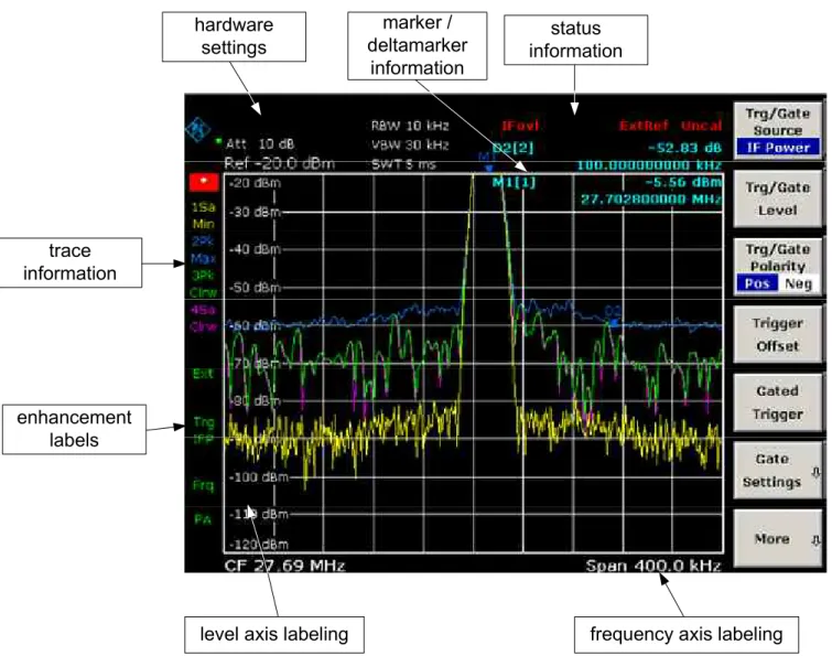
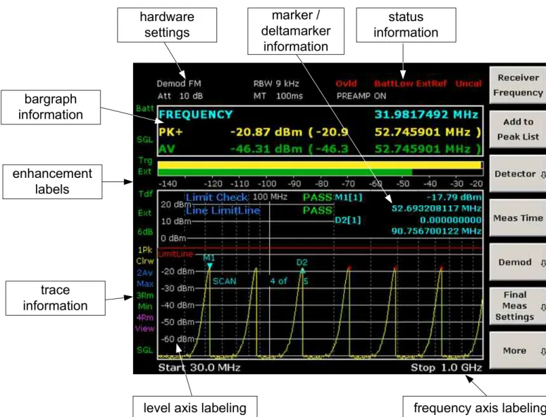
Information in the Diagram Area ... 4.2 Display of Hardware Settings in receiver mode... 4.4 Display of Hardware Settings in analyzer mode... 4.5 Status Displays... 4.6 Trace Information ... 4.7 Enhancement Labels... 4.8 Setting Parameters... 4.9 Keypad ... 4.9 Rotary Knob ... 4.10 Arrow and Position Keys ... 4.11 Softkeys ... 4.12 Dialog Boxes ... 4.13 To enter numeric parameters ... 4.13To navigate in dialog boxes ... 4.15 Specialties in Windows dialog boxes ... 4.18 How to Use the Help System... 4.19 To call context–sensitive and non context–sensitive help ... 4.19 To navigate in the table of contents ... 4.19 To navigate in the help topics (with front panel keys)... 4.19 To search for a topic ... 4.19 To change the zoom ... 4.20 To close the help window... 4.20
5 Basic Measurement Examples... 5.1
Performing a Level and Frequency Measurement ... 5.2 Measuring a Sinusoidal Signal ... 5.7 Measuring the Level and Frequency Using Markers... 5.7 Increasing the Frequency Resolution... 5.8 Setting the Reference Level... 5.9 Measuring the Signal Frequency Using the Frequency Counter... 5.10 Measuring Harmonics of Sinusoidal Signals ... 5.12 Measuring the Suppression of the First and Second Harmonic of an Input Signal 5.12 Reducing Noise... 5.13 Measuring Signal Spectra with Multiple Signals... 5.15 Separating Signals by Selecting the Resolution Bandwidth... 5.15Separating Two Signals with a Level of –30 dBm each at a Frequency
Spacing of 30 kHz... 5.16 Measuring the Modulation Depth of an AM–Modulated Carrier (Span > 0) ... 5.19 Measuring of AM–Modulated Signals ... 5.21 Displaying the AF of an AM–Modulated Signal (Zero Span) ... 5.21 Measurements in Zero Span ... 5.22 Measuring the Power Characteristic of Burst Signals ... 5.23 Measuring the Power of a GSM Burst During the Activation Phase... 5.23 Measuring the Edges of a GSM Burst with High Time Resolution ... 5.24 Measuring the Signal–to–Noise Ratio of Burst Signals... 5.26 Signal–to–Noise Ratio of a GSM Signal... 5.27 Measuring of FM–Modulated Signals ... 5.29 Displaying the AF of an FM–Modulated Carrier ... 5.30 Storing and Loading Instrument Settings... 5.32 Storing an Instrument Configuration (without Traces)... 5.33 Storing Traces ... 5.34
Loading an Instrument Configuration (with Traces)... 5.34 Configuring Automatic Loading ... 5.35
6 Brief Introduction to Remote Control... 6.1
Basic Steps in Remote Control Programming... 6.2 Linking the Remote Control Library for Visual Basic ... 6.2 Initialization and Default State... 6.5 Creating Global Variables... 6.5 Initializing the Remote Control Session ... 6.5 Initializing the Instrument... 6.6 Switching the Screen Display On and Off... 6.6 Configuring the Power Save Function for the Display ... 6.7 Sending Simple Instrument Setting Commands... 6.7 Switching to Manual Operation ... 6.7 Reading Out Instrument Settings ... 6.8 Marker Positioning and Readout ... 6.8 Command Synchronization ... 6.9 Reading Output Buffers ... 6.10 Reading Error Messages... 6.10 Detailed Programming Examples... 6.10 Default Setting of the R&S ESL... 6.10 Setting the Remote Control Status Registers ... 6.11 Default Settings for Measurements ... 6.11 Using Markers and Delta Markers... 6.13 Marker Search Functions, Restricting the Search Range... 6.13 Frequency Counting ... 6.15 Working with a Fixed Reference Point... 6.15 Measuring Noise and Phase Noise ... 6.16 Reading Out Trace Data ... 6.18 Storing and Loading Instrument Settings ... 6.19 Storing Instrument Settings ... 6.20 Loading Instrument Settings ... 6.20 Setting the Data Record for Startup Recall... 6.21 Configuring and Starting a Printout ... 6.21 Appendix A: Printer Interface... A.1 Installing Local Printers ...A.1 To install a local printer...A.1Appendix B: LAN Interface...B.1 Configuring the Network ... B.1 To change the computer name ... B.2 To change the domain or workgroup... B.2 To operate the instrument without a network ... B.3 To create users ... B.3 To change the user password... B.5 To log on to the network... B.6 To deactivate the automatic login mechanism ... B.6 To reactivate the automatic login mechanism ... B.6 To map network drives... B.7 To disconnect network drives... B.8 To install a network printer ... B.8 To share directories (only with Microsoft networks) ... B.13 Remote Operation with XP Remote Desktop... B.14 To configure the R&S ESL for remote operation... B.14 To configure the controller ... B.17 To set up a connection to the R&S ESL... B.21 To end Remote Desktop control ... B.23 To restore the connection to the R&S ESL ... B.24 To deactivate the R&S ESL via remote operation... B.24 RSIB Protocol ... B.24
Make sure to read through and observe the following safety instructions!
All plants and locations of the Rohde & Schwarz group of companies make every effort to keep the safety standard of our products up to date and to offer our customers the highest possible degree of safety. Our products and the auxiliary equipment required for them are designed and tested in accordance with the relevant safety standards. Compliance with these standards is continuously monitored by our quality assurance system. The product described here has been designed and tested in accordance with the EC Certificate of Conformity and has left the manufacturer’s plant in a condition fully complying with safety standards. To maintain this condition and to ensure safe operation, observe all instructions and warnings provided in this manual. If you have any questions regarding these safety instructions, the Rohde & Schwarz group of companies will be happy to answer them.
Furthermore, it is your responsibility to use the product in an appropriate manner. This product is designed for use solely in industrial and laboratory environments or, if expressly permitted, also in the field and must not be used in any way that may cause personal injury or property damage. You are responsible if the product is used for an intention other than its designated purpose or in disregard of the manufacturer's instructions. The manufacturer shall assume no responsibility for such use of the product.
The product is used for its designated purpose if it is used in accordance with its product documentation and within its performance limits (see data sheet, documentation, the following safety instructions). Using the product requires technical skills and a basic knowledge of English. It is therefore essential that only skilled and specialized staff or thoroughly trained personnel with the required skills be allowed to use the product. If personal safety gear is required for using Rohde & Schwarz products, this will be indicated at the appropriate place in the product documentation. Keep the basic safety instructions and the product documentation in a safe place and pass them on to the subsequent users.
Symbols and safety labels
Observe product documentation Weight indication for units >18 kg Danger of electric shock Warning! Hot surface PE
terminal Ground Ground terminal
Attention! Electrostatic sensitive devices Supply voltage ON/OFF Standby indication Direct current (DC) Alternating current (AC) Direct/alternating current (DC/AC) Device fully protected by double/reinforced insulation
caused by dangerous situations. Therefore, carefully read through and adhere to the following safety instructions before putting the product into operation. It is also absolutely essential to observe the additional safety instructions on personal safety that appear in relevant parts of the product documentation. In these safety instructions, the word "product" refers to all merchandise sold and distributed by the Rohde & Schwarz group of companies, including instruments, systems and all accessories.
Tags and their meaning
DANGER DANGER indicates a hazardous situation which, if not avoided, will result in death or serious injury.
WARNING WARNING indicates a hazardous situation which, if not avoided, could result in death or serious injury.
CAUTION CAUTION indicates a hazardous situation which, if not avoided, may result in minor or moderate injury.
NOTICE NOTICE indicates a property damage message.
In the product documentation, the word ATTENTION is used synonymously.
These tags are in accordance with the standard definition for civil applications in the European Economic Area. Definitions that deviate from the standard definition may also exist in other economic areas or military applications. It is therefore essential to make sure that the tags described here are always used only in connection with the related product documentation and the related product. The use of tags in connection with unrelated products or documentation can result in misinterpretation and thus contribute to personal injury or material damage.
Basic safety instructions
1. The product may be operated only underthe operating conditions and in the positions specified by the manufacturer. Its ventilation must not be obstructed during operation. Unless otherwise specified, the following requirements apply to Rohde & Schwarz products: prescribed operating position is always with the housing floor facing down, IP protection 2X, pollution severity 2, overvoltage category 2, use only in enclosed spaces, max. operation altitude 2000 m above sea level, max. transport altitude 4500 m above sea level.
A tolerance of ±10% shall apply to the nominal voltage and of ±5% to the nominal frequency.
2. Applicable local or national safety regulations and rules for the prevention
of accidents must be observed in all work performed. The product may be opened only by authorized, specially trained personnel. Prior to performing any work on the product or opening the product, the product must be
disconnected from the supply network. Any adjustments, replacements of parts, maintenance or repair must be carried out only by technical personnel
authorized by Rohde & Schwarz. Only original parts may be used for replacing parts relevant to safety (e.g. power switches, power transformers, fuses). A safety test must always be performed after parts relevant to safety have been replaced (visual inspection, PE
conductor test, insulation resistance measurement, leakage current measurement, functional test).
training and intense concentration. Make certain that persons who use the
products are physically, mentally and emotionally fit enough to handle operating the products; otherwise
injuries or material damage may occur. It is the responsibility of the employer to select suitable personnel for operating the products.
goods, the use of substances that induce an allergic reaction (allergens, e.g. nickel) such as aluminum cannot be generally excluded. If you develop an allergic reaction (such as a skin rash, frequent sneezing, red eyes or
respiratory difficulties), consult a
physician immediately to determine the cause.
8. Prior to switching on the product, it must be ensured that the nominal voltage setting on the product matches the nominal voltage of the AC supply network. If a different voltage is to be set, the power fuse of the product may have to be changed accordingly. 4. If products/components are
mechanically and/or thermically processed in a manner that goes beyond their intended use, hazardous substances (heavy-metal dust such as lead, beryllium, nickel) may be released. For this reason, the product may only be disassembled, e.g. for disposal
purposes, by specially trained
personnel. Improper disassembly may be hazardous to your health. National waste disposal regulations must be observed.
9. In the case of products of safety class I with movable power cord and connector, operation is permitted only on sockets with earthing contact and protective earth connection.
10. Intentionally breaking the protective earth connection either in the feed line or in the product itself is not permitted. Doing so can result in the danger of an electric shock from the product. If extension cords or connector strips are implemented, they must be checked on a regular basis to ensure that they are safe to use.
5. If handling the product yields hazardous substances or fuels that must be
disposed of in a special way, e.g. coolants or engine oils that must be replenished regularly, the safety instructions of the manufacturer of the hazardous substances or fuels and the applicable regional waste disposal regulations must be observed. Also observe the relevant safety instructions in the product documentation.
11. If the product has no power switch for disconnection from the AC supply, the plug of the connecting cable is regarded as the disconnecting device. In such cases, it must be ensured that the power plug is easily reachable and accessible at all times (corresponding to the length of connecting cable, approx. 2 m). Functional or electronic switches are not suitable for providing disconnection from the AC supply. If products without power switches are integrated in racks or systems, a disconnecting device must be provided at the system level. 6. Depending on the function, certain
products such as RF radio equipment can produce an elevated level of electromagnetic radiation. Considering that unborn life requires increased protection, pregnant women should be protected by appropriate measures. Persons with pacemakers may also be endangered by electromagnetic
radiation. The employer/operator is required to assess workplaces where there is a special risk of exposure to radiation and, if necessary, take measures to avert the danger.
is damaged. Check the power cable on a regular basis to ensure that it is in proper operating condition. By taking appropriate safety measures and
carefully laying the power cable, ensure that the cable cannot be damaged and that no one can be hurt by e.g. tripping over the cable or suffering an electric shock.
13. The product may be operated only from TN/TT supply networks fused with max. 16 A (higher fuse only after consulting with the Rohde & Schwarz group of companies).
14. Do not insert the plug into sockets that are dusty or dirty. Insert the plug firmly and all the way into the socket.
Otherwise, this can result in sparks, fire and/or injuries.
15. Do not overload any sockets, extension cords or connector strips; doing so can cause fire or electric shocks.
16. For measurements in circuits with voltages Vrms > 30 V, suitable measures
(e.g. appropriate measuring equipment, fusing, current limiting, electrical
separation, insulation) should be taken to avoid any hazards.
17. Ensure that the connections with information technology equipment comply with IEC 950/EN 60950. 18. Unless expressly permitted, never
remove the cover or any part of the housing while the product is in
operation. Doing so will expose circuits and components and can lead to injuries, fire or damage to the product. 19. If a product is to be permanently
installed, the connection between the PE terminal on site and the product's PE conductor must be made first before any other connection is made. The product may be installed and connected only by a license electrician.
20. For permanently installed equipment without built-in fuses, circuit breakers or similar protective devices, the supply circuit must be fused in such a way that
and products.
21. Do not insert any objects into the openings in the housing that are not designed for this purpose. Never pour any liquids onto or into the housing. This can cause short circuits inside the
product and/or electric shocks, fire or injuries.
22. Use suitable overvoltage protection to ensure that no overvoltage (such as that caused by a thunderstorm) can reach the product. Otherwise the operating personnel will be endangered by electric shocks.
23. Rohde & Schwarz products are not protected against penetration of liquids, unless otherwise specified (see also safety instruction 1.). If this is not taken into account, there exists the danger of electric shock for the user or damage to the product, which can also lead to personal injury.
24. Never use the product under conditions in which condensation has formed or can form in or on the product, e.g. if the product was moved from a cold to a warm environment.
25. Do not close any slots or openings on the product, since they are necessary for ventilation and prevent the product from overheating. Do not place the product on soft surfaces such as sofas or rugs or inside a closed housing, unless this is well ventilated.
26. Do not place the product on
heat-generating devices such as radiators or fan heaters. The temperature of the environment must not exceed the maximum temperature specified in the data sheet.
27. Batteries and storage batteries must not be exposed to high temperatures or fire. Keep batteries and storage batteries away from children. Do not short-circuit batteries and storage batteries.
If batteries or storage batteries are improperly replaced, this can cause an explosion (warning: lithium cells).
only with the matching Rohde & Schwarz type (see spare parts list). Batteries and storage batteries must be recycled and kept separate from residual waste. Batteries and storage batteries that contain lead, mercury or cadmium are hazardous waste. Observe the national regulations regarding waste disposal and recycling.
28. Please be aware that in the event of a fire, toxic substances (gases, liquids etc.) that may be hazardous to your health may escape from the product. 29. The product can be very heavy. Be
careful when moving it to avoid back or other physical injuries.
30. Do not place the product on surfaces, vehicles, cabinets or tables that for reasons of weight or stability are unsuitable for this purpose. Always follow the manufacturer's installation instructions when installing the product and fastening it to objects or structures (e.g. walls and shelves).
31. Handles on the products are designed exclusively for personnel to hold or carry the product. It is therefore not
permissible to use handles for fastening the product to or on means of transport such as cranes, fork lifts, wagons, etc. The user is responsible for securely fastening the products to or on the
safety regulations of the manufacturer of the means of transport. Noncompliance can result in personal injury or material damage.
32. If you use the product in a vehicle, it is the sole responsibility of the driver to drive the vehicle safely. Adequately secure the product in the vehicle to prevent injuries or other damage in the event of an accident. Never use the product in a moving vehicle if doing so could distract the driver of the vehicle. The driver is always responsible for the safety of the vehicle. The manufacturer assumes no responsibility for accidents or collisions.
33. If a laser product (e.g. a CD/DVD drive) is integrated in a Rohde & Schwarz product, do not use any other settings or functions than those described in the product documentation. Otherwise this may be hazardous to your health, since the laser beam can cause irreversible damage to your eyes. Never try to take such products apart, and never look into the laser beam.
34. Prior to cleaning, disconnect the product from the AC supply. Use a soft, non-linting cloth to clean the product. Never use chemical cleaning agents such as alcohol, acetone or diluent for cellulose lacquers.
Informaciones elementales de seguridad
¡Es imprescindible leer y observar las siguientes instrucciones e
informaciones de seguridad!
El principio del grupo de empresas Rohde & Schwarz consiste en tener nuestros productos siempre al día con los estándares de seguridad y de ofrecer a nuestros clientes el máximo grado de seguridad. Nuestros productos y todos los equipos adicionales son siempre fabricados y examinados según las normas de seguridad vigentes. Nuestra sección de gestión de la seguridad de calidad controla constantemente que sean cumplidas estas normas. El presente producto ha sido fabricado y examinado según el comprobante de conformidad adjunto según las normas de la CE y ha salido de nuestra planta en estado impecable según los estándares técnicos de seguridad. Para poder preservar este estado y garantizar un funcionamiento libre de peligros, el usuario deberá atenerse a todas las indicaciones, informaciones de seguridad y notas de alerta. El grupo de empresas Rohde & Schwarz está siempre a su disposición en caso de que tengan preguntas referentes a estas informaciones de seguridad.
Además queda en la responsabilidad del usuario utilizar el producto en la forma debida. Este producto está destinado exclusivamente al uso en la industria y el laboratorio o, si ha sido expresamente autorizado, para aplicaciones de campo y de ninguna manera deberá ser utilizado de modo que alguna persona/cosa pueda sufrir daño. El uso del producto fuera de sus fines definidos o despreciando las informaciones de seguridad del fabricante queda en la responsabilidad del usuario. El fabricante no se hace en ninguna forma responsable de consecuencias a causa del mal uso del producto.
Se parte del uso correcto del producto para los fines definidos si el producto es utilizado dentro de las instrucciones de la correspondiente documentación de producto y dentro del margen de rendimiento definido (ver hoja de datos, documentación, informaciones de seguridad que siguen). El uso del producto hace necesarios conocimientos profundos y conocimientos básicas del idioma inglés. Por eso se debe tener en cuenta que el producto sólo pueda ser operado por personal especializado o personas minuciosamente instruidas con las capacidades correspondientes. Si fuera necesaria indumentaria de seguridad para el uso de productos de R&S, encontrará la información debida en la documentación del producto en el capítulo correspondiente. Guarde bien las informaciones de seguridad elementales, así como la documentación del producto y entréguela a usuarios posteriores.
Símbolos y definiciones de seguridad
Ver documen-tación de producto Informaciones para maquinaria con un peso de > 18kg Peligro de golpe de corriente ¡Advertencia! Superficie caliente Conexión a conductor protector Conexión a tierra Conexión a masa conductora ¡Cuidado! Elementos de construcción con peligro de carga electroestática
Potencia EN
MARCHA/PARADA Indicación Stand-by
Corriente continua DC Corriente alterna AC Corriente continua/alterna DC/AC
El aparato está protegido en su totalidad por un
aislamiento de doble refuerzo
Tener en cuenta las informaciones de seguridad sirve para tratar de evitar daños y peligros de toda clase. Es necesario de que se lean las siguientes informaciones de seguridad concienzudamente y se tengan en cuenta debidamente antes de la puesta en funcionamiento del producto. También deberán ser tenidas en cuenta las informaciones para la protección de personas que encontrarán en el capítulo correspondiente de la documentación de producto y que también son obligatorias de seguir. En las informaciones de seguridad actuales hemos juntado todos los objetos vendidos por el grupo de empresas Rohde & Schwarz bajo la denominación de „producto“, entre ellos también aparatos, instalaciones así como toda clase de accesorios.
Palabras de señal y su significado
PELIGRO Identifica un peligro directo con riesgo elevado de provocar muerte o lesiones de gravedad si no se toman las medidas oportunas.
ADVERTENCIA Identifica un posible peligro con riesgo medio de provocar muerte o lesiones (de gravedad) si no se toman las medidas oportunas.
ATENCIÓN Identifica un peligro con riesgo reducido de provocar lesiones de gravedad media o leve si no se toman las medidas oportunas.
AVISO Indica la posibilidad de utilizar mal el producto y a consecuencia dañarlo.
En la documentación del producto se emplea de forma sinónima el término CUIDADO.
Las palabras de señal corresponden a la definición habitual para aplicaciones civiles en el área económica europea. Pueden existir definiciones diferentes a esta definición en otras áreas económicas o en aplicaciones militares. Por eso se deberá tener en cuenta que las palabras de señal aquí descritas sean utilizadas siempre solamente en combinación con la correspondiente documentación de producto y solamente en combinación con el producto correspondiente. La utilización de las palabras de señal en combinación con productos o documentaciones que no les correspondan puede llevar a malinterpretaciones y tener por consecuencia daños en personas u objetos.
Informaciones de seguridad elementales
general de que se produzcan al usarlo elementos que puedan generar alergias, los llamados elementos alergénicos (por ejemplo el níquel). Si se producieran en el trato con productos R&S reacciones alérgicas, como por ejemplo urticaria, estornudos frecuentes, irritación de la conjuntiva o dificultades al respirar, se deberá consultar inmediatamente a un médico para averiguar los motivos de estas reacciones.
1. El producto solamente debe ser utilizado según lo indicado por el fabricante
referente a la situación y posición de funcionamiento sin que se obstruya la ventilación. Si no se convino de otra manera, es para los productos R&S válido lo que sigue:
como posición de funcionamiento se define por principio la posición con el suelo de la caja para abajo, modo de protección IP 2X, grado de suciedad 2, categoría de sobrecarga eléctrica 2, utilizar solamente en estancias interiores, utilización hasta 2000 m sobre el nivel del mar, transporte hasta 4.500 m sobre el nivel del mar.
Se aplicará una tolerancia de ±10% sobre el voltaje nominal y de ±5% sobre la frecuencia nominal.
4. Si productos / elementos de
construcción son tratados fuera del funcionamiento definido de forma mecánica o térmica, pueden generarse elementos peligrosos (polvos de
sustancia de metales pesados como por ejemplo plomo, berilio, níquel). La
partición elemental del producto, como por ejemplo sucede en el tratamiento de materias residuales, debe de ser
efectuada solamente por personal especializado para estos tratamientos. La partición elemental efectuada
inadecuadamente puede generar daños para la salud. Se deben tener en cuenta las directivas nacionales referentes al tratamiento de materias residuales. 2. En todos los trabajos deberán ser
tenidas en cuenta las normas locales de seguridad de trabajo y de prevención de accidentes. El producto solamente debe de ser abierto por personal
especializado autorizado. Antes de efectuar trabajos en el producto o abrirlo deberá este ser desconectado de la corriente. El ajuste, el cambio de partes, la manutención y la reparación deberán ser solamente efectuadas por
electricistas autorizados por R&S. Si se reponen partes con importancia para los aspectos de seguridad (por ejemplo el enchufe, los transformadores o los fusibles), solamente podrán ser sustituidos por partes originales. Después de cada recambio de partes elementales para la seguridad deberá ser efectuado un control de seguridad (control a primera vista, control de conductor protector, medición de
resistencia de aislamiento, medición de la corriente conductora, control de funcionamiento).
5. En el caso de que se produjeran
agentes de peligro o combustibles en la aplicación del producto que debieran de ser transferidos a un tratamiento de materias residuales, como por ejemplo agentes refrigerantes que deben ser repuestos en periodos definidos, o aceites para motores, deberán ser tenidas en cuenta las prescripciones de seguridad del fabricante de estos
agentes de peligro o combustibles y las regulaciones regionales para el
tratamiento de materias residuales. Cuiden también de tener en cuenta en caso dado las prescripciones de
seguridad especiales en la descripción del producto.
3. Como en todo producto de fabricación industrial no puede ser excluido en
utilizaran cables o enchufes de extensión se deberá poner al seguro que es controlado su estado técnico de seguridad.
instalaciones de radiocomunicación RF, pueden a causa de su función natural, emitir una radiación electromagnética aumentada. En vista a la protección de la vida en desarrollo deberían ser protegidas personas embarazadas debidamente. También las personas con un bypass pueden correr peligro a causa de la radiación electromagnética. El empresario/usuario está comprometido a valorar y señalar áreas de trabajo en las que se corra un riesgo aumentado de exposición a radiaciones para evitar riesgos.
11. Si el producto no está equipado con un interruptor para desconectarlo de la red, se deberá considerar el enchufe del cable de distribución como interruptor. En estos casos deberá asegurar de que el enchufe sea de fácil acceso y nabejo (según la medida del cable de
distribución, aproximadamente 2 m). Los interruptores de función o electrónicos no son aptos para el corte de la red eléctrica. Si los productos sin interruptor están integrados en bastidores o
instalaciones, se deberá instalar el interruptor al nivel de la instalación. 7. La utilización de los productos requiere
instrucciones especiales y una alta concentración en el manejo. Debe de ponerse por seguro de que las personas que manejen los productos estén a la altura de los requerimientos necesarios referente a sus aptitudes físicas,
psíquicas y emocionales, ya que de otra manera no se pueden excluir lesiones o daños de objetos. El empresario lleva la responsabilidad de seleccionar el
personal usuario apto para el manejo de los productos.
12. No utilice nunca el producto si está dañado el cable eléctrico. Compruebe regularmente el correcto estado de los cables de conexión a red. Asegure a través de las medidas de protección y de instalación adecuadas de que el cable de eléctrico no pueda ser dañado o de que nadie pueda ser dañado por él, por ejemplo al tropezar o por un golpe de corriente.
8. Antes de la puesta en marcha del producto se deberá tener por seguro de que la tensión preseleccionada en el producto equivalga a la del la red de distribución. Si es necesario cambiar la preselección de la tensión también se deberán en caso dabo cambiar los fusibles correspondientes del producto.
13. Solamente está permitido el
funcionamiento en redes de distribución TN/TT aseguradas con fusibles de como máximo 16 A (utilización de fusibles de mayor amperaje sólo previa consulta con el grupo de empresas Rohde & Schwarz).
9. Productos de la clase de seguridad I con alimentación móvil y enchufe individual de producto solamente deberán ser conectados para el funcionamiento a tomas de corriente de contacto de seguridad y con conductor protector conectado.
14. Nunca conecte el enchufe en tomas de corriente sucias o llenas de polvo. Introduzca el enchufe por completo y fuertemente en la toma de corriente. Si no tiene en consideración estas
indicaciones se arriesga a que se originen chispas, fuego y/o heridas. 10. Queda prohibida toda clase de
interrupción intencionada del conductor protector, tanto en la toma de corriente como en el mismo producto. Puede tener como consecuencia el peligro de
15. No sobrecargue las tomas de corriente, los cables de extensión o los enchufes de extensión ya que esto pudiera causar fuego o golpes de corriente.
corriente con una tensión de entrada de Ueff > 30 V se deberá tomar las
precauciones debidas para impedir cualquier peligro (por ejemplo medios de medición adecuados, seguros, limitación de tensión, corte protector, aislamiento etc.).
17. En caso de conexión con aparatos de la técnica informática se deberá tener en cuenta que estos cumplan los requisitos del estándar IEC950/EN60950.
18. A menos que esté permitido
expresamente, no retire nunca la tapa ni componentes de la carcasa mientras el producto esté en servicio. Esto pone a descubierto los cables y componentes eléctricos y puede causar heridas, fuego o daños en el producto.
19. Si un producto es instalado fijamente en un lugar, se deberá primero conectar el conductor protector fijo con el conductor protector del aparato antes de hacer cualquier otra conexión. La instalación y la conexión deberán ser efectuadas por un electricista especializado.
20. En caso de que los productos que son instalados fijamente en un lugar sean sin protector implementado, autointerruptor o similares objetos de protección, el circuito de suministro de corriente deberá estar protegido de manera que usuarios y productos estén
suficientemente protegidos.
21. Por favor, no introduzca ningún objeto que no esté destinado a ello en los orificios de la caja del aparato. No vierta nunca ninguna clase de líquidos sobre o en la caja. Esto puede producir
cortocircuitos en el producto y/o puede causar golpes de corriente, fuego o heridas.
22. Asegúrese con la protección adecuada de que no pueda originarse en el
producto una sobrecarga por ejemplo a causa de una tormenta. Si no se verá el personal que lo utilice expuesto al peligro de un golpe de corriente.
23. Los productos R&S no están protegidos contra líquidos si no es que exista otra
tiene en cuenta esto se arriesga el peligro de golpe de corriente para el usuario o de daños en el producto lo cual también puede llevar al peligro de personas.
24. No utilice el producto bajo condiciones en las que pueda producirse y se hayan producido líquidos de condensación en o dentro del producto como por ejemplo cuando se desplaza el producto de un lugar frío a un lugar caliente.
25. Por favor no cierre ninguna ranura u orificio del producto, ya que estas son necesarias para la ventilación e impiden que el producto se caliente demasiado. No pongan el producto encima de materiales blandos como por ejemplo sofás o alfombras o dentro de una caja cerrada, si esta no está suficientemente ventilada.
26. No ponga el producto sobre aparatos que produzcan calor, como por ejemplo radiadores o calentadores. La
temperatura ambiental no debe superar la temperatura máxima especificada en la hoja de datos.
27. Baterías y acumuladores no deben de ser expuestos a temperaturas altas o al fuego. Guardar baterías y acumuladores fuera del alcance de los niños. No
cortocircuitar baterías ni acumuladores. Si las baterías o los acumuladores no son cambiados con la debida atención existirá peligro de explosión (atención células de litio). Cambiar las baterías o los acumuladores solamente por los del tipo R&S correspondiente (ver lista de piezas de recambio). Las baterías y acumuladores deben reutilizarse y no deben acceder a los vertederos. Las baterías y acumuladores que contienen plomo, mercurio o cadmio deben
tratarse como residuos especiales. Respete en esta relación las normas nacionales de evacuación y reciclaje. 28. Por favor tengan en cuenta que en caso
de un incendio pueden desprenderse del producto agentes venenosos (gases, líquidos etc.) que pueden generar daños a la salud.
elevado. Muévalo con cuidado para evitar lesiones en la espalda u otras partes corporales.
30. No sitúe el producto encima de superficies, vehículos, estantes o mesas, que por sus características de peso o de estabilidad no sean aptas para él. Siga siempre las instrucciones de instalación del fabricante cuando instale y asegure el producto en objetos o estructuras (por ejemplo paredes y estantes).
31. Las asas instaladas en los productos sirven solamente de ayuda para el manejo que solamente está previsto para personas. Por eso no está permitido utilizar las asas para la sujeción en o sobre medios de transporte como por ejemplo grúas, carretillas elevadoras de horquilla, carros etc. El usuario es responsable de que los productos sean sujetados de forma segura a los medios de transporte y de que las prescripciones de
seguridad del fabricante de los medios de transporte sean observadas. En caso de que no se tengan en cuenta pueden causarse daños en personas y objetos. 32. Si llega a utilizar el producto dentro de
un vehículo, queda en la
responsabilidad absoluta del conductor
segura. Asegure el producto dentro del vehículo debidamente para evitar en caso de un accidente las lesiones u otra clase de daños. No utilice nunca el producto dentro de un vehículo en movimiento si esto pudiera distraer al conductor. Siempre queda en la
responsabilidad absoluta del conductor la seguridad del vehículo. El fabricante no asumirá ninguna clase de
responsabilidad por accidentes o colisiones.
33. Dado el caso de que esté integrado un producto de láser en un producto R&S (por ejemplo CD/DVD-ROM) no utilice otras instalaciones o funciones que las descritas en la documentación de producto. De otra manera pondrá en peligro su salud, ya que el rayo láser puede dañar irreversiblemente sus ojos. Nunca trate de descomponer estos productos. Nunca mire dentro del rayo láser.
34. Antes de proceder a la limpieza, desconecte el producto de la red. Realice la limpieza con un paño suave, que no se deshilache. No utilice de ninguna manera agentes limpiadores químicos como, por ejemplo, alcohol, acetona o nitrodiluyente.
Kundeninformation zur Batterieverordnung
(BattV)
Dieses Gerät enthält eine schadstoffhaltige Batterie. Diese darf nicht mit dem Hausmüll entsorgt werden. Nach Ende der Lebensdauer darf die Entsorgung nur über eine Rohde&Schwarz-Kundendienststelle oder eine geeignete Sammelstelle erfolgen.
Safety Regulations for Batteries
(according to BattV)
This equipment houses a battery containing harmful substances that must not be disposed of as normal household waste.
After its useful life, the battery may only be disposed of at a Rohde & Schwarz service center or at a suitable depot.
Normas de Seguridad para Baterías
(Según BattV)
Este equipo lleva una batería que contiene sustancias perjudiciales, que no se debe desechar en los
contenedores de basura domésticos.
Después de la vida útil, la batería sólo se podrá eliminar en un centro de servicio de Rohde & Schwarz o en un depósito apropiado.
Consignes de sécurité pour batteries
(selon BattV)
Cet appareil est équipé d'une pile comprenant des substances nocives. Ne jamais la jeter dans une poubelle pour ordures ménagéres.
Une pile usagée doit uniquement être éliminée par un centre de service client de Rohde & Schwarz ou peut être collectée pour être traitée spécialement comme déchets dangereux.
The German Electrical and Electronic Equipment (ElektroG) Act is an implementation of
the following EC directives:
•
2002/96/EC on waste electrical and electronic equipment (WEEE) and
•
2002/95/EC on the restriction of the use of certain hazardous substances in
electrical and electronic equipment (RoHS).
Product labeling in accordance with EN 50419
Once the lifetime of a product has ended, this product must not be disposed of
in the standard domestic refuse. Even disposal via the municipal collection
points for waste electrical and electronic equipment is not permitted.
Rohde & Schwarz GmbH & Co. KG has developed a disposal concept for the
environmental-friendly disposal or recycling of waste material and fully assumes its
obligation as a producer to take back and dispose of electrical and electronic waste
in accordance with the ElektroG Act.
Sie haben sich für den Kauf eines Rohde & Schwarz-Produktes entschieden. Hiermit erhalten Sie ein nach modernsten Fertigungsme-thoden hergestelltes Produkt. Es wurde nach den Regeln unseres Managementsystems entwickelt, gefertigt und geprüft. Das Rohde & Schwarz
Managementsystem ist zertifiziert nach:
DIN EN ISO 9001:2000 DIN EN 9100:2003 DIN EN ISO 14001:2004
you have decided to buy a Rohde & Schwarz product. You are thus assured of receiving a product that is manufactured using the most modern methods available. This product was developed, manufactured and tested in compliance with our quality management system standards.
The Rohde & Schwarz quality management system is certified according to:
DIN EN ISO 9001:2000 DIN EN 9100:2003 DIN EN ISO 14001:2004
vous avez choisi d‘acheter un produit Rohde & Schwarz. Vous disposez donc d‘un produit fabriqué d‘après les méthodes les plus avancées. Le
développement, la fabrication et les tests respectent nos normes de gestion qualité.
Le système de gestion qualité de Rohde & Schwarz a été homologué conformément aux normes: DIN EN ISO 9001:2000 DIN EN 9100:2003 DIN EN ISO 14001:2004 74 4. 99 = V 01 .0 0 = M ay 20 07
Certificate No.: 2008-43 This is to certify that:
Equipment type Stock No. Designation
ESL3 1300.5001.03/.13 EMI Test Receiver ESL6 1300.5001.06/.16
FSL-B4 1300.6008.02 OCXO Reference Frequency FSL-B5 1300.6108.02 Additional Interfaces
FSL-B8 1300.5701.02 Gated Sweep Function FSL-B10 1300.6208.02 GPIB Interface
FSL-B22 1300.5953.02 RF Amplifier FSL-B30 1300.6308.02 DC Power Supply FSL-B31 1300.6408.02 NIMH Battery Pack FSL-Z4 1300.5430.02 Additional Charger Unit
complies with the provisions of the Directive of the Council of the European Union on the approximation of the laws of the Member States
- relating to electrical equipment for use within defined voltage limits (2006/95/EC)
- relating to electromagnetic compatibility (2004/108/EC)
Conformity is proven by compliance with the following standards: EN 61010-1 : 2001
EN 61326 : 1997 + A1 : 1998 + A2 : 2001 + A3 : 2003 EN 55011 : 1998 + A1 : 1999 + A2 : 2002, Klasse B EN 61000-3-2 : 2000 + A2 : 2005
EN 61000-3-3 : 1995 + A1 : 2001
For the assessment of electromagnetic compatibility, the limits of radio interference for Class B equipment as well as the immunity to interference for operation in industry have been used as a basis. Affixing the EC conformity mark as from 2008
ROHDE & SCHWARZ GmbH & Co. KG Mühldorfstr. 15, D-81671 München
Technical support – where and when you need it
For quick, expert help with any Rohde & Schwarz equipment, contact one of our Customer
Support Centers. A team of highly qualified engineers provides telephone support and will
work with you to find a solution to your query on any aspect of the operation, programming
or applications of Rohde & Schwarz equipment.
Up-to-date information and upgrades
To keep your instrument up-to-date and to be informed about new application notes related
to your instrument, please send an e-mail to the Customer Support Center stating your
instrument and your wish.
We will take care that you will get the right information.
USA & Canada
Monday to Friday
(except US public holidays)8:00 AM – 8:00 PM
Eastern Standard Time (EST)Tel. from USA
888-test-rsa (888-837-8772) (opt 2)
From outside USA
+1 410 910 7800 (opt 2)
Fax
+1 410 910 7801
[email protected]
East Asia
Monday to Friday
(except Singaporean public holidays)8:30 AM – 6:00 PM
Singapore Time (SGT)Tel.
+65 6 513 0488
Fax
+65 6 846 1090
[email protected]
Rest of the World
Monday to Friday
(except German public holidays)08:00 – 17:00
Central European Time (CET)Tel. from Europe
+49 (0) 180 512 42 42*
From outside Europe +49 89 4129 13776
Fax
+49 (0) 89 41 29 637 78
[email protected]
* 0.14 €/Min within the German fixed-line telephone network, varying prices for the mobile telephone network and in different countries.
12
Headquarters, Plants and SubsidiariesHeadquarters
ROHDE&SCHWARZ GmbH & Co. KG Mühldorfstraße 15 · D-81671 München P.O.Box 80 14 69 · D-81614 München Plants ROHDE&SCHWARZ Messgerätebau GmbH Riedbachstraße 58 · D-87700 Memmingen P.O.Box 16 52 · D-87686 Memmingen ROHDE&SCHWARZ GmbH & Co. KG Werk Teisnach
Kaikenrieder Straße 27 · D-94244 Teisnach P.O.Box 11 49 · D-94240 Teisnach ROHDE&SCHWARZ závod Vimperk, s.r.o. Location Spidrova 49 CZ-38501 Vimperk
ROHDE&SCHWARZ GmbH & Co. KG Dienstleistungszentrum Köln Graf-Zeppelin-Straße 18 · D-51147 Köln P.O.Box 98 02 60 · D-51130 Köln
Subsidiaries
R&S BICK Mobilfunk GmbH
Fritz-Hahne-Str. 7 · D-31848 Bad Münder P.O.Box 20 02 · D-31844 Bad Münder ROHDE&SCHWARZ FTK GmbH Wendenschloßstraße 168, Haus 28 D-12557 Berlin ROHDE&SCHWARZ SIT GmbH Am Studio 3 D-12489 Berlin R&S Systems GmbH Graf-Zeppelin-Straße 18 D-51147 Köln GEDIS GmbH Sophienblatt 100 D-24114 Kiel HAMEG Instruments GmbH Industriestraße 6 D-63533 Mainhausen Locations Worldwide
Please refer to our homepage: www.rohde-schwarz.com
◆Sales Locations ◆Service Locations ◆National Websites Phone +49 (89) 41 29-0 Fax +49 (89) 41 29-121 64 [email protected] Phone +49 (83 31) 1 08-0 +49 (83 31) 1 08-1124 [email protected] Phone +49 (99 23) 8 50-0 Fax +49 (99 23) 8 50-174 [email protected] Phone +420 (388) 45 21 09 Fax +420 (388) 45 21 13 Phone +49 (22 03) 49-0 Fax +49 (22 03) 49 51-229 [email protected] [email protected] Phone +49 (50 42) 9 98-0 Fax +49 (50 42) 9 98-105 [email protected] Phone +49 (30) 658 91-122 Fax +49 (30) 655 50-221 [email protected] Phone +49 (30) 658 84-0 Fax +49 (30) 658 84-183 [email protected] Phone +49 (22 03) 49-5 23 25 Fax +49 (22 03) 49-5 23 36 [email protected] Phone +49 (431) 600 51-0 Fax +49 (431) 600 51-11 [email protected] Phone +49 (61 82) 800-0 Fax +49 (61 82) 800-100 [email protected]
Documentation Overview
The user documentation for the R&S ESL is divided as follows:
• Quick Start Guide
• Online Help
• Operating Manual
• Service Manual
• Internet Site
• Release Notes
Quick Start Guide
This manual is delivered with the instrument in printed form and in PDF format on the CD. It provides the information needed to set up and start working with the instrument. Basic operations and basic measurements are described. Also a brief introduction to remote control is given. The manual includes general information (e.g. Safety Instructions) and the following chapters:
Chapter 1 Front and Rear Panel
Chapter 2 Putting into Operation
Chapter 3 Firmware Update and Installation of Firmware Options
Chapter 4 Basic Operations
Chapter 5 Basic Measurement Examples
Chapter 6 Brief Introduction to Remote Control
Appendix A Printer Interface
Appendix B LAN Interface
Online Help
The Online Help is part of the firmware. It provides a quick access to the description of the instrument functions and the remote control commands. For information on other topics refer to the Quick Start Guide, Operating Manual and Service Manual provided in PDF format on CD or in the Internet. For detailed information on how to use the Online Help, refer to the chapter "Basic Operations" in the Quick Start Guide.
Operating Manual
This manual is a supplement to the Quick Start Guide and is available in PDF format on the CD delivered with the instrument. To retain the familiar structure that applies to all operating manuals of Rohde&Schwarz Test & Measurement instruments, the chapters 1 and 3 exist, but only in form of references to the corresponding Quick Start Guide chapters.
In this manual, all instrument functions are described in detail. For additional information on default settings and parameters, refer to the data sheets. The set of measurement examples in the Quick Start Guide is expanded by more advanced measurement examples. In addition to the brief introduction to remote control in the Quick Start Guide, a description of the commands and programming examples is given. Information on maintenance, instrument interfaces and error messages is also provided.
The manual includes the following chapters:
Chapter 1 Putting into Operation, see Quick Start Guide
chapters 1 and 2
Chapter 2 Advanced Measurement Examples
Chapter 3 Manual Operation, see Quick Start Guide
chapter 4
Chapter 4 Instrument Functions
Chapter 5 Remote Control - Basics
Chapter 6 Remote Control - Commands
Chapter 7 Remote Control - Programming Examples
Chapter 8 Maintenance
Chapter 9 Error Messages
This manual is delivered with the instrument on CD only. The printed manual can be ordered from Rohde & Schwarz GmbH & Co. KG.
Service Manual
This manual is available in PDF format on the CD delivered with the instrument. It informs on how to check compliance with rated specifications, on instrument function, repair, troubleshooting and fault elimination. It contains all information required for repairing the R&S ESL by the replacement of modules. The manual includes the following chapters:
Chapter 1 Performance Test
Chapter 2 Adjustment
Chapter 3 Repair
Chapter 4 Software Update / Installing Options
Internet Site
The Internet site at: R&S ESL EMI Test Receiver provides the most up to date information
on the R&S ESL. The current operating manual at a time is available as printable PDF file in the download area.
Also provided for download are firmware updates including the associated release notes, instrument drivers, current data sheets and application notes.
Release Notes
The release notes describe the installation of the firmware, new and modified functions, eliminated problems, and last minute changes to the documentation. The corresponding firmware version is indicated on the title page of the release notes. The current release notes are provided in the Internet.
Conventions Used in the Documentation
To visualize important information quickly and to recognize information types faster, a few conventions has been introduced. The following character formats are used to emphasize words:
Bold All names of graphical user interface
elements as dialog boxes, softkeys, lists, options, buttons etc.
All names of user interface elements on the front and rear panel as keys, connectors etc.
Courier All remote commands (apart from
headings, see below)
Capital letters All key names (front panel or keyboard)
The description of a softkey (Operating Manual and Online Help) always starts with the softkey name, and is followed by explaining text and one or more remote control commands framed by two lines. Each remote command is placed in a single line.
The description of remote control commands (Operating Manual and Online Help) always starts with the command itself, and is followed by explaining text including an example, the characteristics and the mode (standard or only with certain options) framed by two grey lines. The remote commands consist of abbreviations to accelerate the procedure. All parts of the command that have to be entered are in capital letters, the rest is added in small letters to complete the words and transport their meaning.
1
Front and Rear Panel
This chapter describes the front panel and the rear panel of the instrument, including all function keys and connectors.
Front Panel View
Function Keys on the Front Panel
For details on the ON/STANDBY key refer to chapter 2, section "Power Supply Options". A detailed description of the corresponding menus and the other function keys is provided in the Operating Manual on CD or in the Online Help.
Function key Assigned functions
ON/STANDBY Switches the instrument on and off. For details on the standby mode (only available when the R&S ESL is supplied with AC power) refer to chapter 2, "Preparing for Use", section "Power Supply Options".
PRESET Resets the instrument to the default state.
FILE Provides the functions for storing/loading instrument settings and for managing stored files.
SETUP
Provides basic instrument configuration functions:
• Frequency reference (ext/int), noise source, video/IF output (option Additional Interfaces, R&S FSL–B5), transducer factors
• Date, time, display configuration
• LAN interface, remote control (option GPIB Interface, R&S FSL–B10)
• Self–alignment
• Firmware update and enabling of options
• Information about instrument configuration incl. firmware version and system error messages
• Service support functions (self test etc.)
• Transducer factors and LISN control
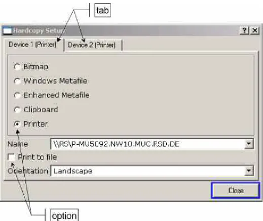
PRINT Customizes the printout, selects and configures the printer. HELP Displays the Online Help.
MODE Provides the selection between measurement modes and firmware options. MENU Jumps to the highest softkey menu level of the current measurement mode. FREQ Sets the center frequency as well as the start and stop frequencies for the frequency range under consideration. This key is also used to set the
frequency offset and the signal track function. SPAN Sets the frequency span to be analyzed.
In receiver mode, it opens the receiver main menu.
AMPT
Sets the reference level, the displayed dynamic range, the RF attenuation and the unit for the level display.
Sets the level offset and the input impedance. Activates the autoranging function.
Activates the preamplifier (option RF Preamplifier, R&S FSL–B22). BW Sets the resolution bandwidth and the video bandwidth.
SWEEP
Sets the stepped scan settings.
Sets the sweep time and the number of measurement points. Selects continuous measurement or single measurement. TRIG
Sets the trigger mode, the trigger threshold, the trigger delay, and the gate configuration in the case of gated sweep (option Gated Sweep, R&S FSL– B8).
Function key Assigned functions
MKR
Sets and positions the absolute and relative measurement markers (markers and delta markers). In addition, the following measurement functions are assigned under this key:
• Frequency counter
• Noise marker
• Phase noise marker
• Fixed reference point for relative measurement markers
• n dB down function
• AF demodulation
• Marker list
MKR–>
Used for search functions of the measurement markers (maximum/minimum of the trace).
Assigns the marker frequency to the center frequency, and the marker level to the reference level.
Restricts the search area and characterizes the maximum points and minimum points.
RUN Starts a new measurement, i.e. a stepped scan in receiver mode.
MEAS
In analyzer mode:
Used to perform advanced measurements:
• Time domain power
• Channel, adjacent channel and multicarrier adjacent channel power
• Occupied bandwidth
• Signal statistics: amplitude probability distribution (APD) and cumulative complementary distribution function (CCDF)
• Carrier to noise spacing
• AM modulation depth
• Third–order intercept point (TOI)
• Harmonics In receiver mode:
Opens the receiver main menu:
• Receiver frequency for bargraph measurement
• Detector for bargraph measurement
• Measurement time for bargraph measurement
• Demodulator
• Final measurement settings
LINES Configures display lines and limit lines.
Connectors on the Front Panel
All connectors on the front panel are placed on the bottom of the right–hand side. The inscriptions on your instrument are in match with the captions of the connector descriptions below.
Standard Front Panel Connectors
All connectors described in this chapter are provided by the R&S ESL models 03 and 06.
RF INPUT 50
The RF input is to be connected to the DUT via a cable equipped with a male N connector. It is AC–coupled.
NOTICE Instrument damage caused by disregarding the following
precautions!
Do not overload the input!
An input DC voltage of 50 V must never be exceeded in order to avoid damage to the instrument. The maximum continuous power at the RF input is 30 dBm (1 W).
PROBE POWER
The R&S ESL provides a connector for supply voltages of +15 V to –12 V and ground for active probes and preamplifiers. A maximum current of 140 mA is available. This connector is suitable as power supply for high–impedance probes from Agilent.
AF OUT
Headphones equipped with a miniature jack plug can be connected to the AF output female connector. To use the AF OUTPUT, in the setup menu (SETUP key), select video output. The output voltage (volume) is set via the marker menu or the MENU key.
CAUTION Risk of hearing damage
Using headphones can result in hearing damage.
Check the volume setting carefully before putting on the headphones in order to protect your hearing.
Note: This connector cannot be used simultaneously to the IF/Video output connector on the rear panel.
USB
The front panel provides two female USB connectors to connect devices like keyboard (recommended: R&S PSL–Z2, order number 1157.6870.04) and mouse (recommended: R&S PSL–Z10, order number 1157.7060.04). Also a memory stick can be connected to store and reload instrument settings and measurement data. Using an adapter cable (R&S NRP–Z4), a power sensor can be connected, as an alternative to the power sensor connector on the rear panel that is only available with option Additional Interfaces, R&S FSL–B5.
NOTICE Instrument damage caused by disregarding the following
precautions!
Use suitable double shielded cables. Passive USB connecting cables must not exceed 1 m in length.
Use only USB devices that keep the permissible EMI limits.
Optional Front Panel Connectors
The R&S ESL models 13 and 16 are equipped with a tracking generator and therefore provide a tracking generator output connector.
GEN OUTPUT 50
The output of the tracking generator is to be connected to the DUT via a cable equipped with a male N connector.
NOTICE Instrument damage caused by disregarding the following
precautions!
A reverse power of 1 W or 50 V DC must never be exceeded in order to avoid damage to the tracking generator.
Note: In the case of DUTs with sensitive RF characteristics with regard to matching (VSWR) at the input, insert a 10 dB attenuator between the DUT and the tracking generator.
Rear Panel View
Connectors on the Rear Panel
All standard connectors are placed at the bottom of the rear panel. Above all optional connectors are grouped according to their option. The inscriptions on your instrument or in Fig. 1–2 Rear panel view match with the captions of the connector descriptions below, if existing.
Standard Rear Panel Connectors
Unless otherwise stated, all connectors described in this chapter are provided by the standard models R&S ESL Var 03, R&S ESL Var 06, R&S ESL Var 13, R&S ESL Var 16.
AC power supply connector and AC power switch
The AC power supply connector and the AC power switch are located on the rear panel of the instrument. For an overview on available power supplies refer to chapter 2, "Preparing for Use", section "Power Supply Options".
AC power switch function:
Position I Depending on the setting of the ON/STANDBY function key on the front
panel, the instrument is either in standby mode or in operation.
Position O The entire instrument is disconnected from the AC power supply.
For details on switching on and off refer to chapter 2, sections "Switching On the Instrument" and "Switching Off the Instrument".
Note: The AC power switch also interrupts the power supply of the OCXO (option OCXO Reference Frequency, R&S FSL–B4). When switching the instrument back on, be sure to comply with the extended warm–up phase specified in the data sheet.
LAN
The LAN interface can be used to connect the R&S ESL to a local network for remote control, printouts and data transfer. The assignment of the RJ–45 connector supports twisted–pair category 5 UTP/STP cables in a star configuration (UTP stands for "unshielded twisted pair'', and STP for "shielded twisted pair'').
EXT TRIGGER / GATE IN
The female connector for external trigger/gate input is used to control the measurement by means of an external signal.
The voltage levels are TTL levels (low <0.7 V; high >1.4 V). The typical input impedance is 10 kO.
EXT REF
The setup menu is used to switch between the internal and an external reference. The external reference female connector is used as an input for a 10 MHz reference signal, if
Reference Ext is selected. The required input level is 0 dBm.
EXT REF with OCXO option (R&S FSL–B4)
This option generates a very precise 10 MHz reference signal with an output level of P 0 dBm for other devices. The standard connector EXT REF at the rear panel is used as output, but can also be used as input. Whether it is used as input or output is set via the setup menu: with Reference Ext as input, with Reference Int as output.
Note: The AC power switch also interrupts the power supply of the OCXO (option OCXO Reference Frequency, R&S FSL–B4). When you switch the instrument back on, be sure to comply with the extended warm–up phase specified in the data sheet.
MONITOR (DVI-D)
The female DVI-D connector is used to connect an external monitor. Step-by-step instructions how to connect an external monitor are provided in chapter 2, "Preparing for Use".
Note: The availability of the MONITOR connector depends on the serial number of the instrument.
Optional Rear Panel Connectors
All connectors described in this chapter are only provided, if the instrument is equipped with the indicated option.
POWER SENSOR (option Additional Interfaces, R&S FSL–B5)
The LEMOSA female connector is used for connecting power sensors of the R&S NRP–Zxy family. Alternatively, the USB port on the front panel can be used for this purpose, if an adapter cable R&S NRP–Z4 is supplied.