Energy Management
T. P. Ognisty, The M.W.Kellogg Company, Houston,TX,USA
Copyright^ 2000 Academic Press
Introduction
Distillation dominates separation processes in the petrochemical industry and consumes nearly 95% of the total energy used in commercial separations. The energy used in distillation is approximately 3% of the total energy consumed in US industry. Distillation columns provide reliable, cost-effective separation for large throughputs and high purity product requirements. Distillation is an energy-intensive process and economics drive the need to optimize energy consumption in all aspects of its design.
In the pioneer years of distillation development, energy was comparatively cheap compared to capital costs. ReSux ratios of 1.2}1.5 times the minimum were commonly used to obtain an economical balance between operating andRxed costs. Columns were designed with large design margins to allow for feed changes and the lack of accuracy in physical properties, tray hydraulics and tray efRciency. By providing excess exchanger and tray capacity, product purity could be maintained by adjusting the tower operation to compensate for design uncertainty.
With the advent of the oil crises of the 1970s and 1980s, the energy costs became the major factor in column costs and created an urgency toRnd ways to reduce the energy requirements of distillation. Several techniques for analysing columns and plants were extensively developed and published in this era. Among the notable advances is ‘exergy’ analysis, developed primarily in Europe, and ‘pinch’ techno-logy. This trend has subsided somewhat as more efRcient methods of design and experience have eventually replaced the older technologies. The more exciting opportunities are in revamping older plants and designing new products. The introduction of high speed computers has also played a signiRcant role in producing more accurate and more extensively eva-luated designs. Physical and transport properties continue to be obtained more accurately. As the regu-latory requirements for pollutant emissions and wastewater reduction became more stringent, many new studies has been directed towards reducing emis-sions from Rred heaters and steam boilers used to supply heating requirements in columns. Wastewater
reductions of steam condensate blowdowns and cool-ing water make-up have become subject to tighter restrictions. Distillation column design will become more extensive and complex as the stringency of requirements continues to increase.
The primary objective of distillation column design is to produce the desired products with the minimum amount of energy expenditure and capital cost. The energy consumption in distillation columns is affected by the physical properties of the system, the utilities available for heating and cooling, the internals for contacting the liquid and vapour and the arrangement of the column separation sequence.
Measurement of Energy Performance
In order to determine the energy performance of a distillation column, two thermodynamic principles are applied to give a measurement method for deter-mining the value of design improvements.
Availability or Exergy Analysis
The concept of availability or available useful work is a convenient way to determine the thermodynamic minimum amount of energy required for doing work in a steadySow process. The availability is referred to as exergy in Europe. The availability function is
de-Rned as:
A,H!TaS
whereHis the enthalpy,Sis the entropy andTais the
reference temperature (298 K). A higher value of availability indicates that more work can be extracted as compared to a lower value. For example, high pressure steam is more valuable than steam at atmos-pheric pressure, although the latent heat values are about equal.
The change in availability represents the amount of shaft work that can be extracted from a system as it Sows from an initial to Rnal state. It also deRnes the minimum work required to achieve a change in a Sowing system. This available shaft work, Ws, is deRned in terms of the availability
change, or:
!Ws,A"H!TaS
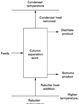
Figure 1 Distillation heat engine analogy.
Heat Engines
A Carnot heat engine is useful in determining the theoretical maximum heat efRciency of an ideal, reversible distillation. The heat engine analogy con-sists of the simple column arrangement depicted in
Figure 1. Heat is added at the bottom of the tower at a high level of temperature and then removed at the top of the tower at a lower temperature. This degra-dation in heat provides the work to separate the feed into the products. If we consider a distillation column as a heat engine, then the theoretical minimum work required for the heat engine is:
Wheat"Qreboiler(1!(Ta/Treboiler))
!Qcondenser(1!(Ta/Tcondenser))
The availability change of the streams in and out of the column is equal to this heat work minus a lost work term to account for thermodynamic inefR c-iency, or:
Aproducts!Afeeds"Wheat!Wlost
To account for real processes, a lost work term is included to account for irreversible changes within the column. This extra work is required to overcome pressure, temperature and composition driving for-ces. There are a number of commercial algorithms for determining each driving force contribution to lost
work. These lost work contributions are generally classiRed as:
1. Momentum loss due to pressure drop.
2. Heat transfer loss from temperature difference. 3. Mixing losses due to composition differences.
As the lost work term increases, the reboiler and condenser loads must increase in order to supply the same amount of useful work. As the driving forces approach zero, the lost work approaches zero and less energy is wasted.
For a particular column design, the availability of the feed and products and the theoretical minimum work are Rxed. The lost work energy is solved by difference. The actual heat duty required for the dis-tillation column will be the sum of the theoretical minimum plus the lost work, or (Wheat#Wlost). By
comparing values of this sum, the designer has a yardstick in which to rate different column designs. For existing columns, a simple calculation of the total lost work will quickly focus as approach towards the most potentially beneRcial areas. For example, if the lost work is less than 5% of the total heat duty, then this is probably within the design margin of the equipment and not worth pursuing.
Distillation Design Guidelines
A thermodynamic analysis provides information about the theoretical limits and does not address the issues of expense and implementation. Exergy studies should include capital costs with a payback period for a proper economic assessment.
The following list is a collection of design guide-lines and practical constraints to be considered in searching for better energy schemes:
1. In order to distil vapour and liquids, the pressure must be below the critical pressure.
2. Accurate physical properties are required; proper models for nonideal solutions and azeotropes should be checked.
3. Thermally unstable components may limit the reboiler temperatures.
4. Air and/or water-cooling are preferred to the more expensive refrigeration.
5. OperationalSexibility is usually required for feed changes and plant turndown.
6. Distillation columns do not work well at less than the minimum reSux ratio and at pinch points.
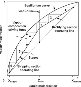
econ-Figure 2 Typical McCabe}Thiele diagram.
omical; excessive temperatures result in Rlm boiling; interaction between columns should be controlled.
8. Shipping weight and total height restrictions tend to limit the maximum number of trays or packing in one tower shell.
9. Lowering the operation pressure is a simple way to reduce energy consumption. Increasing pres-sure is the simpler way to increase capacity. 10. Lower energy consumption usually requires
higher capital costs.
McCabe
+
Thiele Diagrams
One of the best visual aids for distillation is the ubiquitous McCabe}Thiele diagram. Despite its many limitations, the diagrams show the basic rela-tionship between the equilibrium curve and the com-position proRles throughout the column. A typical McCabe}Thiele diagram is illustrated in Figure 2. Heating or cooling changes the internal vapour and liquid Sows and this effect can be seen as a shift in the slope of the operating lines in the diagram. For energy management, we are interested in seeking ways to minimize the difference (the composition driving forces) between the operating and equilibrium curves.
The absolute minimum energy expenditure will occur if external heating or cooling is applied to each stage to adjust the operating line so that it coincides with the equilibrium curve. This condition is imprac-tical, since an inRnite number of stages would be
required. The goal is to design a column with an approach as close as possible to equilibrium, but with an acceptable number of stages. A few successful designs exist that provide internal continuous cryogenic cooling in a small tray section. These types of columns that have continuous, internal heat ex-changers are called dephlegmators.
There are numerous practical applications in the industry where addingjust a few selectexternal heat-ing or coolheat-ing locations will provide a cost-effective reduction in energy.
Intermediate Heating and Cooling
Pumparounds
One of the earliest methods for saving signiRcant amounts of energy was developed for crude units. Pumparounds are used extensively in atmospheric and vacuum towers to remove heat at selected stages. Liquid is withdrawn from an intermediate product stage, externally cooled and then pumped back to the column at a higher elevation. This arrangement is shown inFigure 3. The hot liquid from the tower is used to supply heat to several sources. The remaining cooled liquid is returned to the column and used to cool the column vapour. Pumparounds have the ef-fect of shifting the operating linesat select intervals
closer to the equilibrium curve to improve energy consumption. The sub-cooled liquid provided in the pumparound reduces the cold utility requirements and size of the overhead system. The cooling tower and condensers are less expensive and thermal and wastewater pollution is reduced. The hot pum-paround liquid has the additional role of recovering heat supplied in the feed furnaces by transferring it to feed pre-heat, steam generation and heating for downstream units.
Intercondensers and Interreboilers
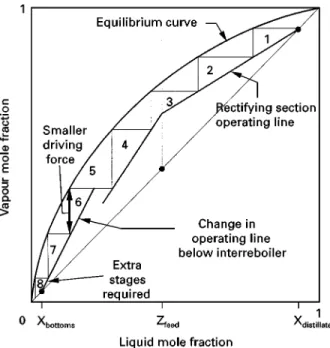
Another useful technique for reducing the utility loads is to add intermediate exchangers. Figure 4
shows the effect of adding an inter-reboiler on a McCabe}Thiele diagram. The beneRt of this modiR -cation is that thereboilerheat duty is reduced by the amount of duty used in the inter-reboiler. Since the temperature level will be less than the reboiler tem-perature, it may be possible to use a process stream for the heating. If this heat integration is feasible, then signiRcant savings of the reboiler utility, such as high pressure steam, can be achieved. The internal column
Figure 3 Pumparound section.
Figure 5 Column grand composite curve.
Figure 4 McCabe}Thiele diagram with interreboiler.
usually economical only when a few extra stages will be required. An analogous result will be obtained with an inter-condenser. The condenser utility load will be reduced, the internalSows in the stages above the condenser will be reduced, but more stages will be required. The beneRts of intermediate cooling or con-densing are particularly economical when an expen-sive refrigerant is used as the condenser cooling medium.
There are semi-rigorous calculation methods for determining how much heat can be added or removed
at a particular temperature level. One technique, which is an extension of ‘pinch’ technology, is to generate a column grand composite curve (CGCC). These curves plot the heat transferred between the vapour and liquid versus stage temperature. A typical example is shown in Figure 5. The best opportunities for using intermediate heat exchangers exist in the regions where large amounts of heat are exchanged at temperatures signiRcantly different to that of the reboiler or condenser. When deciding upon how much heat will be added or removed, one should consider the extra stages that will be required and allow for a suitable design margin for
Sexibility. If this type of region exits near the feed locations, then feed conditioning may be an option. Adding a feed exchanger will generally be less expen-sive than adding an intermediate exchanger on the column.
Feed Conditioning
The feed is introduced into the column where the temperature and composition roughly match the col-umn proRle. The feed is at higher pressure in order to
Figure 6 Prestripper column sequence.
Figure 7 Heat-pumped column.
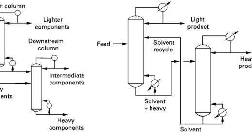
Figure 8 Extractive distillation configuration.
energy penalty will be increased condenser duty, but internal modiRcations or tower replacement may be avoided.
Prefractionation
In a multi-component column separation, the pres-ence of lighter nonkey components will limit the purity of the light key. At the top of the tower, the light key will actually be the heavier component and its composition will reach a maximum value and then decrease as it is fractionated from the lightest compo-nents. By removing these lighter non-key components from the feed in a pre-absorber, the column can now produce a higher purity product. Removing the light components from the feed reduces the Sow to the column, so that pre-absorbers can be used to unload the rectifying section of an existing column. In ana-logous fashion, the addition of a pre-stripper will unload heavy components from the stripping section of a column.Figure 6shows an illustration of a pre-stripper column arrangement. The additional feed to the last column will usually provide a modest energy saving for that column.
Heat Pumping
A signiRcant saving in condenser duty can be achieved by compressing the overhead vapour to a temperature that can be used to reboil the bottoms liquid. A typical heat-pumped column is shown in
Figure 7. The compressor is a signiRcant addition to the total capital costs. This scheme is feasible if the distillation involves a close boiling mixture where the top and bottom temperatures are not signiRcantly different. The most common industrial application is propane/propylene splitters, which require large
amounts of heating and cooling energy. A large re-duction in cooling water and wastewater products provides a large incentive to heat pump these types of columns.
Extractive and Azeotropic Distillation
Figure 9 Direct column sequence.
If the addition of a light component can alter an azeotrope, then the process is termed azeotropic dis-tillation. The entrainer often forms a new low boiling azeotrope that is relatively easy to separate from the heavier product. The entrainer is separated from the lighter product with an additional column and/or condensed to two liquid phases that are separated in a settling drum. Azeotropes are common in the specialty chemicals industry and most conRgurations are proprietary.
Extractive or azeotropic distillation should be con-sidered a last resort option. Finding a suitable solvent or entrainer that is inexpensive and relatively inert is the key to a practical design.
Column Internals Selection
The choice of internals can have impact on energy efRciency, control response and downstream equip-ment. The function of trays or packing is to promote efRcient heat and mass transfer by intimate contact-ing of the vapour and liquid. For trays, a portion of the vapour energy is expended in the form of pressure drop to produce liquid droplets and to overcome the liquid head on the tray. In contrast, the contact area in packing is mainly created by the spreading of liquid over the metal surfaces and by rivuletSow. For these reasons, the pressure drop in packing is signiRcantly less than in trays.
This becomes an important characteristic in high vacuum distillation, where the pressure and temper-ature changes dramatically from top to bottom as pressure drop increases. A tower pressure change from 50 mm Hg to 25 mm Hg will double the vol-umetricSow of vapour and will have a major impact on the tower size. The normal design pressure drop foronetray is 3}5 mm Hg, which will limit the num-ber of trays that can be used. Low pressures and temperatures in the top of the tower have an impact on the cost and performance of the condenser and vacuum system. Using lower pressure drop internals reduces the exergy losses associated with momentum and temperature difference. For these reasons, packed ns are favoured for vacuum distillations.
There also is an advantage to lowering pressure drop in a column when the overhead vapour is fed to a compressor. Changing from trays to packing during a capacity increase revamp is a convenient way to avoid compressor changes. If the pressure drop through the tower is reduced, the increase in compressor suction pressure may just compensate for the new capacity increase.
By virtue of lower pressure drop and liquid hold-up, packed columns have relatively faster response to changes inSow and composition changes. The faster
acting control of the column reduces the energy waste of recycling off-spec product.
Column Sequencing
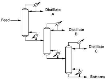
The sequencing and arrangement of columns to ob-tain multiple products has a major impact on energy and capital costs. In order to separateXamount of products, a minimum ofX!1 simple, conventional columns are required. If the products are removed as distillates, the arrangement is called a direct se-quence. The direct sequence is favoured when the distillations are at high pressure and require refriger-ation, such as oleRn production. An indirect sequence is used if the products are withdrawn as bottoms. Indirect sequencing favours lower heat consumption. In many petrochemical plant conRgurations, both se-quences are used or mixed as dictated by the many product requirements. An illustration of the direct and indirect sequence arrangement is given in
Figures 9and10.
A number of heuristics have evolved from experi-ence of sequencing columns. A few of the more com-mon guidelines are listed below:
1. Leave the most difRcult separations to the end. The binary separation of high purity products re-quires larger towers and higher energy consump-tion when non-key components are present. 2. Direct sequences are favoured when heating costs
are less than cooling costs.
3. Less energy is expended when the top and bottom productSows are about equal.
Figure 10 Indirect column sequence.
Figure 11 Distributed column sequence.
are commonly integrated with the total plant optimization to minimize overall capital costs, energy consumption and pollution reduction. Techniques such as pinch technology and exergy analysis are used to evaluate the global effect of equipment changes to arrive at the best plant design, which may not coincide with the best column design.
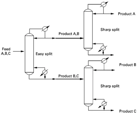
Distributed Distillation
Distributed distillation is a separation technique that minimizes the lost work due to mixing and recycling of Suids within a column. The energy consumption can be reduced by making a separation between the most volatile and least volatile components with the rest of the components distributed between the top and bottom. An easy separation between components
with the highest relative volatility will yield the min-imum boil-up and reSux for any column. This con-cept is illustrated inFigure 11. A distributed column sequence will theoretically consume less energy, but will require more columns. The energy savings have been reported to be upwards of 30%.
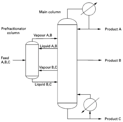
To lower the capital costs, the column can be thermally coupled as described in the Petlyuk conR g-uration shown inFigure 12. Thermal coupling is used to describe the situation when liquid from a column is used to supply reSux and vapour is used to supply boil-up to another column. Several variations of this arrangement are used to eliminate heat ex-changers in column designs. Combining the two columns together and providing a partition to form adivided wall columnreduces the capital cost. Three products can be produced from one column, one reboiler and one condenser, as compared to a conven-tional sequence that requires two columns and four exchangers. The commercial use of divided wall col-umns tends to be limited to separations with signiR -cant amounts of intermediate components.
The Future of Energy and Distillation
Figure 12 Petlyuk configuration.
versatility of distillation. Current research efforts have been evolutionary and the majority of the indus-try is reluctant to test any technology that has not been commercially proven. Therefore, even promis-ing new technology changes are slow and cautious. Many research efforts have started to combine the best features of different separation methods to save energy and capital costs. The future of distillation will always depend upon energy costs and change will occur when these costs become unac-ceptable.
See also: II/Distillation: High and Low Pressure Distilla-tion; Historical Development; Modelling and SimulaDistilla-tion; Multicomponent Distillation; Packed Columns: Design and Performance; Pilot Plant Batch Distillation; Theory of Dis-tillation; Tray Columns: Design; Vapour-Liquid Equilib-rium: Theory.
Further Reading
Dhole VR and Linhoff B (1993) Distillation column targets. Computers in Chemical Engineering17 (56): 549}560. Dodge BF (1994)Chemical Engineering Thermodynamics.
New York: McGraw-Hill.
Fonyo Z (1974) Thermodynamic analysis of rectiRcation}I. Reversible model of rectiRcation.International Chem-ical Engineer14(1): 18}27.
Kaibel G Blass E and Kohler J (1990) Thermo-dynamics}guidelines for the development of distillation column arrangements.Gas Separation and PuriTcation 4: 109}114.
Kaibel G (1992) Energy integration in thermal process-engineering. International Chemical Engineer 32 (4): 631}641.
King CJ (1971)Separation Processes. New York: McGraw-Hill.
Liebert T (1993) Distillation feed preheat } is it energy efRcient?Hydrocarbon Processing3: 37}42.
Linhoff B, Dunford H and Smith R (1983) Heat integration of distillation columns into overall process. Chemical Engineering Science38: 1175}1188.
Petterson WC and Wells TA (1977) Energy-saving schemes in distillation.Chemical Engineer(September): 78}86. Sussman MV (1980)Availability(Exergy)Analysis.
Lexin-gton, MA: Mulliken House.
Terranova BE and Westerberg AW (1989) Temper-ature}heat diagrams for complex columns. I. Inter-cooled/interheated distillation columns. Ind. Eng. Chem.Res. 28: 1374}1379.
Treybal RE (1968) Mass-Transfer Operations, 2nd edn. New York: McGraw-Hill.
US Department of Energy (1994)Assessment of Potential Energy Savings in Fluid Separation Technologies. Docu-ment DOE/ID/124763-1, December. Washington, DC: US Department of Energy.