Field Manual
No. 5-33 *FM 5-33
HEADQUARTERS DEPARTMENT OF THE ARMY Washington, DC, 11 July 1990
Terrain Analysis
PrefaceSCOPE
Terrain analysis, an integral part of the intelligence preparation of the battlefield (IPB), plays a key role in any military operation. During peacetime, terrain analysts build extensive data bases for each potential area of operations. They provide a base for all intelligence operations, tactical decisions, and tactical operations. They also sup-port the planning and execution of most other battlefield functions. Because terrain features continually undergo change on the earth’s surface, data bases must be continuously revised and updated.
PURPOSE
This field manual prescribes basic doctrine and is intended to serve as a primary source of the most current available information on terrain analysis procedures for all personnel who plan, supervise, and conduct terrain analysis. The manual discusses the impact of the terrain and the weather on operations.
USER INFORMATION
The proponent of this publication is the US Army Engineer School. Submit changes for improving the publication on DA Form 2028 (Recommended Changes to Publications and Blank Forms) to Commandant, Directorate of Training and Doctrine, US Army En-gineer School, ATTN: ATSE-TDM-P, Ft. Leonard Wood, MO 65473-6500.
Approved for public release; distribution is unlimited.
Unless otherwise stated, whenever the masculine gender is used, both men and women are included.
*This publication supersedes FM 21-33, 15 May 1978, and FM 30-10, 27 March 1972.
C1 HEADQUARTERS
CHANGE DEPARTMENTS OF THE ARMY
NO. 1 Washington, DC, 8 September 1992
Terrain Analysis 1. Change FM 5-33, 11 July 1990, as follows:
Page 10-1. Table 10-1, 2. Circles, change formulas to read:
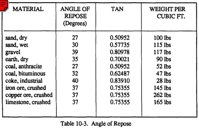
Page 10-3. Table 10-3. Change entry in last line, last column, to ’’118 lb.”
Page 10-4. To the second paragraph under the subheading “Six Functions’’add the following drawing:
2. Post these changes according to DA Pamphlet 310-13. 3. File this transmittal sheet in front of the publication.
By Order of the Secretary of the Army:
Official:
GORDON R. SULLIVAN General, United States Army
Chief of Staff
MILTON H. HAMILTON Administrative Assistant to the
Secretary of the Army 02181
DISTRIBUTION:
Active Army, USAR, and ARNG: To be distributed in accordance
PART ONE
Natural Terrain
Chapter 1SURFACE CONFIGURATION
Maneuver commanders must have accurate intelligence on the surface configura-tion of the terrain. Ravines, embankments, ditches, plowed fields, boulder fields, and rice-field dikes are typical surface configurations that influence military activities. Elevations, depressions, slope, landform type, and surface roughness are some of the terrain factors that affect movement of troops, equipment, and material.
Landforms
Landforms are the physical expression of the land surface. The principal groups of landforms are plains or plateaus, hills, and mountains. Within each of these groups are surface features of a smaller size, such as flat lowlands and valleys. Each type results from the interaction of earth processes in a region with given climate and rock conditions. A complete study of a landform includes determina-tion of its size, shape, arrangement, surface configuradetermina-tion, and reladetermina-tionship to the surrounding area.
Relief
Local relief is the difference in elevation between the points in a given area. The elevations or irregularities of a land surface are represented on graphics by contours, hypsometric tints, shading, spot elevations, and hachures.
Slope or Gradient
FM 5-33 Terrain Evaluation and Verification PART ONE surface. The actual angle is found by using trigonometric tables. The percent of slope is the number of meters of elevation per 100 meters of horizontal distance. Slope information that is available to the analyst in degrees or in ratio values may be converted to percent of slope by using a nomogram.
VEGETATION FEATURES
Plant cover can affect military tactics, decisions, and operations. Perhaps the most important is concealment. To make reliable evaluations when preparing vegetation overlays, analysts must collect data on the potential effects of vegetation on vehicular and foot movement, rover and concealment, observation, airdrops, and construction materials.
Types
The types of vegetation in an area can give an indication of the climatic conditions, soil, drainage, and water supply. Terrain analysts are interested in trees, scrubs and shrubs, grasses, and crops.
On military maps, any perennial vegetation high enough to conceal troops or thick enough to be a serious obstacle to free passage is classified as woods or brushwood. Although trees provide good cover and concealment, they can present problems to movement of armor and wheeled vehicles. Woods also slow down the movement of dismounted troops. Individual huge trees are seldom so close together that a tank cannot move between them, but the space between them is often filled by smaller trees or brush. Closely spaced trees are usually fairly small and can be pushed over by a tank; however, the resulting pileup of vegetation may stop the tank. Trees that can stop a wheeled vehicle are usually too closely spaced to bypass. The pileup effect from pushing over vegetation is greater for wheeled vehicles than for tanks.
Trees are classified as either deciduous (broadleaf) or coniferous (evergreen). With the exception of species growing in tropical areas and a few species existing intemperate climates, most broadleaf trees lose their leaves in the fall and become dormant until the early spring. Needleleaf trees do not normally lose their leaves and exhibit only small seasonal changes.
Woodlands or forests are classified according to the dominant local tree type. A forest is classified as either deciduous or coniferous if it contains at least 60 percent of that species. Wooded areas that contain less than a 60 percent mixture of either species are classified as a mixed forest.
Scrubs include a variety of trees that have had their growth stunted because of soil or climatic conditions. Shrubs comprise the undergrowth in open forests, but in arid and semiarid areas they are the dominant vegetation. Shrubs normally offer no serious obstacle to movement and provide good concealment from ground observation however, they may restrict fields of fire.
For terrain intelligence purposes, grass more than 1 meter high is considered tall. Grass often improves the trafficability of soils. Very tall grass may provide concealment for foot troops. Foot movement in savannah grasslands is slow and tiring; vehicular movement is easy; and observation from the air is easy.
Field crops constitute the predominant class of cultivated vegetation. Vine crops and orchards are common but not widespread, and tree plantations are found in relatively few areas. The size of cultivated areas ranges from paddies covering a quarter of an acre to vast wheat fields extending for thousands of acres.
In a densely populated agricultural area where all arable land is used for the crop producing the highest yield, it may be possible to predict the nature of the soils from information about the predominant crop. Rice, for example, requires fine-textured soils, while other crops generally must have firm, well-drained land. An area of orchards or plantations usually consists of rows of evenly spaced trees, showing evidence of planned planting. This can be distinguished on an aerial photograph. Usually such an area is free of underbrush and vines. Rice fields are flooded areas surrounded by low dikes or walls.
Some crops, such as grain, improve the trafficability of soils, while others, such as vineyards, present a tangled maze of poles and wires and create definite obstacles to vehicles and dismounted troops. Wheeled vehicles and some tracked vehicles are unable to cross flooded paddy fields, although they can negotiate them when the fields are drained and dry or frozen. Sown crops, such as wheat, barley, oats, and rye, will have a different impact on movement and concealment than those crops planted in furrows, because they are on a flat surface.
Photographic Texture
Texture is influenced by several variables, including crown shapes, tree spacing, and tree height. Texture interpretation as a means of identifying forest type requires knowledge of the texture often associated with each forest type. This knowledge is acquired through hands-on experience or the use of vegetation keys. With hands-on experience working with aerial imagery over along period of time and through the process of trial and error, an analyst can develop a mental catalog to relate texture in a given geographic area to a specific forest type.
Vegetation keys have been developed through the same trial and error process but have been documented and are available in the literature. They can be very useful in certain instances (see Chapter 3 for examples). However, one must remember that background knowledge of the area of interest is essential and most keys are specific to tree species, geographic area, time of year, film type, and photoscale. When using color or color infrared film, tone is often referred to as hue and is represented as shades of the color image.
Photographic Tone
FM 5-33 Terrain Evaluation and Verification PART ONE
SOIL FEATURES
Since soils vary in their ability to bear weight, their ability to withstand vehicle passes, and their ease of digging, military planners rely heavily on soil analyses. Soil type, drainage characteristics, and moisture content affect road construction, material location, and trafficability determination. The soil factor overlay breaks down the most probable soil types, characteristics, and distribution.
Describing and classifying soil normally requires exhaustive field sampling and the expertise of soil scientists. Terrain analysts, however, can produce acceptable soil factor overlays by examining maps, other factor overlays, aerial photographs, lab analyses, boring logs, and literature. The reliability of the resulting soil factor overlays will vary with the reliability of the sources used and the analyst’s ability to correlate and combine the information correctly.
Determining whether a particular soil will support vehicle passage or the con-struction of roads and airfields is just a part of the terrain analyst’s job. Since analysts also provide information on construction materials associated with roads and airfields, they need a variety of evaluation methods and a good working knowledge of the physical properties of soil.
Type Determination
For field identification and classification, soils may be grouped into five principal types: gravel, sand, silt, clay, and organic matter. These types seldom exist separately but are found in mixtures of various proportions, each contributing its characteristics to the mixture. Some soils may gain strength under traffic while others lose it.
Gravel is angular to rounded, bulky rock particles ranging in size from about 0.6 to 7.6 cm (¼ to 3 inches) in diameter. It is classified as coarse or fine; well or poorly graded; and angular, flat, or rounded. Next to solid bedrock, well-graded and compacted gravel is the most stable natural foundation material. Weather has little or no effect on its trafficability. It offers excellent traction for tracked vehicles; however, if not mixed with other soil, the loose particles may roll under pressure, hampering the movement of wheeled vehicles.
Sand consists of rock grains from shut 0.6 cm (¼ inch) and smaller. It is classified as coarse, medium, or fine, and is angular or rounded. Well-graded angular sand is desirable for concrete aggregate and for foundation material. It is easy to drain and ordinarily not affected by frost action or moisture. Analysts must be careful, however, to distinguish between a fine sand and silt. When wet enough to become compacted or when mixed with clay, sand provides excellent traf-fixability. Very dry, loose sand is art obstacle to vehicles, particularly on slopes. Under wet conditions, remoldable sands react to traffic as to fine-gained soils. They feel somewhat plastic rather than gritty when rolled between the fingers.
Terrain Evaluation and Verification FM 5-33 ground water or seepage is present, silt exposed to frost action is subject to ice accumulation and consequent heaving.
Clay generally consists of microscopic particles. Its plasticity and adhesiveness are outstanding characterisitcs. Depending on mineral composition and proportion of coarser grains, clays vary from lean (low plasticity) to fat (high plasticity). Many clays which are brittle or stiff in their undisturbed state become soft and plastic when worked. When thoroughly dry, clay provides a hard surface with excellent trafficability; however, it is seldom dry except in arid climates. It absorbs water very slowly but takes a long time to dry and is very sticky and slippery. Slopes with a clay surface are difficult or impassable, and deep ruts form rapidly on level ground. A combination of silt and clay makes a particularly poor surface when wet.
Chemically deposited and organic sediments are classified on the basis of mode and source of sedimentations. The identification of highly organic soil is relatively easy; it contains partially decayed grass, twigs, leaves, and so forth, and has a characteristic dark brown to black color, a spongy fed, and fibrous texture.
Classification
The terrain analyst uses the field classification technique to determine if the soil is fine or coarse or if it is remoldable sand. Usually the first two steps will determine the grain. If it is squeezed and rolled between the fingertips, fine-grained plastic soil will feel soft and smooth and should produce a ribbon or thread. Remoldable sands will feel coarser and more abrasive than a fine-grained material.
Unified Soil Classification System (USCS) The Unified Soil Classification System uses a system of two-letter abbreviations to describe the soil. The primary letter identifies the predominant soil fraction. The secondary letter further describes the characteristics of the predominant soil fraction. The percent of gravel, sand, and frees provides the information necessary to choose the primary letter. See Figure 1-1.
Physical Tests
Before analysts classify soil, they must make four physical tests: gradation, liquid limit, plastic limit, and odor test.
Gradation, or grain-size distribution of a soil, is determined by a sieve analysis. A sieve analysis is the separation of soil into its fractions. It is made to determine gradation of material retained on a No. 200 sieve. It indicates whether a soil is well or poorly graded, and it will show the percentage of fines present. The sieve analysis may be performed directly on soils that may be readily separated from the coarser particles.
Sieves that military engineers commonly use have square openings and are designated as 2-, 1½-, 1-, ¾-, and ¼- inch sieves. They also use the US standard numbers 4, 10, 20, 40, 60, 100, and 200 sieves. See Figure 1-2 for an example of a sieve analysis.
PRIMARY LETTERS G--Gravel
FM 5-33 Terrain Evaluation and Verification PART ONE S--Sand
C--Clay (Used only with fine-grained soil with 50% tines or greater) M--Silt
O--Organic SECONDARY LETTERS
W--Well graded (Used to describe sands containing less than 12% fines) P--Poor graded
M--Silty Fines (Used with sands and gravels containing less than 5% but more than or equal to 50% frees)
C--Clay-based Pines
L--Low Compressibility (Used to describe fine-grained soils (silts, clays, organics)
H--High Compressibility
As soil becomes more moist, it transforms from a plastic to a liquid state. The liquid limit is the moisture content at which a soil will just begin to flow when jarred slightly. In conjunction with the plastic limit, it is valuable in proper identification and classification of fine-grained soils. The liquid limit is usually expressed as a whole number and is obtained by performing the Atterberg liquid limit test, which is outlined in TM 5-530.
The plastic limit is the moisture content at which cohesive soil passes from a semisolid to a plastic state. A soil or soil fraction is called plastic if, at some water
Terrain Evaluation and Verification FM 5-33
content, it can be rolled out into thin threads. The moisture content ranges between a soil sample’s liquid and plastic limits. The larger the plasticity index, the more plastic the soil (PI = LL - PL). The percent of moisture content, by weight, at which a 1/8-inch diameter thread begins to crumble is expressed as a whole number when
Note: Gravels will be retained at ¼ - to 2-inch sieves, sands at Numbers 4-100; all fines will be retained at the No. 200 sieve, allowing estimation of percentages of soil categories.
recorded
FM 5-33 Terrain Evaluation and Verification PART ONE Since practically all fine-grained soils contain some clay, most of them will exhibit some amount of plasticity. Soil plasticity is determined by measuring the different states a plastic soil undergoes with changing moisture content. When a fine-grained soil or remoldable sand sample is rolled between two flat surfaces or between one’s thumb and forefinger, it forms a thread. Highly plastic and nonplas-tic soils break into short lengths or cannot be formed into ribbons. In the field, analysts can examine the shape and mineral compositions of coarse-grained soil by spreading a dry sample on a flat surface, separating the gravel and frees as much as possible, and estimating the percentages of each. TM 5-530 gives further information.
Organic soils of the OL and OH groups usually have a distinct odor, which can be used to aid in identification. This color is especially apparent in fresh samples. It is gradually reduced when exposed to air, but can be brought out again by heating a wet sample.
Field Identification
Normally, laboratory equipment will not be available in the field, but analysts can estimate and tentatively classify without tests. Classifications made under stricter conditions will be more accurate. We classify soils by particle size distribution. Where these soil types occur and the amount of area they cover often determine the suitability of an area for military operations. In general, we prefer coarse-grained soils for construction and cross-country movements.
Well-graded and poorly-graded soils can usually be distinguished by comparing the sizes. Poorly-graded soils, however, are more difficult to classify because they lack one size particle. Principal aids to soil identification and classification are the shaking test, the dry strength or breaking test, and gully analysis.
Analysts performing the shaking test will alternately shake a wet portion of soil in the palm of the hand and squeeze between the fingers. Atypical inorganic silt will become livery, show free water to disappear from siIt soil, and cause the sample to stiffen and crumble under increasing finger pressure. If the water content is just right, shaking the broken pieces will cause them to liquefy and flow together. The portion will change its consistency and the water on the surface will appear or disappear at a rapid, sluggish, slow, or no-reaction speed. A rapid reaction to this test is typical for a nonplastic, uniform fine sand, inorganic silt, or diatomaceous (algae-based) earths. A sluggish reaction indicates slightly plastic inorganic and organic silts, or very silty clays. An extremely slow or no reaction to the shaking test is typical for all clays that plot above the A-line on the plasticity chart as well as for highly plastic organic clays.
The dry strength test readily distinguishes between plastic clays and nonplastic silts or fine sands. Analysts perform the dry strength or breaking test only on a smaIl portion of soil, about ½-inch thick and 1½ inches in diameter, that passes the Number 40 sieve. They prepare this by molding a portion of wet plastic soil into the size and shape desired and allowing it to air (NOT oven) dry. After the sample is thoroughly dry, they will attempt to break the soil using their thumbs and forefingers. If it breaks, they will try to powder it by rubbing the particles together. Typical reactions obtained in this test for various types of soil
PART ONE
Very highly plastic soil, or very high dry strength. Samples cannot be broken or powdered by finger pressure.
Highly plastic soil, or high dry strength. Samples will break with great effort, but they cannot be powdered.
Medium plastic soil, or medium dry strength. Samples will break and powder with some effort.
Slightly plastic soil, or low dry strength. Samples will break and powder easily.
Nonplastic soil, or very little or no dry strength. Samples crumble and powder on being picked up.
Gullies, sometimes called head water channels, result from erosion caused by water runoff. They develop in places where water cannot easily filter into the ground; therefore, it collects and flows in rivulets across the land surface. Gully analysis can be of great assistance in determining soil types, since these rivulets often take the shape peculiar to the material over which they flow. Since fine-grained silts and clays are relatively impervious soils, many gullies develop on their surfaces. Sands and gravels are rather permeable, and few or no gullies form.
Other factors that govern the extent of gully formation in an area are climate, vegetation, ground slope, end gradient of individual gullies. Gradient is more important than intensity, or number, of gullies in revealing soil conditions. The types of gullies that may be formed in various soil types
are--Gullies in clay. They have a long, uniform, gentle gradient and are smoothly rounded. Clay soils are impervious and cohesive and often have a well-developed gully system.
Gullies in silt (primarily loess). They take the form of a U and have steep sides and generally flat bottoms. The gradient is steep at the head of the gully but becomes more gentle a short distance away.
Gullies in sand-clay. They are similar to gullies in silts but are more U-shaped, with a rounded rather than flat bottom. The gradient is nearly vertical at the head of the gully but levels off rapidly to a very gentle slope.
Gullies in gravel, sand, or well-graded mixtures with some clays. They are usually well-defined, short, straight notches (ditches). The cross sec-tion is a sharp V with a uniform gradient. The steeper gradients are as-sociated with the coarser materials. See Figure 1-3.
WATER FEATURES
FM 5-33 Terrain Evaluation and Verification PART ONE
Quantity
Water quantity depends on the climate of the area. Plains, hills, and vegetation are good indicators of water sources.
Large springs are the best sources of water in karstic plains and plateaus. Wells may produce large amounts if they tap underground streams. Shallow wells in low-lying lava plains normally produce large quantities of ground water. In lava uplands, water is more difficult to find, wells are harder to develop, and careful prospecting is necessary to obtain adequate supplies. In wells near the seacoast, excessive withdrawal of freshwater may lower the water table, allowing infiltration of saltwater that ruins the well and the surrounding aquifer.
Springs and wells near the base of volcanic cones may yield fair quantities of water, but elsewhere in volcanic cones the ground water is too far below the surface for drilling to be practicable. Plains and plateaus in arid climates generally yield small, highly mineralized quantities of ground water. In semiarid climates, follow-ing a severe drought, an apparently dry streambed frequently may yield consider-able amounts of excellent subsurface water. Ground water is abundant in the plains of humid tropical regions, but it is usually polluted. In arctic and subarctic plains, wells and springs fed by ground water above the permafrost are dependable only in summer; some of the sources freeze in winter, and subterranean channels and outlets may shift in location. Wells that penetrate aquifers within or below the permafrost are good sources of perennial supply.
Adequate supplies of ground water are hard to obtain in hills and mountains composed of gneiss, granite, and granite-like rocks. They may contain springs and shallow wells that will yield water in small amounts.
Tree species can also indicate local ground water table presence. Deciduous trees tend to have far-reaching root systems indicating a water table close to the ground surface. Coniferous trees tend to have deep root systems, which depict the ground water table as being farther away from the ground surface. In desert environments, vegetation is scant and specialized to withstand the stress of desert life. Vegetation type is dependent on the water table of that location. Palm trees indicate water within 2 or 3 feet, salt grass indicates water within 6 feet, and cottonwood and willow bees indicate water within 10 to 12 feet. The common sage, greasewood, and cactus do not indicate water levels.
Quality
Quality will vary according to the source and the season, the kind and amount of bacteria, and the presence of dissolved matter or sediment. Color, turbidity, odor, taste, mineral content, and contamination determine the quality of water. Brackish water is found in many regions throughout the world but most frequently along sea coasts or as ground water in arid or semiarid climates.
Contamination
Potable water is free from disease-causing organisms and excessive amounts of mineral and organic matter, toxic chemicals, and radioactivity. Although surface water is ordinarily more contaminated than other sources, it is commonly selected for use in the field because it is more accessible in the quantity required. Ground water is usually less contaminated than surface water and is, therefore, a more desirable water source. However, the use of ground water by combat units is usually limited unless existing wells are available. Rain, melted snow, or melted ice may be used in special instances where neither surface nor ground water is available. Water from these sources must be disinfected before drinking.
Pollution
Water may be contaminated but not polluted. Streams in inhabited regions are commonly polluted, with the sediment greatest during flood stages. Streams fed by lakes and springs with a uniform flow are usually clear and vary less in quality than do those fed mainly by surface runoff. Generally, the quality of water in large lakes is excellent, with the purity increasing with the distance from the shore. Very shallow lakes and small ponds are usually polluted.
Porosity and Permeability
FM 5-33 Terrain Evaluation and Verification PART ONE Drainage
Surface
Most military problems involving surface water arise because stream drainage conditions vary not only from place to place but seasonally as well. Military planners are concerned with the flow and channel characteristics of surface waters and their effect on military operations. The water constitutes obstacles to cross-country movement or, when sufficiently frozen, it may provide movement. They also determine the types of equipment to be used in an area.
Drainage data on all of the surface water features is significant to any aspect of military operations. Commanders must know the width and depth of streams and canals; the velocity and discharge of streams; which areas are subject to flooding, or are permanently wet, densely ditched, or canalized; the location of dams; and any other drainage feature that may be significant.
Although surface drainage is considered a standard product, subsurface drainage is not. Potential ground water indicators include the following:
Crop irrigation Karst topography Snowmelt patterns Wetlands Vegetation Springs Soil moisture Surface water Wells/Qanats
Built-up areas (local municipalities and populus)
Surface water resources are generally more accessible and adequate in plains and plateaus than in mountains. Large amounts of good quality water can normally be obtained in coastal areas, valleys, or alluvial and glacial plains. Although large quantities are available in delta plains, the water may be brackish or salty. Water supplies are scarce on lacustrine, loess, volcanic, and karst plains. In the plains of arid regions, water usually cannot be obtained in quantities required by a modem army; much that is available is highly mineralized. In the plains and plateaus of humid tropical regions, surface water is abundant but is generally polluted and requires treatment. Perennial surface water supplies are difficult to obtain in arctic regions; in summer it is abundant but often polluted.
Subsurface
Ground water, or subsurface drainage, is obtained without difficulty from uncon-solidated or poorly conuncon-solidated materials in alluvial valleys and plains, streams and coastal terraces, glacial outwash plains, and alluvial basins in mountainous regions. Areas of sedimentary and permeable igneous rocks may have fair to excellent aquifers, although they do not usually provide as much ground water as areas composed of unconsolidated materials. Large amounts of good-quality ground water may be obtained at shallow depths from the alluvial plains of valleys and coasts and in somewhat greater depths in their terraces. Aquifers underlying the surface of inland sedimentary plains and basins also provide adequate amounts of water. Abundant quantities of good-quality water generally can be obtained from shallow to deep wells in glacial plains. In loess plains and plateaus, small
PART ONE FM 5-33 amounts of water may be secured from shallow wells, but these supplies are apt to fluctuate seasonally. Well water is usually clear and low in organic impurity but may be high in dissolved mineral content.
Patterns
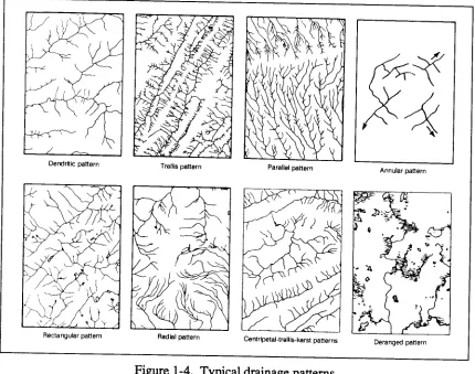
The pattern of stream erosion usually gives an indication of rock structure and composition and an indication of whether the region is underlined by one or several rock types. The pattern can be dendritic, trellis, radial, annular, parallel, or rectangular.
The dendritic drainage pattern is a tree-like pattern composed of branching tributaries to a main stream, characteristic of essentially flat-lying and homogeneous rocks. This pattern implies that the area was originally flat and is composed of relatively uniform materials. Dendritic drainage is also typical of glacial till, tidal marshes, and localized areas in sandy coastal plains. The dif-ference in texture or density of a dendritic pattern may help identify surface materials and organic areas.
In a trellis pattern, the mainstream runs parallel, and small streams flow and join at right angles. This pattern is found in areas where sedimentary or metamorphic rocks have been folded.
In a radial pattern, streams flow outward from a high central area. This pattern is found on domes, volcanic cones, and round hills. However, the sides of a dome or volcano might have a radial drainage system while the pattern inside a volcanic cone might be centripetal, converging toward the center of the depression.
The annular pattern is a modified form of the radial drainage system, found where sedimentary rocks are upturned by a dome structure. In this pattern, streams circle around a high central area. The granitic dome drainage channels may follow a circular path around the base of the dome when it is surrounded by tilted beds.
In the parallel pattern, major streams flow side by side in the direction of the regional slope. Parallel streams are indicative of gently dipping beds or uniformly sloping topography. The greater the slope, the more nearly parallel the drainage and the straighter the flow. Local areas of lava flows often have parallel drainage, even though the regional pattern may be radial. Alluvial fans may also exhibit parallel drainage, but the pattern may be locally influenced by faults or jointing. Coastal plains, because of their slope toward the sea, develop parallel drainage overboard regions.
FM 5-33 Terrain Evaluation and Verification PART ONE
Density
A determination of the density of the drainage pattern, or the number of streams in a precise area, is very beneficial. The nature of the drainage pattern in an area will provide a strong indicator of the particle size of the soils that have developed. Surface sediments have good internal drainage. Sandstone, for example, due to its porosity and permeability, has good internal drainage. Water can usually percolate down through the soil and underlying reck, and the surface runoff will beat a minimum. The texture or density of the drainage pattern that develops on sandstone will be coarse.
A porous reek is not necessarily permeable. Clay, for example, contains up to 90 percent water arid is very porous but is not permeable because of the nature of its flat-lying particles.
Sands and gravels are usually both porous and permeable, depending on sorting. When precipitation occurs, some of the water can percolate down through the sediment.
[image:18.612.49.479.65.404.2]Shale is a relatively impermeable reek and has poor internal drainage. Surface runoff will be at a maximum, and erosion will often be intense. The texture or density of the drainage pattern that develops on shale will be fine-textured. See Figure 1-4.
OBSTACLES
Classification
An obstacle is any natural or man-made terrain feature that slows, diverts, or stops the movement of personnel or vehicles. Obstacles are classified as natural, such as escarpments, or man-made, such as built-up areas and cemeteries. They are further categorized as existing-present natural or as man-made terrain features that will limit mobility or as reinforced-existing features that man has enhanced to use as obstacles, such as gentle slopes reinforced by tank ditches, pikes, or revetments that limit mobility of maneuver units.
For classification purposes, obstacles must beat least 1.5 meters high and 250 meters long and have a slope greater than 45 percent (that which military vehicles are unable to travel). Obstacles that will be delineated should be in areas where they are of primary importance for the diversion of crosscountry movement. Obstacles include escarpments, embankments, road cuts and fills, depressions, fences, walls, hedgerows, and moats.
An obstacle factor overlay portrays linear terrain features that form natural obstacles not normally identifiable on a topographic map. Obstacles located in areas of dense forest, on steep slopes (greater than 45 percent), or within the gap width of streams normally will not be shown on the obstacle overlay. Hydrologic obstacles such as drainage ditches, channelized streams, and water banks are shown on the surface drainage overlay.
Identification
Escarpments are terrain features similar to cliffs and ridges and appear on aerial photographs as sharp breaks in the slope separating near level or gently sloping surfaces. They are hazardous to both troop and vehicle movement due to the sharp drop in the land typical of cliffs and ridges. Embankments are artificial structures, usually of earth or gravel, constructed above natural ground surfaces such as dikes, levees, and seawalls. Escarpments and embankments are tactically significant because explosive devices can make the road, railroad, or cross-country route impassable and because they can be used as channelization factors. This is especially true if the bypass capability is restrictive to the state of the ground.
Railroad and road cuts and falls restrict military movement. Cuts are thorough-fares or passages constructed through high areas. Fills are surfaces that have been built up or raised to bring a low area up to the same level as the surrounding surfaces. Depressions are low points or sinkholes surrounded by higher ground. They usually have slopes equal to or greater than 45 percent, which will impede movement across the terrain. Pits, quarries, and sinkholes are typical examples of depressions.
FM 5-33 Terrain Evaluation and Verification PART ONE European vineyards offer an excellent example of obstacles, due to the wet state of the ground and the wire used to support crop growth. Combined with the existing terrain, vineyards cause extreme difficulty in cross-country mobility.
Finally, moats are landforms that appear on photos as wide trenches or ditches which usually surround a structure or prominent feature and are inaccessible to vehicles. Moats are generally restricted to the British or European areas. Preliminary identification can be made by referring to the map legend on a topographic map.
PART ONE FM 5-33
Man-Made Features
Chapter 2URBAN AREAS
Urban-area intelligence is important in planning tactical and strategical opera-tions, targeting for nuclear or air attack, and planning logistical support for operations. Knowledge of characteristics in urban areas may also be important in civil affairs, intelligence, and counterintelligence operations. Although informa-tion is frequently accessible, the amount of detail required necessitates a substantial collection effort.
The first aspect of urban intelligence includes geographic location, relative economic and political importance of urban areas in the national structure, and physical dimensions such as street shapes. The six street patterns are rectangular, radial, concentric, contour conforming, medieval irregular, and planned irregular (in the new residential suburbs of some countries).
The second aspect includes physical composition, vulnerability, accessibility, productive capacity, and military resources of individual urban areas. Urban areas are significant as military objectives or targets and as bases of operations. They may be one or a combination of power centers (political, economic, military); industrial production centers; service centers; transportation centers; population centers; service centers (distribution points for fuels, power, water, raw materials, food, manufactured goods); or cultural and scientific centers (seats of thought and learning, and focal points of modem technological developments).
Buildings can provide numerous concealed positions for the infantry. Armored vehicles can find isolated positions under archways or inside small industrial or commercial structures. Thick masonry, stone, or brick walls offer excellent protec-tion from direct fire, and ceilings for individual fire. Cover and concealment can also be provided by the percentage of roof coverage. For detailed information, see FM 90-10.
FM 5-33 Terrain Evaluation and Verification PART ONE and the third number is the type of structure. If this number or its subdivisions are not needed in particular overlays, the number will be followed by zeros.
The industrial category (code 100) consists of the area and facilities that include the buildings used by those establishments engaged in the extraction, processing, and production of intermediate and finished products or raw materials, The two plant types in industrial areas are heavy manufacturing and medium and light manufacturing. Heavy-manufacturing plants require distinctive structures, such as blast furnaces, that could be readily recognized, while medium and light plants are housed in general loft buildings from which machinery could be removed. The specific type of medium-or light-manufacturing plant is not usually apparent from the type of building.
The transportation category (code 200) consists of the area and facilities used in moving materials and people on land. Features include railroads, roads, road interchanges, bridges, bridge structures, and conduits.
The commercial/recreational category (code 300) consists of the area and build-ings where the major business activities and recreational facilities comprise the congested commercial core of a city. It includes retail and wholesale establishments, financial institutions, office buildings, and hotels. Modem multistory office buildings are typical of commercial sections of large cities. More than one commercial area may exist, particularly in cities where a number of towns have merged. Recreational activities, such as amusement parks and stadiums, may also be present.
Residential areas of a city (code 400) consist of the area and associated buildings where civilians live. They include many types of dwelling structures. Buildings vary from one and two-story single family dwellings to multistory apartment houses and may be built of any materials available locally. Types and sizes of residential areas often indicate the number of people and the varying living standards throughout the city.
Communication facilities (code 500) transmit information from place to place. This category includes telephone, telegraph, and radio facilities, as well as other electronic features such as power line pylons and structures. These facilities include communication towers and buildings, as well as power transmission, observation, microwave, television, and radio towers.
The governmental and institutional category (code 600) consists of the area and facilities, primarily buildings, that constitute the seat of legal, administrative, or other governmental functions of a country or political subdivision. This category includes those buildings serving as public service institutions, such as universities, churches, and hospitals. Governmental and institutional areas may include buildi-ngs such as the capital; administrative centers such as ministries, departments, courts, legislative buildings, embassies, and police headquarters; educational, cultural, and scientific institutions such as schools, hospitals, universities, libraries, museums, theaters, research institutions and laboratories; and religious and historic structures such as churches, monuments, and shrines.
nonmilitary goods and personnel by sea and air. Military areas usually include transportation, billeting, storage, airfields, and administration facilities. Since these are of strategic and tactical importance, they require as accurate a description as possible for urban-area intelligence.
The storage category (code 800) consists of the area and facilities used for holding or handling liquids or gases, bulk solids, and finished products. Examples are cylindrical and spherical storage tanks; closed storage such as silos and grain bins; open storage such as vehicle, ship, and aircraft storage areas and storage mounds such as coal or minerals.
The landforms, vegetation, and miscellaneous features category (code 900) describes the surface landscape characteristics or natural scenery features such as levees, walls, and fences. It includes beaches, recreation areas, farms, wooded areas, swamps, and vacant land. Extensive open areas within the city may be valuable military assets, particularly if they have roads and railroad lines nearby as well as access to electric and water supply facilities. Open areas on the outskirts of cities arc the most immediately available land for military use. Features include snow or ice areas, vegetation such as orchards and vineyards, agricultural areas, and surface features such as embankments, fences, and cliffs.
TRANSPORTATION
Analysts preparing terrain studies must carefully evaluate all transportation facilities to determine their effect on proposed operations. Analysts may recom-mend destroying certain facilities or retaining them for future use. The entire transportation network must be considered in planning large-scale operations. An area with a dense transportation network, for example, is favorable for major offensives. Networks that are criss-crossed by canals and railroads and possess few roads will limit the use of wheeled vehicles and the maneuver of armor and motorized infantry.
The transportation facilities of an area consist of all highways, railways, and waterways over which troops or supplies can be moved. The importance of each area depends on the nature of the military operation involved. An army’s ability to carry out its mission depends greatly on its transportation capabilities and facilities.
Highways Features
Military interest in highway intelligence of a given area or country covers all physical characteristics of the existing road, track, and trail system. All associated structures and facilities necessary for movement and for protection of the routes, such as bridges, ferries, tunnels, and fords, are integral parts of the highway system. Planners must know where new routes will be needed to support an operation.
Road widths are given in meters. Measurements indicate the minimum width of the traveled way. Each road segment between intersections is assigned a width value, and that number is placed parallel to the road segment.
FM 5-33 Terrain Evaluation and Verification PART ONE
bombardment. Planners must avoid maintaining unnecessary routes and must hold construction of new routes to a minimum.
Road Classification
Five road classifications are recognized on 1:50,000 scale topographic maps. They are all-weather, hard-surface dual/divided highway; all-weather, hard- sur-face highway; all-weather, loose-sursur-face highway; fair-weather, loose-sursur-face highway; and cart track.
All-weather, hard-surface, dual/divided highways normally have waterproof surfaces paved with concrete, bituminous surfacing, brick, or paving stone and are only slightly affected by precipitation or temperature changes. The route is never closed to traffic by weather conditions other than temporary snow or flood blockage. Photo interpretation keys include:
Traveled portion of roadway is fairly straight. Even curves are present.
Road width is uniform with easily seen parallel sides.
Photo tint of mad surface is an even color and varies from dark gray to white.
Absence of ruts or holes on traveled portion of the roadway.
All-weather, hard-surface highways have waterproof surfaces of concrete, bitumen, brick, or paving stone and are only slightly affected by rain, frost, thaw, and heat. They are passable throughout the year to a volume of traffic never appreciably less than its maximum dry-weather capacity. They are never closed by weather conditions other than temporary snow or flood blockage. Photo interpretation keys are similar to those for the dual or divided highway.
smoothed earth with an oil coating. The roads are kept open in bad weather to a volume of traffic considerably less than its maximum dry-weather capacity. Traf-fic may be halted for short periods of time. Heavy use during adverse weather conditions may cause complete collapse. Photo interpretation keys include:
Sharp or irregular curves are present. Roadway meanders to avoid steep slopes.
Gravel or crushed rock appears a uniform light gray except for low spots that collect water and appear in dark tones.
Ruts and stones give the roadway a mottled appearance.
Roadway edges and shoulders are not clean, sharp lines; sometimes, they are very difficult to determine.
Fair-weather, loose-surface highways are constructed of natural or stabilized soil, sand clay, shell, cinders, or disintegrated granite or rock. They include logging roads, abandoned roads, and corduroy roads which become quickly impassable in bad weather. Photo interpretation keys are similar to those for the all-weather, loose-surface highway except for less visible maintenance and narrower road widths at stream crossings.
Cart tracks are natural traveled ways including caravan routes and winter roads. They are not wide enough to accommodate four-wheeled military vehicles. Photo interpretation keys include
Irregular turns and bends. Traveled roadway width varies. Apparent lack of direction.
Roadway detours around wet terrain. Railroads
Railways are a highly desirable adjunct to extended military operations. Their capabilities are of primary concern and are the subject of continuing studies by personnel at the highest levels.
Railroads include all fixed property belonging to a line, such as land, permanent way, and facilities necessary for the movement of traffic and protection of the permanent way. They include bridges, tunnels, snowsheds, galleries, ferries, and other structures.
Commanders need information on physical characteristics to determine railway capacities and maintenance or rehabilitation requirements. Railway intelligence covers all physical characteristics of the existing system and all available informa-tion pertaining to development, construcinforma-tion, and maintenance. Physical charac-teristics describe the railroad and its critical features and component parts such as roadbed, ballast, track, rails, and horizontal and vertical alignment.
Identification Keys
FM 5-33 Terrain Evaluation and Verification PART ONE
Gradients are as level as possible and seldom exceed more than three or four percent, while roads often have steep grades. In order to keep gradients at a minimum, many cuts and fills exist along the right-of-way, especially in rolling or broken terrain, while roads run up and down hills with fewer cuts and fills.
Few houses are found along railways. Highways and railroads cross each other in such a manner that no interchange of traffic is possible. Grade crossings have distinct intersection angles, and overpasses and underpasses are obvious.
narrow. Wide gages are 5 feet or wider. They are mostly used by Russian, Finnish, and Spanish lines. Standard gages are 4 feet, 8½ inches. They are used for main and branch lines in the United States and the rest of Europe. Narrow gages are less than standard. Their use is somewhat limited to and usually found in mountainous, industrial, logging, and coastal defense areas and in mines and supply dumps. In South and Central America, the one-meter gage is found in many places; however, many of the countries are now adopting the standard gage because they import US-made rolling stock. See Figure 2-2.
Fixed Installations
Classification (marshaling) yards are used to sort freight cars. They are identified by a large group of parallel tracks with a restricted (one-or two- track) entrance and exit called a choke point. Active classification yards include numerous freight cars and small switch engines. Two or more classification yards are frequently found next to each other, with their entrances through a choke point. If this choke point is higher than either classification yard, it is known as a hump. Also, one yard is often placed slightly higher than the neighboring yard to allow cars to coast out of one yard through the choke point into a previously selected track of the other yard.
Service yards are normally found in or near marshaling yards and can be identified by the presence of roundhouses, turntables, service facilities, and car repair shops. Roundhouses are used for light repair and storage of locomotives. The number of roof vents on top of the roundhouse indicates the capacity of the roundhouse. Turntables are used for turning the engines around. Service facilities include coal towers, water towers, and coal piles. Car-repair shops normally appear as long, low buildings straddling one or more tracks, with cars awaiting repairs on sidings adjacent to the buildings.
Freight or loading yards are identified by loading platforms, freight stations, warehouses, and access to other means of transportation. Special loading stations are identified by grain elevators, coal and ore bins, oil storage tanks, and livestock pens with loading ramps.
Passenger stations vary from small rural depots or suburban stations to large stations and terminals. Small stations usually do not have loading docks and may not have parking areas for automobiles or trucks. They are located close to a track, and shelters may cover waiting platforms if more than two tracks pass the station. Large stations are identified by a large number of tracks leading into or past a large building that houses waiting rooms, ticket offices, and other passenger facilities. The track or boarding area is normally covered.
FM 5-33 Terrain Evaluation and Verification PART ONE
FM 5-33 Rolling Stock
Locomotives. Locomotives vary greatly, from small switch engines 24 to 30 feet long m mainline passenger and freight locomotives 35 to 50 feet long. Locomo-tives longer than 50 feet are used for special purposes such as mountain climbing. Locomotives may be steam, electric, diesel, or diesel-electric. Steam locomotives are easily identified by smoke and stream around an operating locomotive, a smokestack, and a fuel tender attached just behind the locomotive. Electric locomotives have no fuel tender or smokestack and may be identified by overhead antennae if they receive their power from overhead lines. The lines may be evidenced by the shadows their support poles cast. Diesel locomotives lack a fuel tender and are usually identified by their streamlined appearance.
Freight cars. The boxcar is the most frequently found freight rolling stock, recognized by its rectanglar shape and little roof detail. The round-topped freight car differs only in its top. These cars average 40 to 45 feet in length in the US, 25 feet in Europe. Other freight cars are the gondola and hopper cars, which are used for coal, ore, and other bulky material or large freight that cannot be loaded into a boxcar. Shape and shadow aid in identification. Refrigerator, stock, and automobile cars are so close in appearance to boxcars that low-level obliques arc usually necessary to distinguish them. Cabooses, not always found on foreign railroads, appear as small cars attached to the end of freight trains, usually with a visible cupola.
Passenger cars. For identification purposes, the outstanding characteristic of passenger cars is their length, especially when compared with freight cars. They vary from 50 to 80 feet. Normally, it is not possible to distinguish a coach from a sleeping or dining car.
Special Equipment. Railroads have a variety of special equipment in their rolling stock. The railcar is a self-contained unit with its own power plant as well as space for passengers or mail and baggage or all three. Cranes, snowplows, and drop-center flatcars are sometimes present on rolling stock.
Railheads
Railheads are points of supply transfer from railroads to other transportation and are generally found in small towns or cities where sidings and storage space already exist. Characteristics of a railhead are spurs and sidings from a main line; a road net, including narrow gage railroads, leading away from the area; piles of materials stacked near the track trucks or wagons or both, either without order or organized into convoys or trains; and temporary dwellings, such as tents or Quonset huts, for housing troops guarding and handling supplies.
End Points
System. A railroad system is a network of railroads operated by a single management entity, government or corporate. System end points are the points where a railroad system begins, ends, or changes identification. There may be no system end points within many map sheets, but system end points will always coincide with route and segment end points.
FM 5-33 Terrain Evaluation and Verification PART ONE may often be convenient or appropriate for the analyst to select others. The route will be identified on the factor overlay by abbreviations of the two endpoints placed in parentheses. There may be no route end points within the area of a 1:50,000 factor overlay. Route end points always coincide with segment end points and may coincide with system end points. Kilometer distances are always measured from route end points.
Segment. A segment is the portion of a route characterized by uniform load-bear-ing, traffic capacity, and operating characteristics. Analysts will number segments sequentially along a route within a map sheet, starting at the segment nearest the zero kilometer point. End points of segments are defined by nodes along the route, at which anyone of the following conditions occurs:
A change in the number of tracks (points where passing tracks or sidings start or end do not constitute nodes).
A change in the gage of the track. A route or system terminal.
The point where the route crosses the neat line of the factor overlay. A terminal or junction where traffic may be diverted onto another route. A change in the type of construction such that the load-bearing capacity, speed or traffic capacity is altered.
A point where electrification starts, ends, or changes method of power transfer.
A point where a change in traffic control methods occurs, such as intern-ational boundary crossings.
Number of Tracks
Analysts indicate the number of tracks for single- and double-track lines by the number of ticks used with the gage symbol. Routes with three or more tracks are symbolized by the double-track symbol supplemented by a T and a number, which indicates the actual number of tracks. Lines operated by different systems that closely parallel each other or share a common right-of-way are in juxtaposition (side by side) and are indicated by separate symbols. Symbols for such lines will be sufficiently displaced from the centerline to make it clear that two distinct lines exist.
Bridges Features
Structures and crossings on highways or railways include bridges, culverts, tunnels, galleries, ferries, and fords. For the purpose of terrain intelligence, they also include cableways, tramways, and other features that may reduce or interrupt the traffic flow on a transportation route. Bridges and culverts are the structures most frequently encountered; however, any feature that may present a potential obstacle is significant in a military operation. See Figure 2-4.
Any type of structure or crossing on a transportation route is an important portion of the route regardless of the mode of transportation. Maps, charts, photographs, and other sources contain valuable information that analysts should exploit.
Terrain Evaluation and Verification FM 5-33
FM 5-33 Terrain Evaluation and Verification PART ONE
area. A bridge seized intact has great value in offensive operations, since even a small bridge eases troop movement over a river or stream.
A bridge includes the substructure and superstructure. The substructure com-prises the foundation and supporting elements of a bridge; the superstructure is the assembly that rests on the substructure and spans the gaps between ground supports. Bridge superstructures take many forms, ranging from short trestle spans built into wooden stringers to large multiple cantilever spans of several thousand feet. Most have two basic components, the main supporting members and a floor or deck system. The primary exception is the concrete slab design, in which the supporting member also serves as the floor. The superstructure used depends on the loads to be carried, required span lengths, time available for erection, availability of
construction materials, manpower and equipment, and characteristics of the site. See Figure 2-5.
Based on their superstructures, bridges may be either fixed or movable. The five major categories of fixed bridges are beam, slab, girder, truss, and arch bridges. These types may occur alone or in combination. Movable bridges have at least one span that can be moved from its normal position to allow passage of vessels. The four general types of movable bridges are swing, lift, bascule, and retractile.
The load capacity is the most critical factor of abridge. The most reliable capacity data comes from the standard design loadings by which most countries design their bridges. Usually a country has a number of standard design loadings for different capacity classes. Standard design loadings may be expressed by a letter, number, or symbol.
Bridge Reporting
The data base includes all-on route bridges that can be identified and measured on aerial photography or derived from updated collateral sources. Structures less than 6 meters long are culverts; all others are treated as bridges. This cut-off length is flexible according to the prevalence of bridging in the study area.
All bridges present a potential restriction to traffic, and all items reflected in the collection checklist are important. Some of the basic requirements for informa-tion on any type of bridge
are--Location, or kilometer stations from origin of section. The nearest kilometer should be given unless close spacing requires use of the nearest 0.1 kilometer for separate identifications.
Obstacle crossed. Analysts must list the name of the stream when they know it. Other possible entries include gorge, railroad, and canal. Universal transverse mercator (UTM) coordinates to six places and geographic coordinates to the nearest second.
Overall length, to the nearest meter. This should generally be the sum of the span lengths, but it should not include approaches.
Roadway width to the nearest 0.1 meters of that portion of the deck over which vehicles normally run, excluding sidewalks, curves, parapets, truss superstructure, and so forth. Width is measured between the inside faces of the curbs.
Horizontal clearance, or the limiting width to the nearest 0.1 meter at a point 30 centimeters above the edge of the roadway. This normally in-cludes widths of curbs and sidewalks but exin-cludes parapets and trusses. The horizontal clearance on a truss bridge is measured from a point 4 feet above the roadway.
Vertical clearance, or the minimum distance between the roadway and any obstruction immediately over the roadway, to the nearest 0.1 meter. The letter u, for unlimited clearance, indicates no obstruction.
FM 5-33 Terrain Evaluation and Verification PART ONE vehicles exist, both classifications are shown. See TM 5-312 for further information. See the NATO bridge symbol on Figure 2-6.
Spans. Both the number and length of spans need to be determined. Lengths are given to the nearest 0.1 meter and represent the distance between supports, or centers of bearing. The bridge classification is measured fron center to center of supports and is based on the weakest span.
Span construction. The construction material and type will be identified. Bypasses. Bypasses are local detours along a specified route that enable traffic to avoid an obstruction. They are classified as easy, difficult, or im-possible according to the ease of access to the bridge bypass. See Figure 2-6.
Culverts
Culverts are grouped into four main categories of pipe, box, arch, and rail girder spans. Pipe culverts are the most common. They are usually concrete, but corrugated metal and cast iron are also used. The pipes have different shapes and range from 12 inches to several feet in diameter. Box culverts are used to a great extent in modem construction. They are rectangular in cross section and usually concrete. A large box culvert is similar to a slab bridge. Arch culverts were used frequently in the past but are rarely constructed now. They are concrete, masonry, brick, or timber. Rail girder spans are found on lightly built railways or, in an emergency, on any line. The rails are laid side by side and keyed head to base and may be used for spans of 3 meters or less.
Tunnels, Galleries, and Snowsheds
Features on a transportation route where it would be relatively easy to block traffic or that affect the traffic capacity of the road are critical. Such features include
tunnels, snowsheds, and galleries. These obstructions can prevent access to vehicles with certain physical dimensions. Reductions in traveled-way widths, such as narrow streets in built-up areas, drainage ditches, and embarkments, can also limit vehicular movement. This is an important aspect of transportation intelligence.
Tunnels
A tunnel is an underground section of the route that has been bored or made by cut-and-cover for a route passage. It consists of the bore or bores, portals, and possibly a liner. Tunnel bores are commonly semicircular, elliptical, horseshoe, or square with arched ceiling. Bores may be lined with brick, masonry, or concrete, or they may be unlined. Some very long tunnels on steam-operated railroad lines are artificially ventilated by blowers at the portals or in ventilating shafts above the bore. Alignment of tunnels may be straight or curved. See Figure 2-7.
Galleries and Snowsheds
Built in rugged, mountainous terrain, these protective structures are not as common as bridges or tunnels. Galleries offer protection against snow and rock avalanches. They may be cut into the side of a cliff and have a natural overhang, or the cover may be a concrete slab, either of which guides the avalanche across the track or road. One side of a gallery is usually open. Snowsheds offer protection against snow accumulations and slides on exposed sections of the permanent way.
Ferries
FM 5-33 Terrain Evaluation and Verification PART ONE engines. Construction of ferry boats varies widely from expedient rafts to ocean-going vessels.
The capacity of a ferry boat is usually expressed in tons and total number of passengers and is sometimes assigned an MLC number. When more than one ferry is employed for a given site, report the capacity of each.
Climatic conditions have a marked effect on ferry conditions. Fog and ice substantially reduce the total traffic-moving capacity and increase the hazard of the water route. Therefore, data on tide fluctuations, freezing periods, floods, exces-sive dry spells, and their effects on ferry operations is important.
A ferry site is the place where ferries convey traffic and cargo. Ferry slips or piers are generally provided on the shorn to permit easy loading. The slips may vary from simple log piers to elaborate terminal buildings. A common characteristic of ferry slips is a floating or adjustable approach ramp that accommodates variations in ferry deck level. Analysts must consider the limiting characteristics of ferry sites, such as the width of the water barrier from bank to bank, the distance and time traveled by the ferry boat from one side to the other, and the water depth at each ferry slip.
Approach routes to ferry sites have an important bearing on ferry use. Analysts should report the condition of the approaches, including the load-bearing capacity of landing facilities.
Fords
A ford is a location in a water barrier where the current, bottom, and approaches permit the passage of personnel or vehicles and other equipment, where little or no swimming is required, where they cross under their own or assisted propulsion, and where their wheels or tracks remain in contact with the bottom.
Fords are classified according to their crossing potential, or trafficability, for foot or wheeled and tracked vehicles. Fordable depths for vehicular traffic can be increased by suitable waterproofing or, in the case of modem tanks, by adding deep-water fording kits that permit fording depths up to 4.3 meters.
Approaches may be paved with concrete or bituminous surface material but are usually unimproved. Analysts should carefully note the composition and slope of approaches to a ford to permit determination of trafficability during inclement weather and after fording vehicles have saturated surface material.
Bottom conditions are determined by checking the stability and composition of the bed. The composition of the stream bottom determines its trafficability. In some cases, the natural river bottom of a ford may have been improved to increase load-bearing capacity and to reduce the water depth. Improved fords may have gravel or concrete surfacing, layers of sandbags, metal screening or matting, or timber or wooden planking.
FM 5-33 Current estimates are swift (more than 1.5 meters per second), moderate (1 to 1.5 meters per second), and slow (less than 1 meter per second).
Low-water Bridges
Low-warm bridges consist of two or more intermediate supports with concrete decking and are located whoIly within ravines or gullies. During high-water periods, they may easily be confused with paved fords, as both are completely submerged. Because of corresponding military load limitations, analysts must properly identify low-water bridges and paved fords.
Cableways and Tramways
Cableways, tramways, and so forth are not usually major factors in a military operarion; however, they may be encountered in rugged mountainous regions and beach areas or used as connections between two primary supply routes. In some cases they may extend for several miles and be the best available method for moving supplies.
Pipelines
Pipelines that carry petroleum and natural gas represent an important mode of transportation. White rail, water, and road transport are used extensively for transporting fluids and gases, the overland movement of petroleum and refined products is performed most economically and expeditiously by pipeline. Crude-oil pipelines are used only to transport crude oil, while many refried-product pipelines carry more than one product. These products are sent through the pipelines in tenders, or batches, to keep the amount of mixing to a minimum. Because of their most vital link in an industrialized country’s energy supply system, coal and ore are also carried in pipelines as slurry.
Components
Pipes are used in long-distance pipelines and in many local lines. They are composed of welded steel with diameters varying from 15 centimeters to more than 1 meter, depending upon the economies of the line’s construction. The pipe may be Iaid either underground or above grorrnd and may extend cross-country or follow the alignment of roads and railroads. When a pipeline must cross a stream, the pipes are usually laid along the stream bottom. Where streams are swift or where beds may shift rapidly, either the pipe is attached to existing bridges or special pipeline suspension bridges are built. Siphon crossings are used where necessary, When an increase or decrease of pressure is required, regulating features such as pumps or compressors are used. Pumping stations are used for liquid fuels and compressor stations for gas. They are similar in appearance except for the cooling towers present at compressor stations.
Valves, manifolds, and meters are integral parts of any pipeline system and are located at frequent intervals along the pipeline and at terminals. Valves protruding from the ground are often the only indicators of a pipeline alignment.
FM 5-33 Terrain Evaluation and Verification PART ONE
Terminal Facilities
Refinery terminals consist of numerous tanks for the separate storage of crude oil and refined products. Facility size and type depends on whether the refinery is located near the source of supply or consuming center, Refined-product dispensing terminals contain a variety of products for final distribution. - -
-Natural gas is generally stored in bulk, below the ground, and under high-pressure, Large underground gas storage pools, usually caves or quarries near consuming centers, are often used to store gas for seasonal or emergency needs. Above ground, natural gas is stored mostly under pressure in spherical tanks, but large telescoping tanks are sometimes used for low-pressure storage. Natural-gas receiving ter-minals are located at the producing field and contain facilities for conditioning the gas for pipeline transmission. Natural-gas dispensing terminals are located at
Terrain Evaluation and Verification
consuming centers and include dispatching and metering facilities and sufficient storage facilities to meet peak demands.
Storage tanks, found in varying numbers at all petroleum installations, are easily recognized. Volatile products such as gasoline and kerosene are generally stored in floating roof tanks. These tanks have roofs that float on the liquid to reduce space in which vapor might form. Nonvolatile products such as fuel oils and crude oil are stored in fixed-roof tanks. Petroleum gases are generally liquefied and stored under pressure in spherical tanks or in horizontal cylindrical tanks. The number and variety of tanks in a storage installation indicate the quantity and types of product stored. Areas of great extent and capacity are called tank farms. See Figure 2-8.
PORTS AND HARBORS
Information about ports, naval bases, and shipyard facilities is essential for estimating capacities, vulnerability, and other items of military significance.
Ports
FM 5-33 Terrain Evaluation and Verification PART ONE
maritime nation may be equivalent to a much lesser port in the more extensive port system of another country. In wartime, principal and secondary ports and bases are prime targets for destruction, and the relative importance of minor ports increases. See Figure 2-9.
Ports may have various structures affording berthing space or may be anyplace a vessel may be made fast. These structures include piers, moles, and wharves or quays. Perhaps the most important difference between these structures is that piers are supported by pilings driven into the harbor bottom, while moles are of solid construction. In addition, wharves and quays are parallel with the shoreline, while piers and moles are perpendicular to it.
Harbors
Harbors are areas where the anchorage and shore are protected from the sea and storms by natural