SUBCOURSE
EDITION
EN0065
B
ENGINEER SUBCOURSE 65
FIELD
FORTIFICATIONS
CORRESPONDENCE COURSE PROGRAM
U. S. ARMY ENGINEER SCHOOL
INTRODUCTION
Field fortifications are natural or manmade protective features used as defensive obstacles, personnel and weapons shelters, and protected firing positions.
This subcourse teaches you how to construct personnel, vehicle, and weapons emplacements, intrenchments, shelters, entanglements, and obstacles under various climatic conditions. Standard plans, types of material, construction procedures, and estimated time and labor requirements are also given.
The subcourse consists of five lessons and an examination as follows:
Lesson 1. Purpose and Requirements of Field Fortifications.
2. Trenches, and Fieldworks.
3. Obstacle Employment.
4. Barbed Wire Entanglements.
5. Camouflage (Protection Against Enemy Surveillance).
Examination.
Fifteen credit hours are allowed for this subcourse.
The format of this subcourse has been developed to facilitate student self-pacing and self-testing. Each lesson in this subcourse is followed by a number of Self-Test questions and exercises designed for a review of that lesson. After completing study of the lesson, you should answer the Self-Test exercises, then turn to the back of the subcourse booklet where the correct answers to the Self-Test have been included. A comparison of your answers with those given in the back of the subcourse will indicate your knowledge and understanding of the material presented. When you have completed all lessons to your satisfaction, complete and forward the Examination Answer Card which you will find in the subcourse packet. The grade you receive on the examination is your grade for the subcourse.
* * * IMPORTANT NOTICE * * *
THE PASSING SCORE FOR ALL ACCP MATERIAL IS NOW 70%.
LESSON 1
PURPOSE AND REQUIREMENTS OF FIELD FORTIFICATIONS
CREDIT HOURS... 3
TEXT ASSIGNMENT... Attached memorandum.
LESSON OBJECTIVES
Upon completion of this lesson you should be able to
--1. Basic Requirement of Field Fortifications. Describe the basic requirements for field fortifications to include efficient employment of weapons, protection qualities, and progressive development.
2. Protective Measures Against Nuclear Weapons. Describe protective measures against nuclear weapons to include before, during and after explosion actions and procedures.
3. Individual Emplacements. Describe construction methods for individual emplacements to include skirmisher's trench, improve emplacement, one-man fox hole etc.
4. Crew Served Infantry Weapons Emplacements. Describe construction of infantry weapons emplacements to include machine gun emplacements, emplacements for recoilless weapons, etc.
5. Vehicle and Artillery Emplacements. Describe construction of vehicle and artillery emplacements to include vehicle pit, towed artillery weapons emplacements, and self-propelled and tank-mounted weapons emplacements.
6. Firebase Construction. Describe construction of a firebase to include layout, artillery requirements, and construction tasks in Phases I, II, and III.
7. Deliberate Shelters and Bunkers. Describe construction of deliberate shelters to include general construction requirements, sectional shelters, bunkers, overhead cover, and standoff.
8. Prefabricated Shelters and Bunkers. Describe construction of prefabricated shelters and bunkers to include design considerations of the WES concrete arch bunker, and WES concrete arch shelter.
9. Protective Shelters for Frozen Environment. Discuss the barriers and shelters which can be constructed of snow or ice and the qualities of snow and ice as protective materials.
ATTACHED MEMORANDUM
Section I. Purpose and Protective Requirements of Field Fortifications
1-1. USE OF FIELD FORTIFICATIONS a. On the offense. During offensive operations periodic halts may be required to regroup, resupply, or consolidate positions gained. Where the enemy threat is known to include a counterattack capability (or probability), offensive units should seek available cover or should dig hasty emplacements.
b. On the defense. A defensive position is built around a series of organized and occupied tactical positions. Positions are selected for their natural defensive strength and the observation afforded. Fortification measures include clearing fields of fire, digging weapons emplacements and positions for personnel, strengthening natural obstacles, installing artificial obstacles, and providing camouflage.
c. Fortification plans. Plans for fortification not only provide for the desired degree of protection but also for bringing the enemy under the maximum volume of effective fire as early as possible. Fortification plans are usually based on progressive construction, that is, proceeding from open to covered emplacements and shelters, to the ultimate protection permissible under the circumstances. Characteristics of personnel and individual weapons emplacements are shown in table 1-1 (in back of course booklet).
d. Dispersion. The separation of units and individuals is a primary means of protection, particularly from the effects of nuclear weapons. If the area occupied by a unit is doubled, it is less vulnerable to shell fire or the effects of nuclear weapons. Proper dispersion can greatly reduce the requirements for high level protection from field fortifications. The amount that a unit spreads out depends on the mission, terrain, and the enemy situation. Fortifications, properly employed, can be used in lieu of, or to supplement, dispersion, but fortifications are particularly important for units that
cannot disperse sufficiently to obtain adequate protection.
e. Alternate and dummy positions. When time and the situation permit, dummy and alternate positions should be constructed to deceive the enemy and to allow flexibility in the defense.
1-2. RESPONSIBILITIES
Field fortifications are constructed by personnel of all arms and services. Hasty shelters and emplacements are normally constructed by the combat units occupying the position. Some engineer equipment and supervisory assistance are frequently required to assist the combat units. Fortifications of a more complex character may require construction by engineer troops. Actually, engineers at all echelons of command assist in the preparation of plans and orders and furnish technical advice and assistance in the construction of field fortifications.
1-3. BASIC REQUIREMENTS FOR FORTIFICATIONS
a. Employment of weapons. Emplacements must permit effective use of the weapons for which they are designed. This requirement may limit the protection which can be provided and may influence the design and depth of adjacent shelters.
b. Protection. As far as possible, protection should be provided against hazards except a direct hit or a close nuclear explosion. To obtain maximum protection, excavations should be as small as possible, thereby limiting the effective target area for high trajectory weapons and airbursts.
d. Progressive development. Plans for defensive works should allow for progressive development to improve the usefulness of the fortification. Development fortifications can be accomplished in three steps
--(1) Digging in quickly where speed is the principal consideration and no special tools or materials are required.
(2) Improvising with available materials.
(3) Refining, using stock materials.
e. Camouflage and concealment. Fortifi-cations should be built so that the completed work can be camouflaged. It may not be practical to conceal a defensive position completely, but it should be camouflaged enough to prevent the enemy from spotting the position by ground observation. If possible, dummy positions should be constructed the same time as the actual position.
f. Ingenuity. A high degree of imagination and ingenuity is essential to assure the best use of available materials as well as the best choice and use of the fortifications constructed.
1-4. PROTECTION FROM
CONVENTIONAL WEAPONS
a. Digging in. Protection against conventional weapons is best provided by constructing a thickness of earth and other materials. This is done by digging into the ground so that personnel and equipment offer the smallest target possible to the line of sight of weapon. This means of protection is effective against direct fire of small arms and horizontally impelled shell fragments. Digging in also provides some protection against artillery,
infantry heavy weapons, bombs, and other serial weapons. Advantage should be taken of all available natural cover. Improvement of the position continues until the unit leaves the area.
b. Overhead cover. Overhead protection is important particularly in the forward areas where the threat includes airburst shelling in addition to the possibility of nuclear attack. Covered firing positions should be built for individual riflemen. Small readily accessible shelters adjacent to weapons emplacements are also necessary. A minimum of 15-20 centimeters (6-8 inches) of logs, 45 centimeters (18 inches) sandbags, rocks, and dirt, in that order, is required for overhead protection. Any available material may be used but cover should be kept low. However, cover of this type will not protect personnel against direct shell hits. Overhead cover should be strengthened and improved as long as the position is occupied. Only part of the firing position should be covered. Sandbags are placed over the logs to prevent dirt from falling on the occupants.
1-5. PROTECTION FROM CHEMICAL AND BIOLOGICAL WEAPONS
Open or partially open emplacements afford no protection from chemical or biological attack. Personnel in open emplacements should use the poncho for protection against liquid contamination and the protective mask to provide protection from chemical vapors and biological aerosols. Overhead cover will delay penetration of chemical vapors and biological aerosols, thereby providing additional masking time and protection against direct liquid contamination. Covered emplacements with relatively small apertures and entrance areas which can be closed, provide protection from napalm and flame-flamethrowers.
Section II. Nuclear Weapons Protective Methods 1-6. EXPLOSIONS
Since the threat of nuclear weapons is present in modern warfare, it is necessary to
well disciplined soldiers can protect themselves and their equipment against this threat and continue their mission, even though a nuclear weapon has more destructive power than any other device.
1-7. WEAPONS EFFECTS
a. Radiation. The presence of radiation and the high intensity of the blast or earth shock following nuclear explosions distinguishes them from the effects of conventional bombs or other explosives.
(1) Thermal radiation. A nuclear explosion causes extreme heat and light that are comparable in intensity to the surface of the sun. Heat from nuclear explosions causes varying degrees of burns from the equivalent of a mid sunburn to more severe injuries. The intense heat may also set fire to buildings, forests, and equipment. Light from a nuclear explosion may daze personnel for a short time during daylight, and at nighttime the effects are even more severe, lasting about 10 minutes. Night vision may be impaired for an extended period of time, and permanent injury will result if the eyes are focused in the direction of the burst.
(2) Nuclear radiation. Initial and residual radiation effects are associated with nuclear explosions. Initial radiation which is emitted within a minute of the burst travels in straight lines at about the speed of light and has a high penetrating effect. Residual or lingering radiation comes from the radioactive materials originally in a nuclear weapon or from normally nonradioactive materials (such as soil or equipment) which have been made radioactive by the nuclear reaction. Substances, including soil or equipment that have become contaminated and remain radioactive emit induced radiation, one form of residual radiation. Another form of residual radiation, commonly referred to as
fallout, is induced when a nuclear explosion occurs under, at, or near the surface of the earth and large quantities of dirt and debris are thrown up, mixing with the fireball. These radioactive particles in the atmosphere gradually fall to earth. Injuries from nuclear radiation are caused by the penetrating rays of the initial and residual radiation. The degree of
injury depends on: (a) amount of body exposure; (b) length of time exposed; (c) previous radiation damage to the body tissue; (d) other injuries received which may contribute to disability; (e) general physical condition.
b. Blast and earth shock. Blast and associated earth shock effects are caused by violent changes in pressure that move out in all directions from the center of the explosion, like a very strong wind. Most direct injuries from the blast effects result when personnel are thrown to the ground by the blast. Indirect blast injuries are sustained from flying debris and the collapse of emplacements, shelters, trenches, or buildings.
1-8. PROTECTIVE MEASURES
Individual protective measures against nuclear weapons should be taken before, during, and after the explosion. All personnel should follow the unit standing operating procedure (SOP) which covers such items as the use of protective equipment, warning signals, first aid, firefighting, reorganization, marking of contaminated areas, and decontamination. The following general procedures are also applicable:
a. Before the explosion. If there is warning of a nuclear explosion, and available time and the tactical situation permit
--(1) Positions should be improved -- dug deeper and covered. Even a shelter half, covering the top of a foxhole, provides some protection. A poncho should not be used because it may get too hot, melt, and cause burns. The position should be revetted if possible.
(2) If there is not enough time to prepare a good position, a shallow trench should be dug deep enough so the body is below the surface of the ground and covered with a shelter half.
(3) Helmet should be worn, and personnel should keep their faces down.
b. During the explosion.
(1) Personnel should crouch low in
their foxholes with their heads down, or lie flat in their trench with shelter halves over them.
(2) If they are in the open, soldiers should try to get into a nearby ditch or behind a wall, but they should not try to get to a shelter if it is more than a few yards away.
(3) If no shelter is available nearby, personnel should turn their backs to the explosion while dropping to a prone position.
(4) The brilliant flash will cause temporary blindness and may cause permanent eye damage if looked at directly.
(5) Personnel should stay where they are until the blast wave passes. By this time, the greatest danger from heat, initial radiation, blast, or shock will be over.
c. After the explosion.
(1) Fallout will usually be present so personnel should
--(a) Keep under cover until fallout has stopped.
(b) Brush the dust from their clothing. Scrape up and throw out any dirt or other material which has fallen into the foxholes. Dig out dirt and pile it several inches deep for at last 1 meter around the hole.
(c) Clean equipment as well as available material permits.
(d) Help others as much as possible.
(2) Be prepared to continue the mission. The enemy can be expected to follow up a nuclear explosion to take advantage of any resulting damage and confusion. Stay in position to repel an attack.
1-9. OTHER MEASURES
a. Friendly nuclear weapons. Nuclear weapons may be used close to our own areas. If used close enough to be dangerous there will be warning and instructions on precautions to take. The individual protective measures discussed above are important in a situation of this kind.
b. Contaminated areas. If required to occupy a contaminated (radioactive) area, the following actions should be taken:
(1) Dig foxholes quickly.
(2) Scrape dirt from around the edge of the foxholes for at least 1 meter, and scatter dirt around the foxholes for 10 meters.
c. Contaminated equipment. Trained personnel in each unit will use instruments to test equipment and supplies for contamination. If instruments are lacking, the urgency of the situation dictates whether equipment is used without being tested. Generally, equipment not damaged by the explosion is safe to use. Washing or brushing will usually make contaminated equipment safe to operate.
Section III. Principles and Methods of Construction 1-10. MATERIALS
a. Natural. Full use is made of all available natural materials such trees, logs, and brush in constructing and camouflaging emplacements, shelters and overhead cover. Usually, enough natural material can be found to meet the requirements for hasty or expedient fortifications. Snow and ice may be used in the construction of emplacement and shelters in cold regions.
b. Other materials.
(1) Manufactured materials, such as pickets, barbed wire, cement, lumber, sandbags, corrugated metal, and other materials for revetting, camouflage, shelter, and concrete construction are supplied by support organizations.
are other sources of fortifications construction materials.
1-11. METHODS OF EXCAVATING
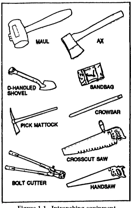
a. Handtools. The individual soldier is equipped with an intrenching tool and, if necessary, he can use his bayonet to assist in digging. Pick mattocks, shovels, and other tools are also useful, and frequently available for this purpose (fig 1-1). In addition, captured enemy equipment may be available. The relative value of each tool depends on the soil and terrain. In arctic areas, a larger quantity of picks and pick mattocks are required to aid in the preparation of emplacements in frozen ground.
b. Equipment. Relatively narrow cuts with steep or nearly vertical sides required for most emplacements or shelters can be excavated more accurately by hand. However, intrenching machines, backhoes, bulldozers, bucket loaders, and scrapers may be where the situation will permit the use of heavy equipment. Usually, these machines cannot dig out the exact shape desired or will dig more earth than necessary, requiring completion of the excavation by hand. Additional revetment material is usually required when machines are used. Distinctive scars on the ground resulting from the use of heavy equipment require more effort for effective camouflage than fortification work performed by hand.
c. Explosives. Many fortification tasks are
[image:10.612.327.549.130.483.2]made easier and accomplished more quickly by using explosive in any type of soil. Special explosive digging aids available include the M2A3 and M3 shaped demolition charges, and the field expedient det cord wick.
Figure 1-1. Intrenching equipment.
SECTION IV. Construction of Individual Emplacements 1-12. TYPES OF EMPLACEMENTS
a. Hasty emplacements. Hasty emplacements are dug by troops in contact with the enemy, when time and materials are limited. Hasty positions should be supplemented with overhead cover and strengthened as conditions permit. If the situation permits, the small unit leader will verify the sectors of observation and fire for the individual members
of the squad from their designated positions before they dig individual foxholes. When the situation is stabilized, even temporarily, positions are selected so they can be connected by trenches later. The emplacements described below provide
protection against flat trajectory fire. They are used when there is no natural cover. Hasty
positions (figure 1-2) are good for a short time because they give some protection from direct fire. If the unit remains in the area, they must be developed into well-prepared positions to provide as much protection as possible.
Figure 1-2. Hasty positions in an open field. (1) Shell crater. A shell or bomb crater of adequate size, 0.6 to 1 meter (2 to 3 ft), offers immediate cover and concealment and can be quickly made into a hasty position (figure 1-3). By digging the crater to a steep face on the side toward the enemy, the occupant can provide himself with a firing position. A small crater can later be developed into a foxhole. Craters, even if developed, are susceptible to being overrun by tracked vehicles.
Figure 1-3. Improved crater.
(2) Skirmisher's trench. This shallow pit type emplacement (fig 1-4) provides a temporary open prone firing position for the individual soldier. When immediate shelter from heavy enemy fire is required and existing defiladed firing positions are not available, each soldier lies prone or on his side, scrapes the soil with his intrenching tool, and piles it in a low parapet between himself and the enemy. In this manner, a shallow body-length pit can be formed quickly in all but the hardest ground. The trench should be oriented so that it is least vulnerable to enfilade fire. A soldier presents a low silhouette in this type of emplacement and is protected to a limited extent from small arms fire. It can be further developed into foxhole or a prone emplacement.
Figure 1-4. Skirmisher’s trench.
(3) Prone emplacement. This emplace-ment (fig 1-5) is a further refineemplace-ment of the skirmisher's trench. The berm dimension of this emplacement, as shown in the parapet detail, is varied to conform to the position and arm length of the occupant. It serves as a good firing position for a rifleman and provides better protection against small arms or direct fire weapons than the improved crater or skirmisher's trench.
Figure 1-5. Prone emplacement.
b. Foxholes. Foxholes are the individual rifeman's basic defensive position. They afford good protection against enemy small arms fire and can be developed from well chosen craters, skirmisher's trenches, or prone emplacements. Foxholes should be improved, as time and materials permit, by revetting the sides, adding expedient cover, providing drainage, and excavating a grenade sump to dispose of handgrenades tossed into the hole by the enemy.
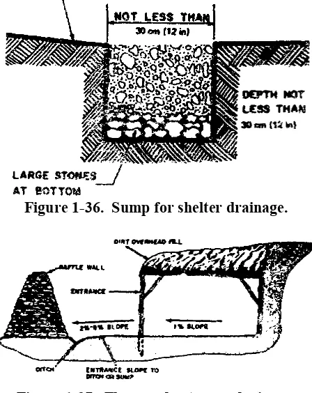
(1) One-man foxhole. The overall dimen-sions and layout of the one-man foxhole are shown in figure 1-6.
(2) Construction details.
(a) Fire step. The depth of the fire step will vary depending on the height of a comfortable firing position for the occupant, usually 1 meter to 1.5 meters (3 1/2 to 5 ft). The occupant, crouched in
Figure 1-6. One-man foxhole.
a sitting position on the fire step, must have at least 60 cm (2 ft) of overhead clearance if a tank overruns the foxhole. This will normally provide protection against the crushing action of tanks; however, in loose unstable soils it will be necessary to revet the walls of the foxhole in order to provide this protection.
(b) Water sump. A water sump, 45 cm (18 in.) by 60 cm (2 ft.) and 45 cm (18 inches) deep below the fire step, is dug at one end of the foxhole to collect water and to accommodate the feet of a seated occupant. One or two layers of large stones are then placed at the bottom of the hole with smaller stones on top up to the level of the ground (fig 1-6). The sump may simply provide a collecting basin from which water can be bailed.
(c) Grenade sump. A circular grenade sump large enough to accept the largest known enemy grenade and sloped downward at an angle of 30° is excavated under the fire step beginning at the lower part of the fire step riser. Handgrenades thrown into the foxhole are exploded in this sump, and their fragmentation is restricted to the unoccupied end of the foxhole. For good drainage and to assist in disposing of grenades, the fire step is sloped toward the water sump, and the
bottom of the water sump is funneled downward to the grenade sump.
(d) Parapet. If excavated spoil is used as a parapet (fig 1-6), it should be placed as a layer about 1 meter (3 feet) wide and 30 cm (6 inches) high all around the foxhole leaving an elbow rest (berm) of original earth about 60 cm (1 foot) wide next to the foxhole. If sod or topsoil is used to camouflage the parapet, the sod or topsoil should be removed from the foxhole and parapet area, set aside until the parapet is complete, and then placed on top in a natural manner.
(e) Camouflage. Whether or not a parapet is constructed in wooded or brushy type terrain, a foxhole can be camouflaged effectively with natural materials, as shown in figure 1-7. In open or cultivated areas, it may be preferable to omit the parapet, remove the excavated soil to an inconspicuous place, and improvise a camouflage cover for the foxhole. This can be a light, open frame of branches garnished with grass or other natural foliage to match the surroundings. As an alternate method, the foxhole can be covered with a shelterhalf, poncho, or other expedient material, and further covered with snow or some other material, according to local terrain conditions (fig 1-7). The occupant raises one side of the cover for observation or firing.
(f) Overhead cover. A half-cover (fig 1-8) over a one-man foxhole provides good protection for the occupant and permits full use of the weapon. Logs, 10 to 15 cm (4 to 6 in.) in diameter of 14 cm (6 in.) timbers approximately 1.2 meters (4 ft.) in length, support the earth cover. They should be long enough to extend at least 30 cm (1 ft.) on each side of the foxhole to provide a good bearing surface. Dirt should be removed on each side of the foxhole so that the supporting logs or timbers are even with the ground surface. If the ground is soft and tends to break away, a bearing surface of planks or timbers should be provided for cover supports. Logs or timbers of this size will support an earth cover 30 to 45 cm (1 ft to 1 1/2 ft) thick. The walls of the foxhole should be stabilized with revetment material (fig 1-9) at least under the
Figure 1-7. Camouflaged one-man hole.
overhead cover to prevent a cave-in from the added weight of the cover.
Figure 1-8. One-man foxhole with half cover.
Figure 1-9. Types of revetting material.
stakes (fig 1-10). Five or six strands of wire should be stretched between the revetment and anchor stakes at ground level and tightened by twisting. The distance between the revetment and anchor stakes should be approximately twice the depth of the excavation. The wire between the stakes should not pass over the parapet in any case.
Figure 1-10. Supporting and anchoring revetment.
(3) Open two-man foxhole. In a defensive position, the two-man foxhole (fig. 1-11) is generally preferred to the one-man emplacement.
Figure 1-11. Open two-man foxhole. (a) Advantages. One man can provide protection while the other is digging. It affords relief and rest, for the occupants as one man rests while the other observes. In this manner,
firing positions can be effectively manned for longer periods of time. If one
soldier becomes a casualty, the position is still occupied. The psychological effect of two men together permits positions to be occupied for longer intervals.
(b) Disadvantages. If a direct hit occurs, two men will become casualties instead of one. Also, the area that can be occupied may be reduced significantly.
(c) Construction. The two-man foxhole is constructed the same as the one-man foxhole except for the location of the grenade sump which is dug into the face of the foxhole towards the enemy.
(d) Overhead cover. A substantial overhead cover for a two-man foxhole may be provided by constructing an offset shown and described in figure 1-12. An alternate method is shown in figure 1-13.
c. Full frontal berm overhead rifle positions.
(1) Large positions are weak positions. Each rifle position should begin with a rectangular hole as long as the shoulder-to-shoulder length of the men who will fight in it, as wide as a man plus equipment. Spoil should be placed forward and to the sides to form a sloped, progressively packed berm.
Figure 1-13. Two-man foxhole with offset constructed of timber and culvert.
(2) The next step at the hole is to cut firing apertures at 45 degrees to the direction of the enemy and deepen the hole, tailoring the depth to each man, and carving elbow rests in the parapet for each rifleman to insure solid elbow-under-the piece firing positions. Apertures should be provided with grenade sumps and dug narrow and tapered,
just sufficient to command the assigned sector of fire (fig 1-14). Automatic rifles on
Figure 1-14. Rifle position.
bipods should have bipod rest slot cut forward to the parapet to allow the bipod to be withdrawn easily and to rest the gun muzzle low. The fitting for firing should be undertaken carefully to counter the natural tendency to shoot high at night. This is accomplished by digging each man down so that standing in his hole in firing position his piece is level at height for graze, firmly seated and supported, and as close to the ground as his mission permits.
(3) Overhead cover is now added. Cover can be fabricated from large logs plus sandbags or dirt, or sapling/bamboo mats in three crosslaid laminations plus sandbags or dirt, but should be sturdy enough to take the full weight jumping of a large combat-loaded soldier. Full overhead cover is constructed over all positions; full cover cuts vulnerability to airbursts and grenades, and lessens prospects of flooding in the event of rain. Care must be exercised to hold the silhouette of the position as low as possible, and the apertures as small as sector of fire permits. The height of the cover is determined by placing the firers in the hole, and the cover adjusted a full inch above their helmets while they take up night firing positions -head high over the sights. Berms and apertures should be extended and sloped forward to cut vertical surfacing, and to hide muzzle flash from the front. Construction of revetted, walls and overhead cover should follow principles outlined in b above.
(4) Camouflage is now added. Preferably this should be rooted plants and grass sod, calculated to grow naturally in place on the position, and to blend fully with the surrounding vegetation. While digging the fighting position, maximum care should be taken to prevent the destruction of natural camouflage growing near the hole, scaling off the sod to a depth that will maintain the roots, and setting it aside to be used for camouflage upon completion of the overhead cover.
(5) A rear entrance is now dug. This rear entry should be an auxiliary, fully open, individual firing position that can be used for
throwing grenades and M79 fires. It should
Figure 1-14. Rifle position (Continued)
be, at minimum designed to allow entry into the hole from the rear, covered with a poncho or similar screen to cut down backlighting the firing apertures. Full consideration should be given to protecting defenders from friendly direct fire weapons located to the rear of the position (including artillery beehive ammunition), and to emergency resupply. The sleeping position should be directly behind the fighting position. A completed rifle position (except for camouflage) is shown in (3), figure 1-14.
(6) A machinegun position is constructed generally following the same procedure as for the rifle position, except that the hole must be designed around the gun. The first step is to emplace the gun on its final protective line and walk the latter to check the site. The hole is then traced to place a sturdy firing table with working room for the loader on the left.
d. Overhead cover for foxhole (fabric).
When available Overhead Cover for Foxholes (OCF) is an effective protection for 1-and 2-man foxholes (fig 1-15).
(1) Description. The foxhole cover is a woven dacron fabric laminated to polyester film. It is 1.5 meters (5 feet 4 inches) long by 1.8 meters (6 feet) wide and weighs slightly less than 2 pounds. Connected to each side of the width are tubular sections, 15 centimeters (6 inches) in diameter and 1.5 meters (5 feet 4 inches) long. It will support 45 centimeters (18 inches) of soil over any emplacement, while simultaneously withstanding the blast effects of a nuclear weapon. The unit will cover 1- and 2-man foxholes and is capable of combining in multiple to cover shelter portions of crew-served weapons emplacements. It will function over emplacements 25 percent larger than standard.
(2) Installation.
Figure 1-15. Overhead cover for foxhole (fabric). (b) Allow a minimum of 60 centimeters
(2 feet) of open space at one end to permit entrance into the foxhole. Be sure that the cover extends at least 10 centimeters (4 inches) beyond the closed end of the foxhole ((1), fig. 1-16). This will insure that oil does not slide down the end wall of the foxhole.
(c) Mark the inside (nearest foxhole) edge of the pouches in the soil on both sides of the trench. Using the marked lines as the inside edge, dig two (one on each side) shallow trenches approximately 10 centimeters (4 inches) deep, 25 centimeters (10 inches) wide, and 1.67 meters (5 feet
6 inches) long parallel to the length of the foxhole ((1)
,
fig. 1-15).(d) Using entrenching tool, fill one pouch with soil using both ends as filling points. Fill other pouch in the same manner. Stretch the cover taut between the two pouches because a taut cover does not sag as much as a loose cover
((2), fig. 1-15).
(e) Place soil backfill around the edges of the foxhole to a depth of 45 centimeters (18 inches) minimum. The sloping outside soil edge should cover the soil filled pouch ((3)
,
fig. 1-15).(f) Complete covering with soil to a uniform depth of 45 centimeters (18 inches) but continue placing soil from the edges toward the center ((4), fig 1-15).
(g) Snap fasteners on each end of the cover provide means of covering a trench by connecting two or more covers ((5), fig 1-15), When connecting two or more units to form a covered trench type structure, it is essential that only steps 1 through 3 should be completed before connecting successive units. Any two units to be connected should be connected with the five middle snaps before the pouches of the second one are filled with soil. After the pouches are filled, the eight remaining snaps should be connected. Step 4 may be completed before all covers are erected over the trench but only on units positioned two or more units back from the last one connected.
1-13. FIELDS OF FIRE
a. Principles. There is little opportunity to clear fields of fire when a unit is in contact with the enemy. Individual riflemen and weapons crews must select the best natural positions available. Usually, there is only time to clear areas in the immediate vicinity of the position. However, in preparing defensive positions for expected contact with the enemy, suitable fields of fire are cleared in front of each position. The following principles are pertinent:
(1) Excessive or careless clearing will disclose firing positions (fig. 1-16).
(2) In areas organized for close defense, clearing should start near the position and work forward at least 100 meters (328 ft) or to the maximum effective range of the weapon if time permits.
(3) A thin natural screen of vegetation should be left to hide defensive positions.
b. Procedure.
(1) Remove the lower branches of large scattered trees in sparsely wooded areas.
(2) In heavy woods, fields of fire may
Figure 1-16. Clearing fields of fire.
neither be possible nor desirable within the time available. Restrict work to thinning the undergrowth and removing the lower branches of large trees. Clear narrow lanes of fire (fig. 1-17), for automatic weapons.
(3) Thin or remove dense brush since it is never a suitable obstacle and obstructs the field of fire.
(4) Cut weeds when they obstruct the view from firing positions.
(5) Remove brush, weeds, and limbs that have been cut to areas where they cannot be used to conceal enemy movements or disclose the position.
(7) Cut or burn grain, hay, and tall weeds.
(8) Whenever possible, check position from
the enemy side to be sure that the positions are effectively camouflaged and they are not revealed by clearing fields of fire.
Figure 1-17. Clearing fire lanes.
Section V. Construction of Crew Served Infantry Weapons Emplacements
1-14. PRINCIPAL CONSIDERATIONS a. Firing positions. While it is desirable to give maximum protection to personnel and equipment, the principal consideration must be the effective use of the weapon. In offensive combat, infantry weapons are sited wherever natural or existing positions are available or where weapons can be emplaced with a minimum of digging. The positions described in this section are designed for use in all types of terrain that will permit excavation.
b. Protection. Protection of crew-served weapons is provided by emplacements which give some protection to the weapon and crew while in firing positions. As the positions are developed, the emplacements are deepened and provided with half overhead cover, if possible. Then, if the positions are occupied for an extended period of time, shelters adjoining the emplacement or close to it should be built. Characteristics of crew served infantry
weapons emplacements are shown in table 1-2. (located in back of book).
c. Crew shelters. Shelters immediately adjoining and opening into emplacements improve the operational capability of the crew, since the men are not exposed when moving between the shelter and the weapon.
1-15. MACHINEGUN EMPLACEMENTS a. Pit type. The gun is emplaced initially in a hasty position (fig. 1-18).
b. Horseshoe type. The dimensions and layout of the completed emplacement are shown in figure 1-19. The horseshoe shaped trench, about 60 centimeters (2 feet) wide, is dug along the rear and sides, leaving a chest-high shelf in the center to serve as the gun platform. The spoil from this trench is used
Figure 1-18. Planview and cross section of machinegun emplacement.
Figure 1-19. Horseshoe type machinegun emplacement.
to form the parapet, making it at least 1 meter (40 inches) wide and low enough to permit all-round fire. This type emplacement permits easy traverse of the gun through an arc of 180°, but the crew cannot fire to the rear effectively. The firing table must be reverted to prevent the vibrations of the automatic weapons from breaking down the walls of the table.
c. Two one-man foxhole type. This emplacement consists of 2 one-man foxholes close to the gun position as illustrated in figure 1-20. The parapet is low enough for all-round fire and good protection for the crew, A foxhole is dug for the gunner at the rear of the gun and another foxhole is dug for the assistant gunner on the left of the gun and 45 cm (18 in.) in front of the
gunner's foxhole. The spoil is piled all around the position to form a parapet, care being taken to pile it so as to permit all-round fire of the weapon. Although 360° fire is possible from
this position, fire to the front or rear is most effective since the M60 machinegun is fed from the left side.
1-16. EMPLACEMENTS FOR RECOILLESS WEAPONS
a. Types. Two types of open emplacements for recoilless weapons are the pit type and the two two-man foxhole type.
(1) Pit type. This emplacement is a circular pit about 1.2 meters (4 feet) in diameter and about 1 meter (40 inches) deep depending on the height of the occupants. A parapet should not be constructed for this emplacement because of the backblast. It is large enough for two men and permits the assistant to turn with the traversing weapon, to avoid being behind it when it is fired. This emplacement is shallow enough to permit the rear end of the weapon to clear the top at maximum elevation, thus insuring that the hot backblast of the rockets is not deflected to the occupants. Since this emplacement offers protection for the crew against direct fire weapons only, supplementary personnel emplacements should be provided ((1), fig. 1-21).
(2) Two two-man foxhole type. The emplacement shown in (2) figure 1-21 provides
limited protection for the crew against nuclear effects and armor except when actually firing.
b. Blast effects. Due to the backblast effects of the recoilless weapon, it should not be fired from a confined space such as a fully covered emplacement. Because the backblast will reveal the firing position, alternate firing positions with the connecting trenches should be constructed if there is sufficient time.
1-17. MORTAR EMPLACEMENTS
a. General. The emplacement illustrated in (1), figure 1-22 is circular in shape. The emplacement is excavated to the dimensions shown with the sides of the emplacement sloping inward toward the bottom. The floor slopes to the drainage sump located under the open gap in the parapet. An ammunition ready rack or niche, located so that it is convenient for the gunner, is built into the side of the emplacement. The bottom of the ammunition rack is elevated from the floor of the emplacement. Another ready
rack may be constructed in one side of the
trench leading to the position. The initial emplacement is revetted using sandbags and
the improved emplacement is revetted using
Figure 1-22. Mortar emplacements.
corrugated metal. Before constructing the parapet, the mortar is laid for direction of fire by the use of an aiming circle or alternate means. The parapet should be not more than 50 cm (20 inches) high and a minimum of 1 meter (3 feet) wide. An exit trench may be constructed leading to personnel shelters and to other mortar positions. Construction of the parapet should be coordinated with the infantry commander.
b. The 81-mm mortar. A pit type emplacement for the 81-mm mortar is shown in (2)
,
figure 1-22.c. Emplacement for 4.2-inch mortar. The 4.2-inch mortar emplacement is identical to the one
described above for the 81-mm mortar except for dimension changes shown in (1), figure 1-22.
1-18. EMPLACEMENT FOR 106-mm RECOILLESS RIFLE OR TOW MISSILE (JEEP MOUNTED)
These weapons are often fired from their 1/4-ton truck mounts since the weapons should be mobile and moved to new positions after firing a few rounds. In a defensive operation, several open pits should be constructed with concealed routes from these firing positions to a concealed shelter position with overhead cover. The weapons remain in the shelter until needed, then after firing, they are moved to other firing positions or back to their shelters. The firing pit for these weapons should protect the sides and front of the body of the vehicles. The rifle or TOW should be above the parapet level. The rear of the emplacement should be ramped so the vehicle can move out quickly. Emplacements of this type require approximately 30 manhours to construct since alternate positions are required, so the necessity for using heavy equipment is obvious. Figure 1-23 illustrates an emplacement for the 106-mm recoilless rifle which will permit the weapon muzzle to extend over the parapet to preclude damage to the vehicle from the muzzle blast.
Figure 1-23. Emplacement for 106-mm rifle TOW missile.
Section VI. Construction of Vehicle and Artillery Emplacements
1-19. TYPICAL VEHICLE PIT
Digging in should be restricted to essential vehicles. Vehicle pits should be as narrow and as short as the vehicle size permits. They should be oriented randomly. All canvas should be removed and the top of the trucks should be at least 1 foot below the top of the surrounding parapet. The excavations should be as shown in table 1-3 and figure 1-24. Use of soil in construction of the
Figure 1-24. Typical vehicle pit.
parapet reduces the depth of cut necessary to properly protect a vehicle. The parapet should be streamlined and as well compacted as possible. The majority of vehicles should be concealed or camouflaged, with advantage taken of natural features such as woods, defilade, hegerows, and buildings.
1-20. TOWED ARTILLERY WEAPONS a. Purpose. Emplacements for artillery weapons must provide maximum flexibility in the
delivery of fire and protect the weapon and its crew against the effects of conventional and nuclear weapons.
b. Emplacement for 105- and 155-mm howitzer. Artillery weapons emplacements are constructed so as to allow for continuous improvement in order to provide additional protection and comfort in the event of prolonged occupation. These emplacements are developed in stages as described in (1) through (4) below.
(1) Stage 1. This stage provides open foxholes for the protection of the crew and open emplacements for infantry weapons used to defend the position. Provision is made for only minimum essential shifting of the gun trail and ammunition is stored in the open. Stage-one emplacement for a 105-mm howitzer is illustrated in figure 1-25.
(2) Stage 2. This stage provides trail logs for all around traverse of the weapon, a low parapet to protect the weapon, and covered emplacements for the crew, defensive weapons, and ammunition. Stage-two emplacement for a 105-mm howitzer is illustrated in (2), figure 1-25.
(3) Stage 3. In this stage a parapet revetted on the inside which permits
all around direction fire is provided. Work is
Figure 1-25. Development of 105-mm Howitzer emplacement.
begun on covered shelters for personnel and ammunition. Stage-three emplacement for a 10-mm howitzer Is illustrated in (3), figure 1-25.
(4) Stage 4. In this stage revetment is provided for the round fighting positions and for the outside and top of the parapet. Overhead cover is also provided for the personnel ready position and the ammunition shelter. Stage-four emplacement for a 106-mm howitzer is illustrated in) (4), figure 1-25 and (2), figure 1-26. Dimensions and layout are also shown in figure 1-26. Figure 1-27 shows semipermanent position for 155-mm howitzer.
(5) Use of overhead cover. It is usually difficult to provide overhead cover for artillery weapons. The widths and heights involved make such construction impractical under most conditions. Overhead cover would unduly restrict the firing capability of the weapon. In addition, under most conditions, it is not desirable to excavate an emplacement for the weapon much below ground level or to construct a high all-round parapet for the following reasons:
(a) A high all-round parapet restricts the direct fire capability of the weapon.
(b) An emplacement excavated below ground creates difficulty in rapid removal of the weapon from the emplacement.
c. Accessory structures.
(1) Ammunition shelters. Sectional shelters as described previously may be used with overhead cover as ammunition shelters with the types of weapons emplacements discussed above.
(2) Accessory shelters. Ready shelters for personnel and shelters for fire direction centers and switchboards are constructed using standard shelter designs.
1-21. SELF-PROPELLED ARTILLERY AND TANK-MOUNTED WEAPONS EMPLACEMENT
a. Self-propelled artillery. Large caliber
self-propelled weapons have a limited Figure 1-26. Final stage development, howitzeremplacement.
traverse without turning the vehicle. For this reason it is seldom practical to construct emplacements for this type of weapon. When positions for self-propelled weapons are prepared, a sloped ramp is built to facilitate the vehicle's entry into and withdrawal from the gunpit. In extremely cold weather, gravel, saplings, or similar covering may be necessary for the floor of the pit so that the tracks of the vehicles will not freeze to the ground. The rear of the pit and the sloped ramp should be widened sufficiently to permit driving the vehicle in at an angle in order to compensate for the limited traverse of the weapon.
b. Tanks. A tank is emplaced or protected in the same manner as any other vehicle. Natural defilades such as road cuts or ditches are used where available. In open areas, parapets are provided to protect the sides and front of the hull of the vehicle, and the rear is left open. The simplest form of a dug-in position of this type is shown in figure 1-28. Whenever possible, such positions are constructed and occupied during darkness, with all camouflage being completed before dawn. The emplacement
Figure 1-28. Dug-in emplacement for self-propelled weapons.
normally includes foxhole protection for relief personnel, preferably connected with the emplacement by a short trench. A dug-in emplacement of this type should have the following:
(1) An excavation deep enough to afford protection for the tracks and part of the hull of the vehicle with maximum thickness of the parapet at the front of the emplacement and the rear left open for entry and exit of vehicle.
(2) Inside dimensions just large enough to permit entry and exit of vehicle.
(3) An inside depth permitting the weapon to depress to its minimum elevation. Tank emplacements must have sufficient space for the storage of ammunition.
(4) Barrel stops, if necessary, to prevent fire into adjacent units.
(5) Provisions for drainage (if possible) and frostproof flooring to prevent tracks from freezing to the ground.
(6) If it is necessary to deliver fire at elevations higher than permitted by the carriage design, the floor must be sloped up in the direction of fire.
1-22. ARTILLERY EMPLACEMENT IN SOFT GROUND
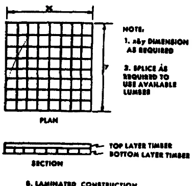
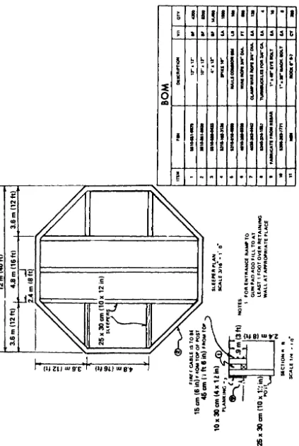
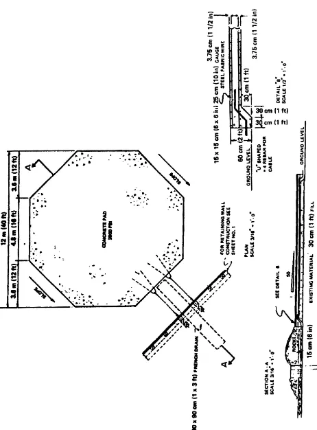
a. The siting of artillery positions in areas where the ground is soft requires the construction of pads to preclude differential settlement and thus the relaying of the weapon after each round is fired. Wooden pads can be built using laminated construction of radial sleepers (fig. 1-29) and other construction techniques. The wooden pad distributes the load over a large area with no significant settlement and is flexible and strong enough to withstand the turning and movement of self-propelled weapons. The trail logs are anchored just outside the pad for towed weapons. For self-propelled weapons, the recoil spades can be set in compacted material or in a layer of crushed rock just off the pad. Figure 1-30 shows position with pad for the 8-inch or 175-mm gun and figure 1-31 shows another pad for these guns which has non-radial sleepers and laminated flooring.
Figure 1-29. Radial and laminated gun pads.
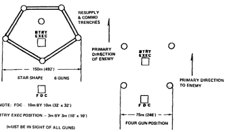
Figure 1-32 shows a concrete gun pad for these weapons. Figure 1-33 shows light and medium artillery battery layouts. Revetments and shelters can be constructed as described in paragraph 1-21.
b. Various synthetic materials, such as fiberglass mats (also used as helicopter landing pads), may be used as gun pads depending on the characteristics of the weapons.
[image:32.612.210.402.424.607.2]Figure 1-31. Gun pad for 8-inch or 175-mm with non-radial sleepers.
Figure 1-33. Light and medium artillery battery layouts. Section VII. Firebase Construction
1-23. DESCRIPTION
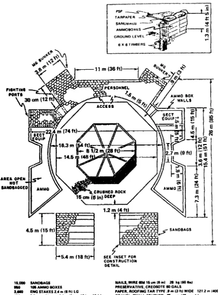
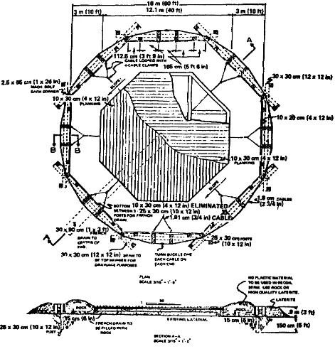
The airmobile division engineer battalion is equipped to construct artillery firebases in areas where ground transport is prohibitive. Especially in an unsophisticated environment, such as forest and jungle, these firebases play an integral part in airmobile operations, both as command posts and artillery firebases. The most frequently constructed firebase houses an infantry battalion command element, two infantry companies, a 105-mm howitzer battery and three to six 155-mm howitzers. A firebase housing the above units consists of the following facilities: infantry tactical operations center (TOC), artillery fire direction centers (FDC), ammunition storage pits, garbage sump, command and control helicopter pad, logistics storage area and slingout pad artillery firing positions, helicopter marking area and refuel point, and hardened
personnel sleeping positions. Firebases usually are surrounded by a protective berm with perimeter fighting bunkers, two or more bands of tactical wire and a cleared buffer zone to provide adequate fields of fire for perimeter defense. If a local water source is available, an airmobile engineer water supply point may be established to provide water for the firebase and units in the local area.
1-24. CONSTRUCTION
Construction of an airmobile firebase may be divided into three phases: combat assault and initial clearing, immediate tactical construction, and final defensive structures.
The time required to complete this phase depends on the terrain at the firebase site. If the site is free of trees and undergrowth, or if these obstacles have been removed by artillery and tactical air fire preparation, combat engineers can move immediately to Phase II after the initial combat assault on the site. If the site is covered with foliage and trees, the security force and combat engineers may be required to rappel into the site from hovering helicopters. Depending on the density of the foliage on the site, completion of the initial clearing phase by combat engineers with demolitions and chain saws may take up to three hours to accomplish.
b. Phase II. Phase II, immediate tactical construction, commences as soon as the cleared area can accommodate either medium or heavy lift helicopters. Two light airmobile dozers are lifted to the site and are immediately employed clearing brush and stumps to expand the perimeter and to clear and level howitzer positions. Meanwhile, the combat engineers continue to expand the perimeter with chain saws, demolitions, and bangalore torpedoes. If sufficient area is available, a heavy airmobile dozer usually is committed to clearing a logistic storage area and slingout pad, then to expanding the perimeter and fields of fire. The backhoes are committed to excavating positions for the infantry TOC, artillery FDC and, as soon as the perimeter trace is established, perimeter fighting bunkers. The immediate tactical construction phase is characterized by the coordinated effort of infantry, artillery, and engineer forces to produce a tenable tactical position by nightfall on the first day. It is a time of intense helicopter traffic introducing personnel, ammunition, barrier and bunker materials, rations, fuel, water, and artillery pieces onto the site. Aircraft traffic and logistics input must be rigidly controlled to preclude nonessential supplies and aircraft from hampering engineer effort. Therefore, a coordinated site plan and list of priorities for transportation and construction must be prepared and constantly updated. Priorities and the site plan are established by the tactical commander in coordination with the project engineer. As soon as a perimeter trace is established and the site is capable
of accepting the logistics and artillery lifts, maximum effort is directed toward the defenses of the firebase. Combat engineers and the heavy dozer continue to push back the undergrowth to permit adequate fields of fire. The two light airmobile dozers may be committed to construction of a 1.2 meter (4 ft) berm around the perimeter to protect against direct fire. Infantry troops are committed to constructing perimeter fighting bunkers at sites previously excavated by the backhoes and, assisted by combat engineers, begin erection of the first band of tactical wire, usually triple standard concertina. Artillery troops not committed immediately to fire missions prepare ammunition storage bunkers and parapet around each howitzer.
c. Phase III. Phase III, final defensive structures, is initiated as construction forces complete the immediate defensive structures. Combat engineers who are not placing the tactical wire or clearing fields of fire commence construction of the infantry TOC and artillery FDC. Infantry and artillery troops are committed to the second band of tactical wire and to erecting personnel sleeping positions with overhead cover. Culvert half sections lend themselves to rapid construction of these positions. Phase III is usually a continuous process, involving constant Improvement and maintenance; however, the majority of protective structures, including sandbag protection of the TOC and personnel bunkers, usually are completed by the end of the fourth day. The controlling parameter in construction of a firebase is time; since the firebase is the first phase of the occupation of a hostile area, the battalion command center and the artillery pieces must be operational as soon as possible and protection against direct and indirect fire requires immediate attention. Several techniques have been developed to increase the efficiency and speed with which construction can progress. Among these are precut TOC structures and the use of culvert as molds for protective bunkers. However, the most effective technique yet adopted is a closely coordinated and controlled plan, outlining the location, priority, and construction force for each phase of the mission.
1-25. FIREBASE LAYOUT
a. The primary purpose of the base is to provide positions for artillery. Thus, physical layout of the fire support base (FSB) will give best possible fields of fire to guns.
b. The base TOC will be located as near FDC as the base terrain allows. The TOC should be fairly centrally located and in a position to control base defense by visual means, if necessary.
c. The helicopter logistical pad should be within the base perimeter but be situated so that incoming and outgoing aircraft do not fly through the primary or most likely sector of fire of the artillery.
d. An admin/VIP helipad large enough for two UH-1 type aircraft should be located in the vicinity of the TOC.
e. If a helicopter rearming/refueling facility is located on the FSB, it should not be so near to either the gun positions or artillery ammunition storage pits that a fire or explosion of one will damage the others.
f. A landing zone for troop lift operations may be located outside the FSB but in the immediate vicinity of the perimeter positions.
g. Typical battery layouts are shown in figure 1-33.
1-26. ARTILLERY POSITION REQUIREMENTS
Engineer construction requirements for an artillery position within a firebase are generally as follows:
a. Platforms which allow the howitzers or guns to fire in all directions and be capable of supporting repeated firing shock in any type of soil condition.
b. Shelters capable of providing adequate protection for the firing crew.
c. Separate shelters large enough to contain an artillery section basic load of projectiles, fuzes, and propelling charges.
d. A wall or parapet around each howitzer or gun to protect the crew from fragments and small arms. The wall should be low enough to allow direct howitzer fire.
e. FDC/TOC shelters large enough to contain the personnel and equipment necessary for the operation of the fire direction center and tactical operations center.
Section VIII. Hasty Shelters 1-27. BASIC CONSIDERATIONS
a. Protection. Shelters are constructed primarily to protect soldiers, equipment, and supplies from enemy action and the weather. Shelters differ from emplacements because there are usually no provisions for firing weapons from them. However, they are usually constructed near or supplement the fighting positions. When natural shelters such as caves, mines, woods, or tunnels are available, they are used instead of constructing artificial shelters. Caves and tunnels must be carefully inspected by competent persons to determine their suitability and safety. The best shelter is usually the one that will provide the most
protection with the least amount of effort. Actually, combat troops that have prepared defensive positions have some shelter in their foxholes or weapon emplacements. Shelters are frequently prepared by troops in support of front unit. Troops making a temporary halt in inclement weather when moving into positions prepare shelters as do units in bivouacs, assembly areas, rest areas, and static positions.
b. Surface shelter. The best observation is from this type of shelter and it is easier to enter or leave than an underground shelter.
It also requires the least amount of labor to construct, but it is hard to conceal and
requires a large amount of cover and revetting material. It provides the least amount of protection from nuclear weapons of the types of shelters discussed in this manual. Surface shelters are seldom used for personnel in forward combat positions unless they can be concealed in woods, on reverse slopes, or among buildings. It may be necessary to use surface shelters when the water level is close to the surface of the ground or when the surface is so hard that digging an underground shelter is impractical.
c. Underground shelters. Shelters of this type generally provide good protection against radiation because the surrounding earth and overhead cover are effective shields against nuclear radiation.
d. Cut-and cover shelters. These shelters are dug into the ground and backfilled on top with as thick a layer as possible of rocks, logs, sod, and excavated soil. These and cave shelters provide excellent protection from weather and enemy action.
e. Siting. Whenever possible, shelters should be sited on reverse slopes, in woods, or in some form of natural defilade as ravines, valleys, and other hollows or depressions in the terrain. They should not be in the path of natural drainage lines. All shelters must be camouflaged or concealed.
1-28. CONSTRUCTION
a. Principles. Hasty shelters are constructed with a minimum expenditure of time and labor using available materials. They are ordinarily built above ground or dug in deep snow. Shelters that are completely above ground offer protection against the weather and supplement or replace shelter tents which do not provide room for movement. Hasty shelters are useful in the winter when the ground is frozen, in mountainous country where the ground is too hard for deep digging, in deep snow, and in swampy or marshy ground.
b. Sites for winter shelters. Shelter sites that are near wooded areas are the most desirable in winter because these areas are warmer than open
fields. They conceal the glow of fires and provide fuel for cooking and heating. In heavy snow tree branches extending to the ground offer some shelter to small units.
c. Materials.
(1) Construction. Work on winter shelters should start immediately after the halt so that the men will keep warm. The relaxation and warmth offered by the shelter is usually worth the effort expended in constructing them. Beds of foliage, moss, straw, boards, skis, parkas, or shelter halves may be used as protection against dampness and cold from the ground. Snow should be removed from clothing and equipment before entering the shelter. The entrance of the shelter is located on the side that is least exposed to the wind, is close to the ground and has an upward incline. Plastering the walls with earth and snow reduces the effect of wind. The shelter itself should be as low as possible. The fire is placed low in fire holes and cooking pits.
(2) Insulating. Snow is windproof, so to keep the occupant's body heat from melting the snow, it is necessary only to place a layer of some insulating material such as a shelter half, blanket, or other material between the body and the snow.
1-29. TYPES
a. Lean-to shelters. This shelter (fig. 1-34) is made of the same material as the wigwam (natural saplings woven together and brush). The saplings are placed against a rock wall, a steep hillside, a deadfall, or some other existing vertical surface, on the leeward side. The ends may be closed with shelter halves or evergreen branches.
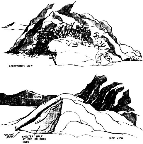
b. Two-man mountain shelter. This shelter (fig. 1-35) is useful, particularly in winter or in inclement weather when there is frequent rain or snow. It is basically a hole 2.1 meters (7 feet) long, 1 meter (40 inches) wide and 1 meter (40 inches) deep. This hole is covered with 6 to 8 inch diameter logs; then evergreen branches, a shelter half,
Figure 1-34. Lean-to shelter.