BEEHIVE
TERMINALS
REFERENCE MANUAL
for
BEEHIVE TERMINALS
MODELS I, II AND III
CD
m
m
:::E:
-<
m
S
m
C
-n
)::a
r-m
r-m
n
-t
::::c
c
:2
-
n
en
-:2
n
•en
C»-,....
r-C» =-::-CDn
_.
,....
'<
...
c:
,....
C»
=-TM-10A
REFERENCE MANUAL
for
TABLE OF CONTENTS
Section Page
INTRODUCTION ... 1
1.0
General ... 11.2 Functional Modes of Operation ... . ... 2
1.3
Keyboard Functions ...3
1.4
Communications Interface ...3
1.5
Beehive CRT Display Terminals (Basic Specifications) ... 81.6
Model I, II, III, Environmental Specification ...10
2
INSTALLATION AND OPERATION •.•..••.•....•...•...13
2.0
General ...13
2.1
Installation ...13
2.2 Operating Controls, Indicators, Switches ...
13
2.3
Terminal Turn-On Procedure ...21
2.4
Modes Of Operation - Basic Instructions ...22
2.5
Local Mode Operation ... , ... - ....24
2.6
Using the.Edit Function ... , ...25
2.7
Using the Format Capability ...,27
3
BEEHIVE TERMINAL DESCRIPTIONS ...30
3.1
Beehive Terminal Model I ...30
3.2
Beehive Terminal Model II ...32
3.3'
Beehive Terminal Model III ...34
3.4
Beehive Terminal Models I, II, III Option Description ...37
4
MAINTENANCE INSTRUCTIONS ....40
4.1
Parity Generation and Checking ....40
4.2
Baud Rate Adjustments in the Beehive Terminal ...40
4.3
Troubleshooting Hints ...46
5
PARALLEL INTERFACE CIRCUITS ....48
5.1
Technical Considerations ....48
5.2
Data To The Beehive Terminal ...48
5.3
Data From The Beehive Terminal ....48
Figure
1
2
3
4
5
6
7
8
9
10
11
12
13
14
15
16
Table
1
2
3
4
LIST OF I LLUSTRA TIONS
Page
Bit Serial Format ... 7
Functional Modes of Operation ... 11
Front View of Beehive Terminal ... 14
Beehive Terminal Monitor Controls ... 15
Side View of Beehive Terminal ... 16
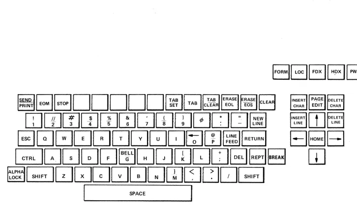
Model I Beehive Terminal Keyboard Layout ... - ... 31
Model" Beehive Terminal Keyboard Layout ... 33
Model" I Beehive Terminal Keyboard Layout ... 36
Card Cage Configuration ... .41
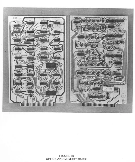
Option and Memory Cards ... .42
I nput and Output Cards ... .43
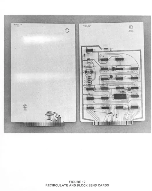
Recirculate and Block Send Cards ... .44
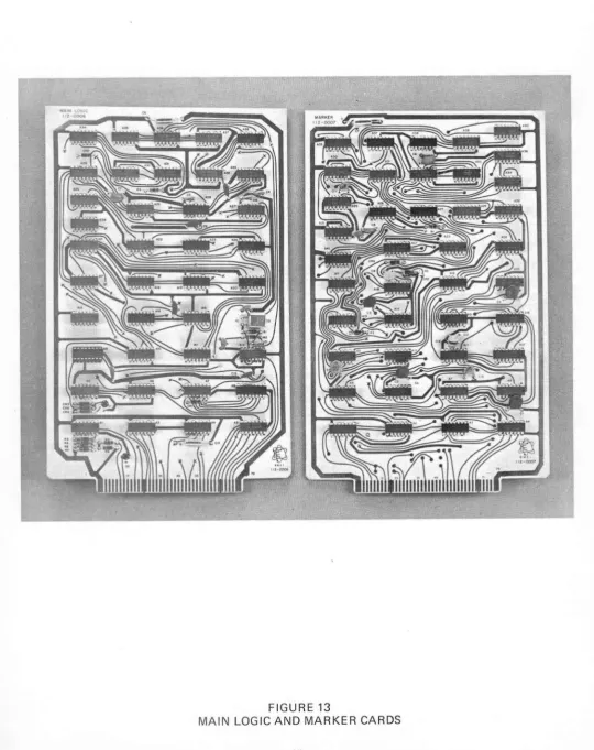
Main Logic and Marker Cards ... .45
I nterface Signal and Data Lines ... 50
Timing Diagram ... 51
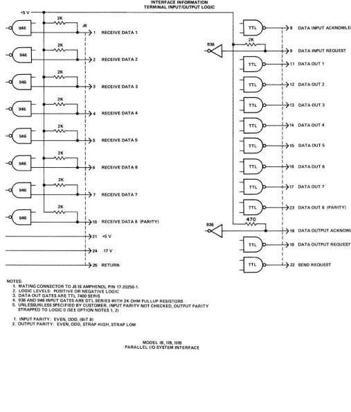
Interface Information Terminal I/O Logic ... 52
LIST OF TABLES Page ASCII Codes for Beehive Terminals ... .4
Operati ng Controls, I ndicators, Switches ... 17
Use of Terminal With Acoustic Couplers ... 23
[image:4.623.135.547.122.393.2]INTRODUCTION
1.0 GENERAL
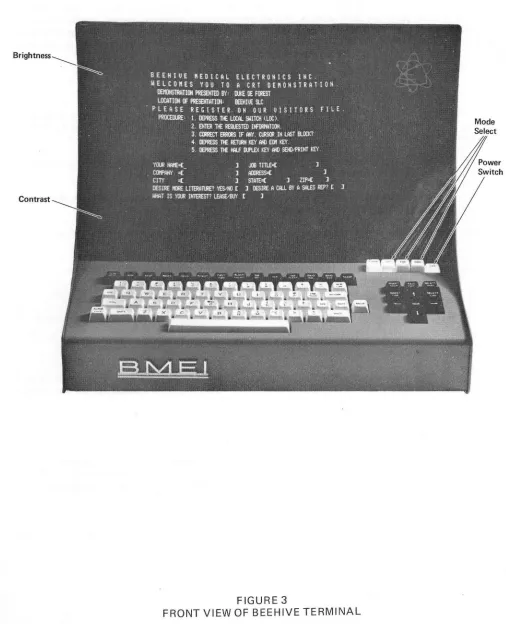
The Beehive Terminal is a complete operator-controlled computer display terminal which is used to transmit and receive information from an interfaced central computer. The Beehive Terminal consists of an alphanumeric keyboard, 12-inch CRT television monitor, character generator, interface logic, MaS memory and power supply. The equipment is designed to provide maximum operator desk-top convenience while occupying minimum space. Controls are provided at the front for power on/off, display brightness and contrast, and local/half-duplex/full-duplex operation.
The Beehive Terminal provides the following modes of operation:
1. Half-duplex: This is the normal conversational technique used to address the computer and accept replies following transmission. Transmission in the half-duplex mode is on a character-by-character basis with either the terminal or the computer controlling the communication channel during transmission. Data is displayed simultaneously as it is transmitted.
2. Full-duplex: The full-duplex capability permits two-way transmission between the terminal and the computer. The Beehive 'echoplex' technique is used wherein messages are transmitted from the terminal on a character-by-character basis and the computer 'echoes' (sends back) each character for display verification. This technique provides the operator with a character-by-character verification to ensure that the transmission from the terminal was correctly received by the computer.
3. Local Mode: In the local mode, messages can be written on the monitor screen, changed, edited, checked and observed for completeness and correctness without computer connection. With the Model I, this mode provides only local message generation for operator practice or other non-computer connected purposes, and the messages cannot be transmitted after display.
The Beehive Terminals provides a total display capacity of 800 characters with 40 characters on each of 20 lines with the capability of 1600 characters when Option A is included. The standard 64 character set
is used and agrees with the Standard Code for Information Interchange (ASCII); all data including
control information is received, stored, and transmitted using this ASCII convention. All characters may be checked for either even or odd (VRC) parity as they are received, with a parity error being
displayed as a question (?) mark in the character position. Parity is also selectable for all transmitted
data.
The display memory provides full storage for locally generated messages, cursor control'data, and for data received over the communications channel. Digital data and cursor information from the display memory are converted into video signals for the CRT display by the character generation logic.
The Beehive terminal keyboard is color coded to define two general areas of operation. The black keys are those which are used internal to the terminal only and will perform their normal control function in all modes. The white keys are those which are used in the normal modes of communication between the terminal and the computer and have in general the same physical arrangement as the Model 33/35 teleprinter.
One specific exception is the 'Here Is' key which is replaced by the 'New Line' key. Most other white keys have the same meaning as those on the conventional teleprinter.
If the terminal is in half duplex and a control code is generated by the white keys, the normal control function will occur. If a lower case code is received (in column 6 or 7 of the ASCII code sheet) it will be translated to the equivalent upper case code as defined by columns 4 and 5 unless the lower case option is installed (Option E).
A moving and blinking cursor on the display screen provides a continuous indication of the exact position in which the next character will be entered, received, or transmitted, and 4-way cursor controls allow the cursor to be shifted right, left, up, and down.
Transmissions between the standard Beehive Terminal and the computer is both directions is provided by a serial communication interface which allows operation with a voice-grade bandwidth data set (such as the WE type 103A/202 data set or other commercial equivalents) and acoustic couplers over any voice-grade communication network (such as switched dial up lines, or leased line telephone circuits).
Data from the standard Beehive Terminal is transmitted at 110, 150, or 300 baud, depending on the requirements of the particular application. Transmission may be synchronous or asynchronous, depending upon the type data set or mode used. The transmission code used is the standard 10 bit, 8 level ASCII code (start bit, 7 data bits, 1 parity bit, 1 stop bit). Reference Figure 1, Bit Serial Format. In addition to the three switch selected fixed baud rates, there are two variable baud rates available, i.e., 300 to 1200 baud and 1200 to 2400 baud.
The Beehive Terminal is equipped with a video driver which is capable of driving a remote television monitor or modified television set. A television distribution amplifier may be used to drive several monitors in different locations.
This terminal is designed to provide a keyboard data entry system that is fully compatible with existing time-sharing systems and with the additional features and flexibility required for the evolving batch processing and text editing applications.
1.2 FUNCTIONAL MODESOF OPERATION
Figure 2(A) shows the signal flow through the major circuits in the local mode of operation. Observe that there is no interface to the computer or any other external circuit. When a key is pressed at the keyboard the character code is transferred from the keyboard to keyboard logic through the output logic and then through the input logic circuit to the display logic and monitor screen.
Half-Duplex Operation
Full-Duplex Operation
Figure 2(C) shows the circuit configuration for full-duplex operation. When a key at the keyboard is pressed, the character code is transferred to the keyboard logic, output logic, and transmitted to the computer via the interface network. Each character code is 'echoed' (transmitted back) by the computer and is received at the terminal via the input logic. From the input logic the data flow is to the display logic and monitor screen. Note that no interconnection is made between the keyboard logic and the input logic; thus characters generated at the keyboard cannot be displayed except as they are echoed by the computer to verify that a correct message was transmitted and received. Messages generated at the computer are processed through the input logic and display logic as in the half-duplex mode.
1.3 KEYBOARD FUNCTIONS
All white keys on the keyboard, except the repeat key and break key generate the standard ASCII code shown in Table 1. Observe in Table 1 that some of the characters are unshifted (bottom position on key) and some are shifted (top position on key) and the shift key must be used to determine the precise character. Operation of the SH I FT key always changes bit 5 to its complement (ON ES to ZE ROS, ZE ROS to ONES). As an example of the shift function, observe that the only difference between the 4
and
$
is bit 5; a ONE for the 4, a ZE RO for the$.
In addition, Table 1 defines which codes are used for the individual keys and character and control keys. The CONTROL key always changes bit 7 to a zero. As an example of the control function, observe that a line feed command can be formed by operation of the LINE FEED key, CONTROL-J keys, and SHIFT-CONTROL-Z keys.
1.4 COMMUNICATIONS INTERFACE
General
This section describes the standard communications interface supplied with each Beehive Model I, II, or III terminal. It is characterized by:
1. EIA RS232B compatibility
2. Unpolled or contention operation
3. 10/11 bit start-stop asynchronous or synchronous serial transmission
4. Switch selectable baud rates of 110, 150,300 and variable from 300 to 2400 baud
5. Full or half duplex operation
Optionally, Beehive terminals can be obtained with:
1. Parallel I/O for data rates up to 660 characters per second
PS-llA 6/71
BITS
4321
0000
0001
0010
0011
0100
0101
0110
0111
1000
1001
1010
1011
1100
1101
1110
1111
~
Cassette Accessory7
6
5
TABLE 1
BEEHIVE TERMINAL USASC II CODES FOR MODELS I, II, AND III
PLUS OPTIONS AND CASSETTE ACCESSORY
00
0
NULL @
~
~~
~
-I
..
HOME SET HT BEL NL HT LF ERAS SCN ERAS LINE CR FORM OUT FORM IN Priority Blink Feature0
E
F
G
H
I
J
K
L
M
N
0
I
0
o
1
~
p
~
t
R
-
CLEART
U
CLRV
HT~
~.~~~~~~
:::;'~~':<~0::~
~,~~,
..~
~~
-,-
' -1~.vT~-·-"'-':::vmeg::==.1=:=
~'---~~----B:lii\l::K::&:-.:: .
1ID1~~
"IOE(f--'I~
Bts8'=::"=
~-"~,~.~'"'~~-1:B:t:tN:K=-"::I=.:I.~ I111111111111 Lower Case Optiono
1
0
SP
!
I I#
$
%
&
I(
)
*
+
I-.
/
o
1
1
1 0
0
0
@1
A
2
B
3
c
4
0
5
E
6
F
7
G
8
H
9
I
·
J
·
·
K
I
<
L
=
M
>
N
?
0
1 0
1
I .
~III'
1
P
II
I I
II
Q
I .
II
I' I
I '
R
I
1111~
i
I
I
I
IIIS
III
11111
I
T
II
III
,II
II
Ii
II
I
I
II
u
II
II
*11
1
I!
V
I
~III
I1I11
1111t
ll'
, I1I111
W
I
~II
" I I
'I~I
I111 i
I
IIIW'
I 1I1I1X
1I11I1I
I I' I
II~[II
I1I' '
i [1111
1III1
i
I
!'IT
Y
I
Ililll
,I ~Ii II
i II 111II1I' I I ! 1\
II
iZ
III
I·
II
11121,1
II
~
III
Ilhll
" IIII
III
III
HII
[
iI
II
III .. IIIII 1'1
I
III
r·\I
I\
i I
!
1'1Il111IJ
III
I11I11III
II
III~I
]
1'1 I.111
II
III
It
I
/\
I
II~!
III I I-
III11I
Interface Connection
The interface leads utilized when connecting a common-carrier data set that conforms to EIA RS232 are described as follows:
Connector Pin Number 1 2 3 4
5
6 7 20 Line Descriptions Line Description Frame Ground Transmitted DataReceive Data Request to Send Clear to Send Data Set Ready Signal Ground Data Terminal Ready
Circuit AA BA BB CA CB CC AB CD
Frame Ground (Circuit AA). This conductor, where used, is electrically bonded to the machine frame. Transmitted Data (BA). This circuit transfers data from the terminal to the data set for transmission to the remote processor. The terminal holds circuit BA in the Mark condition during any time interval between characters or words or when no signals are to be transmitted. Received Data (BB). This circuit transfers data from the data set to the terminal. Signals on this circuit are generated by the data set in response to data signals received from the remote terminal. The data set holds this line in the Mark condition when the line is idle or carrier is not detected.
Request to Send (CA). Signals on this circuit are generated by the terminal to condition the local data set to transmit. The On condition is maintained whenever the terminal has information ready for transmission or being transmitted. The terminal transmits data on circuit BA (Transmitted Data) only when the On condition is maintained on circuits CA, CB, and CC. In half-duplex service, the Off condition holds the data set in the Receive Data condition, and the On condition holds the data set in the Transmit Data condition.
Clear to Send (CB). Signals on this circuit are generated by the data set to indicate that it is prepared to transmit data. The On condition on circuit CA (Request to Send) is delayed as long as may be required to establish a connection to a remote terminal. When circuit CA is turned off, circuit CB is also turned off.
Data Set Ready (CC). Signals on this circuit are generated by local data sets to indicate that it is ready to operate. The Off condition indicates one of the following:
1. An abnormal or test condition occurs which disables or impairs the normal function associated with the class of services being furnished.
2. The communications channel is switched to alternate means of communications (e.g., alternate voice telephone); or
3. The local data set is not connected to a communications channel (e.g., the data set is on-hook).
The On condition appears at all other times.
ELECTRICAL CHARACTERISTICS
The terminal data set interfaces comply with the electrical requirements of the RS232 as described below:
All voltages are measured at the connector with respect to Signal Ground (circuit AB). The output line delivers between 5v and 25v into a resistance of at least 30.0.0. ohms. The input circuit will respond to voltage between 3v and 25v. The polarity of the signals depends on the following conditions:
Polarity
+
Data
Space Mark
Logic
0. 1
Control
On
Off
Voltage
+12 -17
The terminating impedence at the receiving end of the interchange circuit must have a value of not less than 30.0.0. ohms. The capacitance measured at the interface connector should not exceed 250.0. pf. The open-circuit voltage of the input circuits should not exceed 2v of either polarity.
For the data and timing circuits, the rise and fall time through the +3v to -3v range should not exceed 3 percent of the nominal bit time.
The following control lines, when used, are considered 'failsafe' lines:
Request to Send (CA)
Data Set Ready (CA)
Data Terminal Ready (CD)
.:...
•CD
=i
en
m
l1 : 0-:;g
' : 0 11m
0 ...
:0
s:
~
STOP PARITY
STOP
I
STOP 2 1BIT7 BIT6 BIT5 BIT4 BIT 3
10 BIT CODE
STANDARD AT 150 BAUD & HIGHER
PARITY BIT7 BIT6 BIT5 BIT4
11 BIT CODE
STANDARD AT 110 BAUD ONLY
BIT2 BIT 1 START
1.5 BEEHIVE CRT DISPLAY TERMINALS MODELS I, II and III (BASIC SPECIFICATIONS)
Display Format ... 20 Lines x 40 characters
Display Size ... Approximately 6" high x 9" wide
CRT Size ... 12" Rectangular
Character Size ... 0.1" wide x 0.2" high (approximate)
Character Type ... 5 x 7 dot matrix
Character Set ... 64 Character (USASCII)
Character Generation ... MOS Read Only Memory
Refresh Rate ... 60 Hz
Refresh Memory ... MOS Dynamic shift register
Page Overflow ... Upward Scroll. Top line is lost (on-line)
Page overwrite (local)
Parity ...•.... Parity (V RC) is checked on all received and
transmitted characters. Selectable Odd, Even or no parity. If no parity is desired, the parity bit may be strapped high or low. A parity error is indicated by a "?" in the character position containing the error.
Cursor Control ... 5 way ( left, right, up, down and home)
Cursor Type ... Non-destructive, blinking underscore
Communications Interface ... EIA RS-232. Fully compatible with Western Electric
Data Sets 103, 202, and 201 and equivalent
commercial modems. Will accept external clocking for synchronous operation.
Transmission Rate ... Se ri a I - up to 2400 BPS asynchronous or
synchronous, 7 level, 11 unit code (2 stop bits) at 110 BPS, 10 unit code (1 stop bit) at all high speeds. 11 unit code on all speeds available, if specified, at time of order.
Baud rate is switch selectable on the back connector panel of the terminal.
The baud rate switch has five positions marked: 110, 150, 300, variable 1 and variable 2
Transmission Code ... USASCII
Operator Controls ... Keyboard panel: Power, Full duplex, half duplex and local mode selector.
Monitor panel: Contrast, Brightness Back panel: Baud rate selector switch
Input Voltage ... 117 VAC plus or minus 10% 60Hz
Power Consumption ... 110 Watts maximum
Overload Protection ... Power supply and CRT individually fused. Power supply is current limited and over voltage protected.
Operation Temperature ... + 100 C to + 400 C Convection cooling
Humidity ... 20% - 80% non condensing
Terminal Size ... 14" high x 16" wide x 21" deep
Terminal Exterior Finish ... Armorhide Textured Vinyl
Colors: Light Blue U-216 (standard color) Off-white U-492 (optional color)
I/O Connectors ... BNC - Video Output
Standard 25 pin RS-232B connector Parallel I/O
Printer I/O
Keyboard ... Integral with the terminal. Layout is as indicated on the attached drawing for each specific Model.
Video Output ... Provides composite video signal capable of driving up to 500' of coaxial cable when terminated in 75 OHM. The signal is capable of driving most standard video monitors or customer provided distribution amplifier for mUltiple monitor installations.
1.6 MODEL I, II, III, ENVIRONMENTAL SPECIFICATION
Non-operating environment in
Temperature - 100C to 500C
Humidity - 5 - 80% non-condensing
Shock in shipping container - drop from 6 inches
Vibration - 43 Hz .045 in displacement
49 Hz .023 in displacement
51 Hz .020 in displacement
27.5 Hz
Altitude - 0 - 40,000 feet
.060 in displacement
Operating environment
4.1g's
2.89'S
2.69'S
2.3g's
Power - 100 - 125 VAC 60 plus or minus Y2 at 110 W maximum
Temperature - +50C for +450C and 5 minutes warm up maximum with power on
Humidity - 20 - 80% non-condensing
Vibration - normal office environment
INPUT LOGIC
.~
OUTPUT
.~
,
KEYBOARD
..
-
KEYBOARD DISPLAY..
MONITORLOGIC LOGIC
-
SCREEN(A) OPERATION IN LOCAL MODE
FROM ) '
--
INPUTCOMPUTER ' /
-
LOGIC.
,
KEYBOARD
-
KEYBOARD DISPLAY--
MONITORLOGIC LOGIC
-
SCREEN,
TO
«
OUTPUTCOMPUT.ER ~ LOGIC
(B) OPERATION IN HALF-DUPLEX MODE
FIGURE 2
FROM
>
COMPUTER
> - -...
-KEYBOARD ~--~=
TO
//1--_
...
COMPUTER "INPUT LOGIC
KEYBOARD LOGIC
I~
OUTPUT LOGIC
DISPLAY LOGIC
(D) OPERATION IN FULL-DUPLEX MODE
FIGURE 2
FUNCTIONAL MODES OF OPERATION (Sheet 2)
2.0 GENERAL
SECTION 2
INSTALLATION AND OPERATION
Operation of Beehive Terminal is completely operator-controlled. There are no special procedures or time-limited operational requirements with which the operator must be concerned. Messages may be typed at any speed up to approximately 30 characters per second, edited as desired, and transmitted in either half-duplex or full-duplex mode depending on the terminal-to-computer programming requirements. The local mode is used to compose, change, edit, practice, format, or for any other requirements where local data presentation is required without computer access.
2.1 INSTALLATION
The Beehive Terminal is fully self-contained and portable and can be installed in any convenient operating location to suit the opel'ator's requirements. The terminal can be moved from location to location as required.
Select a convenient and level desk top or table top and place the terminal in the operating location so that the power cable and data cables are out of the way.
Route the cables so that they will not be pulled, or kicked by other nearby personnel. Rotate the terminal on the holding surface so that it is conveniently oriented for the operator.
All connections are made at the rear-bottom of the terminal, as shown in Figure 4. Connect the cables as follows:
1. Connect the power cable to the right rear connector
2. Connect the interface (serial or parallel) to the appropriate I/O connector
3. Connector J 11 is for connection to the external printing device, if th is Option is included
2.2 OPERATING CONTROLS, INDICATORS, SWITCHES
The main operating controls are located at the front of the keyboard as shown in Figure 3. Table 2 describes the function of each operating control (other than keyboard functions) on the Beehive terminal; refer to this Table as required.
KEYBOARD FUNCTIONS
Includes control key cursor left, cursor right, cursor up, cursor down, and home. The cursor left and cursor right keys increment the cursor one position; and the cursor up and cursor down keys increment the cursor one line. The HOME key returns the cursor to the upper left-hand corner of the display.
REPT (White)
When pressed with another key, repeats any alphanumeric character, symbol or cursor function. Repeat speed is approximately 10 characters per second.
HOME (Black)
Brightness
[image:18.612.44.551.118.743.2]Contrast
FIGURE 3
Sync Connectors
Mon Power Switch
Focus
Horizontal
H
End of Line
Bell
[image:19.616.39.555.122.734.2]Brightness
FIGURE 4
TABLE 2
OPERATING CONTROLS, INDICATORS, SWITCHES
CONTROL/INDICATOR
POWER
CONTRAST
BRIGHTNESS
MODE
FORM
BAUD RATE SWITCH
LOCATION
Front upper right of Keyboard
Front Panel
Front Panel
Front upper right of Keyboard
Front upper right of Keyboard
Rear of Terminal
FUNCTION
Control power to logic and monitor.
Clockwise rotation increases contrast on display screen.
Clockwise rotation increases brightness on display screen.
Three-segment push button switch. Left position is
LOCAL mode; middle position is FULL- DUPLEX mode; right position is HALF-DUPLEX mode.
Alternate action lighted PB to select Format mode or indicate when Format mode has been selected .by the computer.
- (Black)
Moves cursor right one position. Continuous with REPEAT key pressed.
!
(Black)Moves cursor down one position. If cursor is on bottom line, cursor moves to top line. Continuous with REPEAT key pressed.
t
(Black)Moves cursor up one position. If cursor is on top line, cursor moves to bottom line. Continuous with REPEAT key pressed.
- (Black)
Moves cursor left one position. Continuous with REPEAT key pressed.
ALPHA LOCK (White)
This alternate action key, when not depressed, allows the keyboard to assume the identity of an upper case keyboard only, similar to the Teleprinter Keyboard. When the Alpha Lock Key is depressed, the keyboard assumes the role of an upper and lower case keyboard, i.e., all alphabetic keys will assume the same condition which one has· on a standard typewriter.
NEW LINE (White)
When this key is depressed, the cursor will be positioned at the beginning of the next line. The following codes are transmitted: Carriage Return, Line Feed, and Null, in that sequence. Note: This key is always an active key, even in local depressing it will cause a NEW LIN E function to take place.
CR (CARRIAGE RETURN) (White)
When this key is depressed, it shall cause the cursor to be returned to the left hand margin of the line that the cursor is on. Note: This key is active only in an on-line condition; in local it is stored and displayed as a lightly intensified 'M'.
LINE FEED (White)
When this key is depressed, it shall cause the cursor to go to the same character position on the next line down of the display Note: This key is active only in an on-line condition; in local mode, it is stored in memory and displayed as a lightly intensified 'J'.
CLEAR (Black)
When this key is depressed, the entire screen is cleared of all data and the cursor is returned to the home position. Note: This function is always active.
ESC (ESCAPE) (White)
CTRL (CONTROL) (White)
When this key is depressed, it forces the seventh row of the ASCII CODE to a condition which allows the various control functions to be performed. See Table 2. Note: In the local mode all control functions are
stored in memory and are displayed as lightly intensified characters. Example: Lightly intensified 'M' is
stored as a Carriage Return.
EOM (End of Message) (Black)
When this key is depressed, it causes the EOM symbol (\) to be displayed at the cursor position. If the display terminal is in a local mode, the cursor will then return to the home position. If the display terminal is in an on-line condition, the cursor remains at the position of the EOM and is transmitted at the time the key is depressed. Note: This is the only Black Key which is decoded to transmit as it is depressed.
SEND/PR INT (Black)
When this key is depressed, it causes the information to be sequentially transmitted from the cursor position to the EOM symbol. If the ter.minal is in a local mode, the sequentially transmitted data is routed out through the Print Connector J11. If the terminal is in an on-line mode, the sequentially transmitted data is routed out through the standard RS232-B communication interface J10. Note: When the cursor reaches the EOM symbol, a second symbol is then displayed indicating to the operator that the unit has sequentially transmitted the data and also transmitted the End of Message indicator.
INSERT CHARACTER (Black)
This is an alternate action key and when depressed, latches in the lower position which signifies the unit is in the Insert Chara.cter mode. Depressing any character key causes all characters from the cursor position to the end of the line to be moved right one position and the new character to be inserted at the cursor position. The last character on the line is discarded. The cursor moves right one position in the normal manner and additional characters may be added as necessary. Depressing the Insert Character key a second time unlatches it and removes the unit from the Insert Character mode. Refer to the Page Edit key for variation to the above.
DELETE CHARACTER (Black)
This key causes the character at the cursor position to be deleted and all data on that line to move left. A space is inserted into the last position of the line and the cursor remaining at its position. Refer to Page Edit key for variation to the above.
INSERT LINE (Black)
This key causes the line from the cursor position to the end of the line and all lower lines to be moved down one line. The 20th line is lost. The cursor remains at its initial position.
DELETE LINE (Black)
This key causes the line from where the cursor is located to be replaced by the next lower line. All lines below are moved up one line, with a blank line inserted into the bottom (20th line).
PAGE EDIT (Black)
treated as one continuous line of data. Insertion of a character in Page Edit mode shall cause all data from the cursor and to its right to be moved one position to the right. The last character on the page (display) is lost.
The Delete Character key, when in Page Edit mode, causes the reverse of the Insert function. The character at the cursor position is deleted and all data to the right of the cursor is moved left one position. A space is inserted into the last position ohhe display.
BREAK (White)
When this key is depressed, the data output line is put into a space condition for the equivalent of three character times through the 110.
TAB (Black)
When this key is depressed, it causes the cursor to advance to the next "Tab Set" position on the line. If there are no more "Tab Set" positions remaining on the line, the cursor will go to the first position on the next line. Note: In Format, the "Tab" key can be utilized to position the cursor to the next variable data field.
TAB SET (Black)
When this key is depressed, it causes a "Tab Set" point to be entered in the tab memory at the position of the cursor.
TAB CLEAR (Black)
When this key is depressed, it will clear any previously 'Tab Set" points from the TAB memory. Note: When the "Clear" key is depressed, all TAB SETS are cleared. If it is desirable to clear the screen and not clear the tabs, this can be done by the following sequence: Home, Erase Screen.
ERASE EOS (ERASE TO END OF SCREEN) (Black)
When this key is depressed, it causes all displayed information from the cursor to the end of the screen to be erased. Note: This does not erase any tab sets from the tab memory.
ERASE EOl (ERASE TO END OF LINE) (Black)
2.3 TERMINAL TURN-ON PROCEDURE
Before beginning to operate the Beehive Terminal, review carefully the function of each control and indicator and make sure that each keyboard function is clearly understood.
Perform the following procedures to turn-on the Beehive Terminal:
1. Place the POWER ON switch (right of the keyboard) in the ON position (DEPRESS).
2. Place MODE switch in LOCAL position.
3. Press the STOP and CLEAR keys and the cursor will appear in the upper left corner of the display screen within 2 minutes.
4. Type several characters in the four corners and in the center of the display screen.
5. Adjust the BRIGHTNESS control (UPPER) and CONTRAST (LOWER) control to display sharp, even characters.
2.4 MODES OF OPERATION - BASIC INSTRUCTIONS
LOCAL MODE
In the local mode no connection is made to the computer and messages may be composed, edited, checked and changed without affecting any external circuits. Unless the terminal is a Model II or III, messages composed with the terminal in the local mode cannot be transmitted to the computer. The cursor, in the local mode, may be moved about by the cursor control keys to allow the operator to add or delete characters, correct spelling or otherwise change or edit the message. When a message is being entered, the cursor automatically moves one character position to the right with each character entry to indicate the position for the next entry. As the cursor reaches the 32172 position of each line, the end-of-line "beep alert" sounds to alert the operator that the line ending is approaching. When the cursor reaches the right-hand end of a line it moves to the left-hand margin of the next line. If the last line (20th) has been written on, the cursor moves to the left hand margin of the top or first line (HOME position). New data as entered will overwrite on data which may not have been erased. To prevent overwriting, the EOL or EOS function may be used on the Model" and" I. Scrolling is not available in the LOCAL mode.
With a Model" and" I, in addition to the EOS/EOL feature, the TAB feature is also available. Use of the TAB feature is described as follows:
Setting Tabs
1. Press C LEA R key
2. Space cursor over to desired position for new tab
3. Press SET TAB key
4. Space cursor over to next desired position for new tab
5.
Press SET TAB key6. Continue this process to set tabs as required, then for practice, enter some columnar data to check that the tabs are entered properly.
Clearing Tabs
1. Press tab key to move cursor to tab which is to be cleared or changed
2. Press TAB CLEAR key to clear tab
3.
Press tab key to move cursor to next tab which is to be cleared or changed4. Press TAB CLEAR key to clear tab
5.
Repeat this process to clear individual tabs. Note that all tabs are cleared when the CLEAR button is pressed and the cursor is returned to the home (upper left) position.USING THE BLOCK SEND FUNCTION
1. Perform the turn-on procedures indicated on Page 21.
3. Place an end-of-message (EOM) symbol (') at the point you want transmission to stop.
4. Place cursor in position at which you want to begin the transmission.
5. Place mode switch in the half-duplex position.
6. Press SEND key.
7. You will observe the cursor moving along as the message is being transmitted, and the cursor will stop when it reaches the EOM symbol and a second EOM symbol will be displayed adjacent the original EOM symbol.
NOTE If you forget to place an EOM symbol in your message the terminal will continue to transmit until the STOP switch is pressed to reset the circuits.
HALF-DUPLEX AND FULL-DUPLEX OPERATION
In the on-line half and full-duplex mode, after writing the 20th line, the display will operate in a
scrolling fashion, i.e., the cursor returns to the left hand margin of the 20th line, and all previous written data will be caused to move up one line. The top line is discarded each time the display is scrolled up one line.
In both the half-duplex and full-duplex modes of operation, connection is made to the computer and most everything you do will have an effect on the computer. It is not possible to provide step-by-step learning procedures for these operations because each customer's computer situation is different. To practice in the half-duplex and full-duplex modes, call up your computer and exercise a problem which is
consistent with your particular applications, usin~ the Beehive Terminal with the mode switch in the
appropriate position.
Depending upon the type of coupler being utilized, the modes of operation selected on the terminal and on the coupler may be different. Special consideration must be given to the situation of full-duplex and half-duplex operation when an acoustical coupler is used to interface the terminal and the telephone line to the computer. The configuration of existing acoustical couplers is such that they simulate a full-duplex device, even if half-duplex operation has been selected. If the computer is operating in the full-duplex mode, both the coupler and the terminal must also be operating in the full-duplex mode. However, if the computer is operating in the half-duplex mode, the coupler and the terminal must be operating in different modes - one in full-duplex and one in half-duplex. Either combination can be used, but the preferred method, especially in a noisy transmission environment, is to place the coupler in the half-duplex mode and the terminal in the full-duplex mode. Table 3 defines the conditions for using Beehive Terminal with a coupler. If the modes of operation of the devices are not correct, the characters will be repeated on the display screen due to the echo back from the coupler along with the locally generated character.
TABLE 3
USING BEEHIVE TERMINAL WITH ACOUSTICAL COUPLERS
COMPUTER MODE
Full-Duplex Half-Duplex Half-Duplex COUPLER MODE Full-Duplex Half-Duplex* Full-Duplex
* Preferred method, especially with noisy transmission environment!;.
TERMINAL MODE
Full-Duplex
Full-Duplex *
2.5 LOCAL MODE OPERATION
The following procedures are intended to serve as traininq examples to acquaint the new operators with the techniques required to successfully operate the Beehive terminal in the local mode. Follow these examples step-by-step and you shouldn't have any problems quickly mastering the Beehive terminal.
Composing Messages in the Local Mode
1. Perform the terminal turn-on procedures
2. Type this message:
I AM COMPOSING THIS MESSAGE FOR THE
FIRST TIME ON THE BEEHIVE COMPUTER DISPLAY
TERMINAL. THE CRT TERMINAL IS NOW IN THE
LOCAL MODE AND I CAN DO ANYTHING I WANT
WITHOUT AFFECTING THE COMPUTER.
IF I HAVE TYPED THIS WITHOUT ANY ERRORS,
THE MONITOR SCREEN LOOKS JUST LIKE THIS
TEXT.
IF I HAVE MADE AN ERROR, I WILL NOW PUSH
THE CLEAR KEY AND BEGIN AGAIN UNTIL MY
DISPLAY IS CORRECT.
Correcting the Message in the Local Mode
1. Perform the terminal turn-on procedures
2. Type this message:
I AM NOW COMPOSING A MESSAGEWITH
AN ERROR OR THREE TO LERN HOW 2
CORRECT MY MISTAKES.
IF I HAVE TYPED THE ABOVE PARAGRAPH
WITH MY MISTAKES CORRECTLY AND MY
MONITOR SCREEN LOOKS LIKE JUST LIKE
THIS TEXT I WILL GO TO STEP 3.
MISTAKES I WILL PUSH THE CLEAR KEY
AND BEGIN AGAIN UNTIL I HAVE TYPED
MY MISTAKES AND EVERYTHING ELSE
CORRECTLY.
3. Move the cursor until the line is underneath the Win MESSAGEWITH.
4. Press LINE ERASE.
5. Press space bar once.
6. Type: WITH
7. Move the cursor until the line is under the T in THREE and press the ERASE SCRN key.
8. Type: TWO TO LEARN HOW TO CORRECT MY MISTAKES.
2.6 USING THE EDIT FUNCTION
The edit capability of the Model III terminal allows the operator extreme flexibility in message composition. Five keys (PAGE EDIT, INSERT CHARACTER, INSERT LINE, DELETE CHARACTER, DELETE LINE) provide the necessary control to insert a character, delete a character, insert a line, and delete a line.
The page edit switch enables the unit to do character insert and delete on either a line by line basis or a page basis. The page edit switch will remain depressed to indicate when the unit is operating in the page edit mode.
The insert character key is an alternate action key and when it is in a depressed position, this is an indication to the operator that the terminal is in an insert character mode. When a character key is then depressed, that character will be inserted at the position on the line where the cursor is located and all characters to the right of that position will be shifted to the right one position. The last character on each line is discarded if unit is not operating in page edit. If the unit is in page edit, the last character on each line is wrapped around to the beginning of the next line, and the last character on a full display is discarded. The cursor remains in the same position. New data can be inserted directly without affecting the rest of the display.
The insert line command causes spaces to be opened up from the position of the cursor to the end of that line. All subsequent lines are displayed one line position downward and the bottom line of data on a full display is discarded. The cursor remains in the same position. Successive commands provide additional cleared lines. New data can then be inserted directly without affecting the rest of the display.
The delete character command causes the character at the cursor position to be replaced by the character to its right. All characters to the right of the cursor are shifted left one space, and a blank space is inserted into the last position on the line if page edit is not employed, or on the screen if page edit is employed. The cursor remains in the same position. Successive commands provide additional closing of character positions.
Operate the Model III terminal as follows to use the edit function:
1. Perform the terminal turn-on procedures
2. Type this message:
I AM NOW COMPOSING A
MESSAGEWITH AN ERROR OR THREE
TO LERN 2 CORRECT MY MISTAKES.
IF I HAVE MADE MISTAKES IN MY
MISTAKES, I WILL PUSH THE CLEAR
KEY AND BEGIN AGAIN UNTIL I HAVE
TYPED MY MISTAKES AND EVERYTHING
ELSE CORRECTLY.
3. Check that the Page Edit key is not latched down. Move the cursor until the line is underneath the W in MESSAGEWITH.
4. Press the INSERT CHARACTER key.
5. Depress SPACE key one time to insert space between message and WITH.
6. Move the Cursor until it is underneath the T in THREE.
7. Depress the EOL key.
8. Depress the INSERT CHARACTER key a second time to take the terminal out of this mode.
9. Type: TWO, TO LEARN TO
10. Move the Cursor to the beginning of the next line, i.e., under the T of TO.
11. Depress the Delete Character key 11 times (correct should now be at the beginning of line three).
12. Position the Cursor under the R of M ISTRAKES.
13. Depress the Delete Character key a single time.
14. The message should now appear as follows:
I AM NOW COMPOSING A
MESSAGE WITH AN ERROR OR TWO
2.7 USING THE FORMAT CAPABILITY
The format capability is an important aid to the operator who must repeatedly fill in blank spaces of predefined forms which are stored in the computer. Typicallv the operator requests the form from the computer and it is transmitted to the Model III Terminal. The operator then completes the required information, and transmits this information to the computer.
The Model III Terminal is placed in the format mode upon receipt of a control 0 either from the keyboard from the computer, or by depressing the format switch. The format switch will illuminate when in the format mode. While the terminal is in the format mode, the monitor display is "file-protected" so that only the data between the opening bracket ([) and the closing bracket (] ) of any two bracket sets can be altered by the operator. The form data from the computer file cannot be altered.
In the format mode, only the variable data is transmitted.
The cursor skips the form positions and moves to the next opening bracket whenever a control I is received from either the computer or keyboard or by pressing the TAB key on the keyboard. The cursor also skips automatically to the next opening bracket whenever it is positioned under a closing bracket during a fill-in-the-blanks process.
The Model III terminal is removed from the format mode by receipt of a control N or deoressing the format switch aaain When the terminal is out of the format mode, the memory is not file-orotected, and the opening bracket, closing bracket, assume their usual meaning.
The code assignments for the format option are shown in Table 4.
NOTE: The opening and/or closing brackets must be displayed on the screen before placing the unit in the format mode. If this is not done, the Cursor will be lost and display of characters will be locked out. When this condition occurs, it will be necessary to depress Stop and Clear keys.
TABLE 4
FORMAT CODE ASSIGNMENTS
Automatic Skip control I
Format In control 0
Format Out control N
Opening Bracket shift K
Closing Bracket shift M
Format Erase control W
It is not possible to provide step-by-step learning procedures for the format mode because each customer's computer situation is different. The following example is offered in lieu of step-by-step procedures for using the format mode.
Form ABC
NAME [
ADDRESS - STREET [
-CITY
- STATE
AGE[ HEIGHT[
POSITION DESIRED [
EDUCATION - COLLEGE [
- HIGH SCHOOL [
ZIP
WEIGHT [ SEX [
The computer then sends the format-in code control 0 to position the cursor on the Model III to the first blank position in the form. The terminal has now been placed in the format mode and file protection is provided.
The operator then fills in all the blanks utilizing the keyboard to write the proper words and utilizing an HT to provide an automatic skip where required until the form has been completely filled out as shown below:
NAME [ John R. Doe
ADDRESS - STREET [ 231 East 4th South
-CITY Salt Lake City
-STATE Utah ZIP [ 84111 ]
AGE [ 36 ] HEIGHT [ 6' 2" WEIGHT [ 150] SEX [ M ]
POSITION DESIRED [ Engineer
EDUCATION - COLLEGE [ Utah State University
Normally the terminal is in either the half-duplex or full-duplex mode and the variable data is transmitted as it is composed. After the last character has been transmitted, the variable data in the form may be erased by performing a Form Erase, and the form can be used again.
All of the "fill in the blank" editing can be accomplished in the "local" mode of operation. When the operator is satisfied that all of the blanks are filled in correctly, the operator switches the terminal to the half-duplex mode and depresses the Send key, thereby transmitting only the variable data to the computer.
SECTION 3
BEEHIVE TERMINAL DESCRIPTIONS
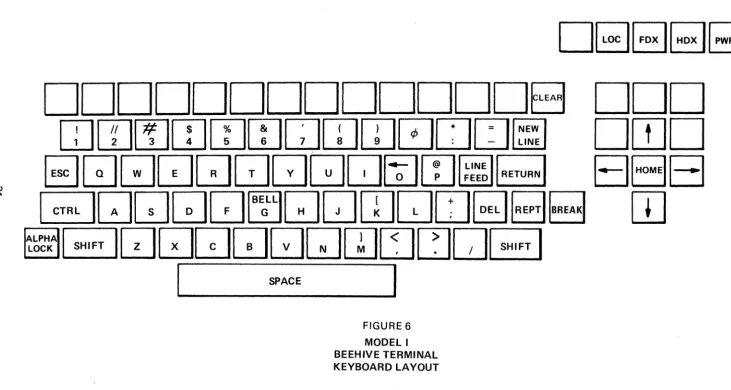
3.1 BEEHIVE TERMINAL MODEL I
The Model I provides the minimum functional capabilities required in an alphanumeric CRT display terminal. The unit is plug-to-plug compatible with the Teletype Models 33 and 35 teleprinters when the RS-232B type interface is used. 20/60 ma current loops may be handled by use of a TTY Loop Adapter (see Accessories).
The standard features of the Model I are:
Options:
Standard 53 key teleprinter style keyboard including an alpha lock function which allows the keyboard to operate as upper/lower case keyboard. All forbidden codes are disabled.
800 character storage and display (20 lines of 40 characters each)
Parity generation and detection - Strap Selectable
Remote composite video output available through BNC connector on rear panel connector plate
Upward scroll in "on-line"operation
Page overwrite in "local" operation
Four-way control of non-destructive blinking cursor
Cursor home and clear screen keys
Selectable baud rates of 110, 150, and 300 plus Variable 1 (300 - 1200) and Variable 2 (1200 - 2400)
Operator adjustment of contrast and brightness
Local, half and full duplex modes of operation
EIA RS-232B communication interface
64 character USASCII Code - lower case displayed as upper case
Dual intensity video - control characters lightly intensified and displayed in local mode
DE1[;][;][;J
DDDDDDDDDDDDDB DDD
mrn~wrnwQrnw0Du~
DrnD
w
EJGJ[;]QQuGGJQ~[IJillillr;;;]
B8El
~ ~QQQQ~QQrnQD~B~
w
~~~A ~DQDGJGJ[J[I]tJCJ[JB
[image:35.798.31.763.107.497.2]I
SPACEI
FIGURE 6
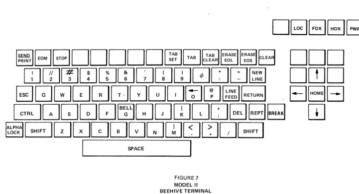
3.2 BEEHIVE TERMINAL MODEL"
The Model II provides the features of a Model I plus the additional features to enable use of the terminal in Batch oriented type applications. Note that it is possible to up-grade from a Model I to a Model II in the field.
The adaitional features of the Model II are:
Options:
Tab:
Erase:
Send/Print:
TAB SET, TAB CLEAR, and TAB. Permits inserting a tab "flag" at any character position on a line as indicated by the cursor position. The tab position remains available for character display.
Provides two Erase keys:
a. Erase to end of line (EOL). Erases all characters from cursor position to end of line.
b. Erase to end of screen (EOS). Erases all characters from the cursor position to the end of the screen.
Provides the ability to transmit a complete message or page of data for Batch applications. When in the Local mode, depressing the End of Message key (EOM) causes the EOM symbol to be displayed at the cursor position and the cursor to return to the Home position.
Depressing the SEND key with the mode switch to HDX position will cause the data contained within the cursor home position and EOM symbol to be transmitted via the send connector. The EOM character is also transmitted
NOTE
In the event Option C is installed, the Send/Print Key takes on the dual purpose, i.e., that described above when in the half duplex mode. In the local mode, when the send/print key is depressed, the information from the cursor to the EOM is transmitted through the Print connector to a customer furnished Serial ASC II pri nter device.
SEND
DDDDDDD~r-::l~~~c-:J
PRlNTUU
~L:J~~~u
I!llilll#ll$ll%lr&l
r-:I.
ITlIiI
!;lOU=
~
L.!..J
L1..JL2.J
~
~~
L2-Jl!..J
l2..J
L.:J:
-
~
[image:37.798.47.769.105.496.2]3.3 BEEHIVE TERMINAL MODEL III
The Model III provides all the features and functional capabilities of the Model I and II plus the following
features to enable the use of the terminal in a more sophisticated time sharing environment, or applications where editing and protected field formatting is a necessity. Note that it is possible to up-grade from a Model I or II to a Model III in the field.
The additional features of the Model III are:
Format: Provides the ability for either the keyboard or Program control to display a
fixed format with the appropriate blanks, which are to be filled in by the operator.
Variable data will be entered only between open ( [ ) and closing (] ) brackets. With the format enabled, only the variable data will be transmitted. The specifics for implementing this function are defined as follows:
a. The Model III may be placed into the format mode by use of a control
o
received from the keyboard or computer (if in an on-line mode ofoperation) or by depressing the alternate action lighted control switch which is labelled Form. The switch is illuminated when in the format mode.
b. While the terminal is in format mode, the CRT display is file protected.
That is, only the data between the opening bracket ( [ ) and the closing bracket (] ) of any two bracket sets can be altered by the operator.
C. The cursor (which defines the location of the next character to be
written) will skip to the next opening bracket by the following:
1. Receipt of a control I from the computer.
2. Being positioned under a closing bracket by the process of filling in the blanks.
3. Depressing the TAB key on the keyboard.
d. The Model III is removed from the format mode by receipt of the
control N code from the keyboard or the computer when in an on-line mode of operation, or by depressing the Form switch at which time the Form light is extinguished. When the terminal is out of the format mode, the memory is not file protected. In addition, the opening bracket, the closing bracket, and the HT codes take on their ordinary meaning.
e. The code assignments for the format option are:
OCTAL
Automatic skip 011
Format in 017
Format out 016
Opening bracket 133
Closing bracket 136
Options:
The format Erase capability provides a keyboard or computer initiated command (Control W) to erase all variable data and to home the cursor to the first variable character position.
Edit: This feature is active only in the local mode and provides the operator with the ability to manipulate the displayed data with minimum efforts. The Edit capability is inhibited when the unit is in the Format mode. There are five keys associated with this feature: Insert Character, Delete Character, Insert Line, Delete Line and Page Edit. The function of each key is as follows:
A,B,C,D,E
a. Page Edit. This is an alternate action key. When depressed latches in the lower position which signifies the unit is in the Page Edit mode. This key is used in conjunction with the Insert and Delete Character keys.
Its function is to eliminate the 40/80 character line boundaries so that all data on a screen (display) is treated as one continuous line of data. I nsertion of a character in Page Edit mode shall cause all data from the cursor and to its right to be moved one position to the right. The last character on the page (display) is lost.
The Delete Character key, when in Page Edit mode, causes the reverse of the Insert function. The character at the cursor position is deleted and all data to the right of the cursor is moved left one position. A space is inserted into the last position of the display.
b. Insert Character. Alternate action key when depressed latches in the lower position which signifies the unit is in the Insert Character mode. Depressing any character key causes all characters from the cursor position to the end of the line to be moved right one position and the new character to be inserted at the cursor position. The last character on the line is discarded. The cursor moves right one position in the normal manner and additional characters may be added as necessary. Depressing the Insert Character key a second time unlatches it and removes the unit from the I nsert Character mode.
c. Delete Character. This key causes the character at the cursor position to be deleted and all data on that line to move left. A space is inserted into the last position of the line and the cursor remaining at its position.
d. Insert Line. This key causes the line from the cursor position to the end of the line and all lower lines to be moved down one line. The 20th line is lost. The cursor remains at its position.
.
w en
.
FIGURE 8 MODEL III BEEHIVE TERMINAL KEYBOARD LAYOUT
IFORMIEJ81
HDXII PWR I
INSERT
I
p"GEI
DELETECHAR EDIT CHAR INSERT
rn
DELETELINE
I
LINEElBEJ
[image:40.804.31.758.64.507.2]3.4 BEEHIVE TERMINAL MODELS I. II. III OPTION DESCRIPTION
OPTION A: 80 Character Per Line option, which when incorporated in any Model I. II, or III CRT
Terminal, doubles the memory capacity of the Terminal (the number of characters per line doubles from 40 characters per line to 80 characters per line). The size of the character remains the same, the difference in the line capacity is brought about by the reduction of the spacing between characters.
This is a field installable option and can be installed by BMEl's national service organization.
OPTION B: Low Speed Parallel Interface option, which when incorporated in any Modell, II, or III CRT
Terminal, permits the terminal to interface to a computer in a hard wire connection with data rate of up to 660 characters per second. This option utilizes the standard Request/Acknowledge technique for synchronizing data transfers. The data is presented in a bit parallel character serial format. Standard logic levels are Logic 1
=
Ov and Logic 0=
+5 volts. The basic output gates are TTL Series Type 7400. The input gates are DTL Series Type 946, with a 2000 OHM pull up resistor. Unless specified by the customer at the time of order, the input parity is strapped to a Logic "0".Input parity may be specified at the time of order to check for either even or odd, output parity may be selected even or odd. Also, the logic levels may be inverted to provide a Logic 1 = +5 volts and Logic 0 = 0 volts. The parallel interface option is not a field installable option and must be selected at the time of order.
OPTION C: Serial RS-232B Remote Printer I/O option, which when incorporated in the Model II or III
CRT Terminal, permits the terminal to be interfaced to any off-line Serial ASCII RS-232B printing device. The point of connection shall be through J7 at the rear connector panel. When the terminal is in the LOCAL mode and the SEND/PRINT Key is depressed, all of the displayed information from the cursor position to the EOM symbol shall be transmitted via the Print Connector J7 to the remote (customer furnished) printing device.
A separate printer oscillator provides transmission rates up to
a
maximum of 4800 buad.The desired rate must be specified at time of order. An adjustment of plus or minus 20% of specified rate is available for customer fine tune.
This is a field installable option which may be installed by BMEl's national service organization.
OPTION D: Export Model option, which when incorporated in any of the Model I, II or III CRT
Terminals, enables the terminal to be operated from a 50 Hz, 200 to 260 volt power source.
This is not a field installable option and must be specified at the time of order.
OPTION E: Lower Case Display option, which when incorporated in any of the Model I-A, II-A or III-A
CRT Terminals, permits the terminal to display lower case alphabetic characters. Of the
lower case alphabetic characters, the following five characters, i.e., (g, j, p, q, y), with
decenders are positioned properly with the respect to the remainder of the lower case font. With this option installed, a total of 128 characters have the capability of being displayed.
NOTE
All control characters are displayed as lightly intensified characters.
This is a field installable option and may be installed by BMEl's national service organ ization.
OPTION F: High Speed Parallel Interface option, which when incorporated in a Model I, II or III CRT Terminal, permits the terminal to interface to a computer in a hardwired connection with a data rate of up to 10,000 char:acters per second. This option utilizes the standard Request/Acknowledge technique for synchronizing data transfer. The data is presented in a bit parallel character serial format.
This option shall be available in the second quarter of 1971.
OPTION G: Three Level Priority Blink option, which when incorporated in any Model I, II or III CRT
Terminal, permits the display of a character, word or message to be either blinked (Levell), reversed video (Level 2), or blinking reversed video (Level 3). It is possible to have all levels of the priority blink option active on an individual message. Activation of this option is available either from the keyboard or by the means of program control.
This is a field installable option and may be installed by BMEl's national service organization.
This option shall be available in the second quarter of 1971.
ACCESSORIES: TTY Current Loop Adapter, - This accessory, when added to any Model CRT Display
Terminal, allows interfacing of the terminal via its EIA RS-232B interface to a standard three or four wire teleprinter 20 or 60 milliamp current loop. This adapter is a stand-alone mini-box which houses the necessary interface relays, E IA RS-232B level converters, the appropriate loop battery supply, and the compatible connectors to make a complete stand-alone package.
Stand-Alone Cassette - The stand-alone cassette terminal is a cassette loaded magnetic
. tape terminal incorporating both a terminal compatible and a line compatible interface. the stand-alone cassette terminal provides the capability to function as a stand-alone batch processing station for point-to-point data transmission and as a companion unit to a Beehive Model I, II or III CRT Terminal device without hardware or system modification.
The stand-alone cassette terminal interface is compatible to standard data processing and communication equipment and includes selectable transmission speed to accommodate both high and low speed devices. The standard features of this terminal are as follows:
1. Plug to Plug compatible dual interfaces, communication line and operator terminal, both EIA RS-232B compatible.
2. The instant updating of the existing data.
3. Re-usable cassette magnetic tape storage.
4. Both read and write capability.
5. Unique storage technique provides 70,000 character storage on a single pass.
6. Capability of being able to record at one speed and play back at any other speed. Switch selectable speeds.
7. High Speed Search - Search rate is at approximately 1,000 characters per second. A maximum of 99 records may be identified by the search mode.
8. Human engineered with control and indicators for upmost in simplicity and clarity.
CABLES:
10. The terminal is system tailored with operator interlock to insure high reliability.
11. It is portable and can be located to suit your application.
12. 1200 baud high speed transmission rate.
The ability to converse freely, both directions to the communication line, has been maintained without degregation so that the applications can be accommodated where the operator input and machine stored input are intermixed.
The stand-alone terminal is completely compatible with present time sharing and computer system by utilizing the USA standard code for information interchange (USASCII). Since the line I/O interface conforms to EIA RS-232B standards it is compatible with all Bell Data Sets or equivalent modems and most acoustical couplers. Data services that can be attached to the terminal I/O interface include keyboard printers, CRT terminals, tape readers and punch combinations. For additional information on this terminal, consult the factory.
SECTION 4
MAINTENANCE INSTRUCTIONS
4.1 PARITY GENERATION AND CHECKING
The Beehive terminal, as shipped from the factory, is connected for no parity checking or generation.
The following instructions are for connecting parity check/generation capability into the terminal on the following boards (Reference Figure 9 ):
Input: Remove jumper between Com and None
Odd parity - Add wire from common to odd parity
Even parity - Add wire from common to even parity
Since a parity bit is always transmitted, even if none is required, there are four possible conditions for this bit. The parity bit can be forced always to a Mark (1 bit) or a Space (0 bit) Odd parity, or Even parity. The terminal is shipped with the Parity Generation Circuits wired for a Space condition.
Output: Remove jumper between Com and Space
Odd parity - Add wire from common to odd parity
Even parity - Add wire from common to even parity
4.2 BAUD RATE ADJUSTMENTS IN THE BEEHIVE TERMINAL
Fixed Baud Rate (110, 150,300)
To adjust the fixed baud rates (refer to Input Board Figure 11)
1. Jumper" R" and "G" together
2. Use digital frequency meter and connect leads to Clock and ground (G)
3. Adjust R3 for 110, 150 and 300 respectively
4. Remove jumper and meter leads
Variable Baud Rate (Variable 1 - 300-1200, Variable 2 - 1200-2400)
To adjust variable baud rate, refer to Output Board, (Figure 11)
1. J