Design, Implementation and Deployment of State
Machines Using a Generative Approach
Graham N.C. Kirby, Alan Dearle and Stuart J. Norcross
School of Computer Science, University of St Andrews, North Haugh, St Andrews, Fife KY16 9SX, Scotland {graham, al, stuart}@cs.st-andrews.ac.uk
Abstract. We describe an approach to designing and implementing a distributed system as a family of related finite state machines, generated from a single abstract model. Various artefacts are generated from each state machine, including diagrams, source-level protocol implementations and documentation. The state machine family formalises the interactions between the components of the distributed system, allowing increased confidence in correctness. Our methodology facilitates the application of state machines to problems for which they would not otherwise be suitable.
We illustrate the technique with the example of a Byzantine-fault-tolerant commit protocol used in a distributed storage system, showing how an abstract model can be defined in terms of an abstract state space and various categories of state transitions. We describe how such an abstract model can be deployed in a concrete system, and propose a general methodology for developing systems in this style.
1
Introduction
The finite state machine (FSM) is a widely used abstraction for describing and reasoning about distributed algorithms [1]. Here we address the problem of developing a FSM formulation for an algorithm whose generality precludes its expression as a single FSM. Instead, the algorithm may be characterised as a family of related FSMs, each corresponding to a particular value of some parameter to the general algorithm. Although family members differ in their individual states and transitions, they share a common structure dictated by the general algorithm.
Our approach is to develop an abstract model that captures the common architecture of the family of FSMs. This can be executed with chosen parameter values to generate any particular member of the FSM family. The output of the abstract model is a FSM representation, from which various concrete artefacts may be generated. These include textual FSM descriptions, FSM diagrams and source-level algorithm implementations.
This approach can also be applied to the generation of a single extended finite state machine [2,3] from the abstract model.
also be applied to development of other fault-tolerant protocols, making it directly relevant to the area of architecting critical infrastructures.
2
Background
The motivation for this work arose during development of a particular algorithm within a distributed storage system [4]. The aim of the ASA project is to develop a resilient, logically ubiquitous storage infrastructure with the following attributes:
• ease of use
• operation on non-trusted platforms
• flexibility allowing users to trade-off resilience of data, performance and capacity
• scalability
• provision of an historical record of data
Several aspects of our approach follow directly from these goals. From the scalability requirement, we avoid a physically centralised architecture. From the requirement for operation on non-trusted infrastructure (i.e. Byzantine fault-tolerance), we avoid reliance on any single node behaving correctly. Thus all operations invoked by a user must be either intrinsically verifiable, or involve the agreement of multiple independent nodes.
[image:2.595.169.426.495.656.2]The high-level ASA architecture is shown in Fig. 1. File system adapters connect individual user operating systems to a single distributed abstract file system, which is in turn built on a generic distributed storage layer. This storage layer is itself implemented on a peer-to-peer (P2P) key-based routing infrastructure [5], which dynamically maps a given key to a unique live node, even though nodes may join and leave the network at arbitrary times.
Fig. 1. Architecture of motivating distributed storage infrastructure
applications, and to abstract over the details of particular P2P protocols. This allows the P2P layer to be varied without affecting the layers above. Currently we use a Java implementation of the Chord protocol [6]. In Chord, all participating nodes are organised into a logical circle, and messages routed around the circle. The protocol takes its name from the chords across the circle, which are additional ‘short-cut’ links maintained by each node, yielding routing performance that scales logarithmically with the size of the network.
The generic key-based storage layer provides resilience by replicating data and meta-data on multiple P2P nodes, and actively maintaining those replicas as nodes fail, misbehave or leave the P2P overlay.
The API presented to users by the generic storage layer does not include any destructive update operation; data can only be appended. Internal processes manage ‘cleaning’ of the historical record, guided by user policies controlling the trade-off between completeness of the record and consumption of resources.
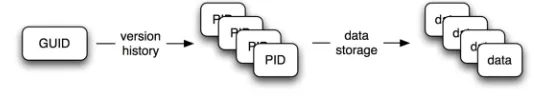
The generic storage layer provides a ubiquitous resilient mutable storage facility for unstructured data, with an historical record. To support the historical record, updates are appended rather than being destructive. The main entities supported are data blocks, PIDs, and GUIDs:
• A data block contains unstructured data. Blocks have arbitrary size and are immutable.
• A PID (Persistent Identifier) is used to denote a particular data block. This might correspond to a particular version of a file, a fragment of a file, or some other object.
[image:3.595.161.430.453.501.2]• A GUID (Globally Unique Identifier) is used to denote something with identity, such as a file or object.
Fig. 2. Logical entities in the generic storage layer
The main algorithms operating in the generic storage layer maintain two distributed services: the data storage service (mapping a PID to an immutable data block) and the version history service (mapping a GUID to a sequence of PIDs). In each case, the service is structured as a service endpoint communicating with a set of collaborating servers. Both services are required to be Byzantine-fault-tolerant [7].
2.1 Data Storage
generation function returns a set of keys that are evenly distributed in key space. The number of keys is determined by the data replication factor. Having located the replication nodes, referred to as the peer set for the data key, the service endpoint sends a copy of the data to each of the hosts. To achieve Byzantine fault tolerance, the storage operation completes once (r-f) nodes have replied indicating that they have successfully stored the data, where r is the replication factor and f is the maximum number of faulty nodes that can be tolerated. In common with all Byzantine fault tolerance schemes, r must be greater than 3f. This ensures that even if the
(r-f) replies include f misleading ones from faulty nodes, at least (f+1)
correctly functioning nodes have stored replicas of the data.
To retrieve a data block for a given PID, the replica nodes are located as above. It is then sufficient to pick a single replica node (at random, or guided by some ‘closeness’ metric) and request the data block from it. The secure hash function can then be used to verify that the block received does indeed correspond to the requested PID. If this check fails, another node can be tried.
2.2 Version History
The motivating example for this paper is provided by the commit protocol used to record a new GUID-PID mapping in the version history. The algorithm is executed by all members of the current peer set for the specified GUID; these are the nodes on which that GUID’s version history is replicated.
Peer set members are located in a similar manner to that already described for the data storage service. Since the addition of a new version to the version history is an update operation, it is necessary to operate a serialisation algorithm to ensure that a globally consistent view emerges in the face of concurrent updates. Otherwise, it would be possible for different members of the peer set for a given GUID to record different orderings in the version history. This means that it is necessary for the members of each peer set to maintain contact with one another, and to adjust their views of the set membership as the topology of the P2P network changes. When a request to store a new version is received by the members of a peer set they execute a commit protocol amongst themselves, only completing once all have agreed which is the next version to be recorded in the global history. Again, this protocol is tolerant of Byzantine nodes in the peer set.
On retrieval of a particular version, it is not possible for the service endpoint to verify the integrity of the result from any individual member of the peer set, since there are no constraints on what PID may be mapped to by a given GUID. It is thus necessary to compare the results as they arrive from the peer set members, and to select the (only possible) one that is returned consistently by at least f+1 nodes.
We now sketch the operation of the commit protocol1. To simplify peer
set maintenance, all members of a peer set have equal status, so that there is no need for a leader election process when membership changes. The
protocol is essentially a majority voting consensus algorithm, in which peer set members vote among potentially competing update requests for the GUID. The result is an agreed ordering of the requests among all peer set members. This agreed ordering is achieved as follows:
The protocol proceeds in two phases, involving the counting of vote
and commit messages among peer set members respectively. When a client issues an update for a particular GUID, a request is sent to all members of the peer set for that GUID. Each peer set member votes for particular updates in the order in which it receives the requests. Voting involves sending a vote message to all of the other members. Once a particular candidate update receives 2f+1 votes, all members agree that the update should be the next to be appended to the global history. This agreement is established by the exchange of commit messages. Consistent ordering arises since each committed update has been approved by a majority of the non-faulty members (of which there are between 2f+1 and
3f+1), and by allowing an update voted for by a sufficiently high number of other peer set members to proceed ahead of a previous locally selected update. Since there is no guarantee that any one of a set of concurrent updates will gain enough votes to reach this threshold, the algorithm may deadlock. It is thus necessary for the service endpoint to operate a timeout/retry scheme. Various schemes such as random or exponential back-off, or fixed or random server ordering, could be used to attempt to reduce the probability of repeated deadlocks.
The protocol is tolerant to Byzantine-faulty behaviour by members of the peer set, to the extent that at least 3f+1 members are needed to give tolerance to f failures. Hence for a replication factor r, yielding r replicas of each version history, the protocol tolerates at most floor((r-1)/3) faulty participants. Some examples of practical values for r and f are given in section 4.4.
Background processes regenerate missing replicas and replace faulty nodes, thus here the limit of f tolerable failures applies to the duration of a particular execution of the commit protocol, rather than to the lifetime of the system. Additional replicas need to be generated whenever the set of nodes storing replicas of a given data item is temporarily reduced. This may occur due to fail-stop faults, which are straightforwardly detected through timeouts, or due to the detection of malicious nodes. Such nodes are eventually detected, with high probability, using periodic cross-checks between replica nodes.
3
General Approach to State Machine Generation
3.1 Mapping Algorithm to State Machine
algorithm (about 500 lines of pseudo-code) nor the FSM (33 states with 3-4 transitions from each) is especially complex, they are non-trivial.
The original algorithm maintains the following variables for every ongoing commit operation:
• update_received: a flag recording whether an update request for the given update has been received
• votes_received: a count of vote messages received
• vote_sent: a flag recording whether a vote message has been sent • commits_received: a count of commit messages received
• commit_sent: a flag recording whether a commit message has been sent
• could_choose: a flag recording whether a future update could be voted for: this is false if another update is currently in progress • has_chosen: a flag recording whether the update currently in
progress was voted for locally.
The upper bound on both votes_received and commits_received is one less than the number of participants, which itself is given by the replication factor. Thus in total there are five boolean variables and two integer variables that range from 0 to r-1 for replication factor r.
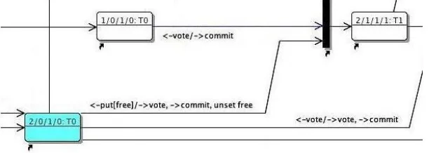
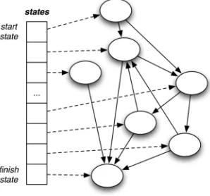
In the FSM model, each peer set member maintains a separate FSM instance for every ongoing update. Each instance encodes the possible values of the variables listed above in its states. For a replication factor of 4, there are 512 possible states, comprising all combinations of 5 boolean variables and 2 integer variables ranging from 0 to 3. Of these 512 states, only 33 are actually reachable in practice. Fig. 3 shows three states and some state transitions from our original state diagram2. The names of the
states encode the number of votes received, votes sent, commits received and commits sent. In the diagram, a transition from state 1/0/1/0 to 2/1/1/1
is triggered by the receipt of a vote message (labeled <-vote), since the threshold for committing has been reached (in this case 2 votes and 1
[image:6.595.148.454.514.623.2]commit received); the node sends a commit message and moves into the state 2/1/1/1.
Fig. 3. Excerpt from FSM for replication factor 4
2 The diagram was constructed at an early stage in the design process, at which
Even though we are satisfied (informally) that the FSM is correct, there is no strong correlation between the code and the FSM—thus its creation achieves little in terms of building confidence in the algorithm.
The main reason for the disparity between the FSM and the algorithm is that the former is specific to a fixed replication factor, while the algorithm is generic. The individual states in the FSM correspond to the counts of messages that have been sent and received at particular points during the algorithm’s execution. The maximum values of these counts are dependent on the replication factor, thus the number of states in the FSM is also dependent on the replication factor. This implies that it is not possible to construct a single FSM that is equivalent to the generic algorithm.
3.2 A Spectrum of Possible State Machines
In this approach, the process of transforming an algorithm to a FSM involves identifying particular ranges of values for the algorithm’s internal variables, and mapping them to states. A given range corresponds to an equivalence class, in the sense that the algorithm must behave identically for all values within that range, since it maps to a single state in the FSM.
In the commit algorithm described, each state in the FSM corresponds to a single value for each of the discrete (boolean and integer) variables. Thus the FSM encodes in its states all possible variable values. The original algorithm and the resulting FSM may be viewed as extremes on a spectrum trading off number of states against number of variables. The original algorithm has, effectively, one state and many variables, while the FSM has many states and no variables.
Intermediate points on this spectrum are also possible. For example, extended finite state machines (EFSMs) allow transitions and actions to depend on internal variables as well as states [2,3]. In an EFSM formulation of an algorithm, the original variable values that map to a given state are not restricted to an equivalence class, since the transitions and actions from that state may depend on the internal variables. This means that an EFSM typically has fewer states than a corresponding FSM.
For a given algorithm, a FSM is likely to be simpler in structure than an EFSM, but is more likely to suffer from state space explosion. The other significant difference is that a single EFSM may be used in place of a family of related FSMs. In the main part of this paper we focus on the use of FSMs; section 5.3 compares this with the use of EFSMs, and argues that the generative approach is also beneficial for EFSMs.
3.3 Generation Process
as the sending of messages to other participants in the distributed algorithm. We term the latter category of transitions phase transitions. By identifying where in the state diagram phase transitions occur, and relating these to the replication factor, it is possible to produce a generic description defining a family of related FSMs.
For our commit algorithm, we proceeded as follows:
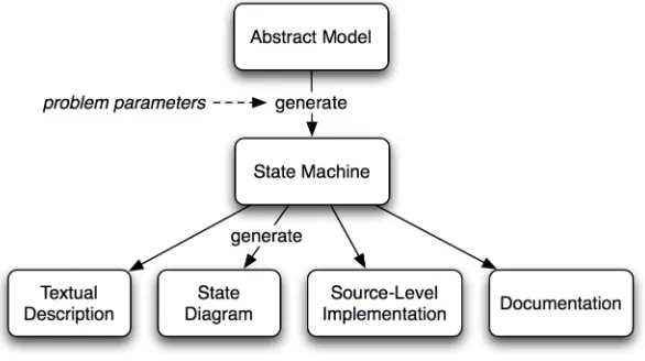
• We developed an abstract model that captured the common structure among the members of the FSM family.
• We executed the abstract model with a replication factor of 4 to generate an abstract representation of a specific FSM, which we then checked for consistency with the original FSM.
• Once satisfied with the correctness of the abstract model, we developed tools to generate various FSM artefacts, including diagrams and source-level implementations.
[image:8.595.152.445.322.486.2]The overall generation process is illustrated in Fig. 4.
Fig. 4. State machine generation scheme
class AbstractModel {
StateMachine generateStateMachine(int replication_factor); }
class StateMachine { String[] messages; State[] states; State start_state; State finish_state; }
class State {
String state_name; Transition[] transitions; String[] annotations; }
class Transition { State resultant_state; String[] actions; String[] annotations; }
Fig. 5. Corresponding Java classes
Fig. 6 shows an example of the use of these classes; the code fragment generates a particular FSM with replication factor 4, and uses another class, TextRenderer, to render it in a textual format.
AbstractModel abstract_model = new AbstractModel();
StateMachine machine_4 = abstract_model.generateStateMachine(4);
println(new TextRenderer().render(machine_4));
Fig. 6. Generating a FSM
3.4 Defining the Abstract Model
The abstract model is a model of the structure common to all members of the FSM family. The steps involved in the generation of a particular member of the family—an instance of StateMachine—are as follows:
1. generate a data structure containing representations of all possible states
2. for each state, generate the transitions resulting from all possible messages, and record in the data structure
3. prune any unreachable states 4. combine any sets of equivalent states
The final data structure forms the resulting StateMachine instance. Of these steps, 1, 3 and 4 can be performed fairly mechanically, whereas step
2 embodies the core logic of the algorithm.
Generating possible states. To generate all possible states, the state space must be defined in terms of the problem parameters—in our case, the replication factor. The state comprises the union of the 5 boolean and 2 integer variables listed in section 3.1. Hence the space of possible states, containing all combinations of values, has the size 25r2. This gives 512
states for the smallest sensible value of r=4. The generateStateMachine()
operation iterates through all of these combinations, generating a list of
Fig. 7. Data structure after step 1
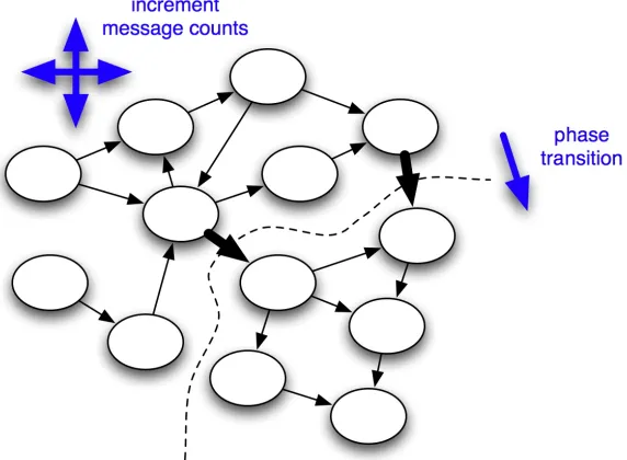
Generating transitions. The core of the abstract model defines the transitions between states. For any given state, it determines the effects of each of the possible messages, in terms of actions performed and the resulting state. Given that a state transition represents a change in the variables tracking the messages sent and received, a transition can be categorised as either a simple state transition or a phase transition.
On a simple state transition, the sole effect is to increment one of the received message counts; no action is performed. A phase transition occurs when the receipt of a message causes some threshold to be reached, triggering an action. For example, in the commit algorithm, when the total number of votes sent and received reaches the number of non-faulty nodes, a commit message is sent to all the nodes. Fig. 8 illustrates this distinction for an abstract state space: thin arrows show simple transitions, whereas thick arrows show phase transitions.
[image:10.595.155.441.477.687.2]The second step in the generation of a FSM is to iterate over each of the state representations in the data structure generated during the first step. For each state, the abstract model determines which transitions would result from each of the possible messages, if received by the running FSM in that state. Each transition, along with any corresponding actions, is recorded in the FSM data structure.
Fig. 9 shows an abstract representation of the entire abstract model, which defines how the FSM should react on receipt of each of the possible messages, depending on its current state. In each case the reaction is defined in terms of reads and writes to the state variables, and outgoing messages to be sent.
update message
set update_received
if could_choose and !has_chosen and vote_sent:
send vote message, set vote_sent, unset could_choose if total votes sent and received reaches threshold:
if commit_sent:
send commit message, set commit_sent set has_chosen
send not free message
vote message
increment corresponding count
if total votes sent and received reaches threshold: if !vote_sent:
if could_choose:
set has_chosen, send not free message
send vote message, set vote_sent, unset could_choose if commit_sent:
send commit message, increment count
commit message
increment corresponding count
if total commits received reaches threshold: if !vote_sent:
send vote message, set vote_sent, unset could_choose if commit_sent:
send commit message, set commit_sent if has_chosen:
send free finished
free message
if !vote_sent and !has_chosen: set could_choose
if update_received:
send vote message, set vote_sent, unset could_choose if total votes sent and received reaches threshold:
if !commit_sent:
send commit message, set commit_sent set has_chosen
send not free message
not free message
if !vote_sent and !has_chosen: unset could_choose
Fig. 9. Abstract model pseudo-code
The abstract model pseudo-code is now used as a guide to implementation. Fig. 10 shows the implementation of the operation
message3. The control decisions that would be taken dynamically in a
generic algorithm are here being taken at generation time.
void generateTransitionOnVote(State s) {
List<String> actions = new ArrayList<String>(); try {
State s1 = targetOnVoteReceived(s, actions); if (reachedNonFaultyThreshold(s1.getTotalVotes())) {
// Phase transition: vote threshold exceeded. if (!s1.getVoteSent()) {
if (s1.getCouldChoose()) {
s1 = targetOnHasChosenSet(s1, actions); s1 = targetOnNotFreeSent(s1, actions); }
s1 = targetOnVoteSent(s1, actions); }
if (!s1.getCommitSent()) {
s1 = targetOnCommitSent(s1, actions); }
}
s.recordTransition(Message.VOTE, actions, s1); }
catch (InvalidStateException e) {
// Ignore - message not applicable in this state. }
[image:12.595.152.400.153.336.2]}
Fig. 10. Implementation of part of abstract model
The list actions is used to accumulate representations of any outgoing messages to be sent as the full consequences of receiving the vote message are elaborated. Utility methods such as targetOnVoteReceived() and
targetOnVoteSent() simply calculate the state reached as a result of the corresponding state variable change. A series of updates to the state variable s1 generate all the required state variable changes following receipt of the vote message. Finally, the resulting state transition is recorded in the FSM representation of the current state, together with any necessary actions.
Fig. 11 shows the data structure after representations of the state transitions have been generated.
Fig. 11. Data structure after step 2
3Similar logic in the abstract model generates documentation describing the states
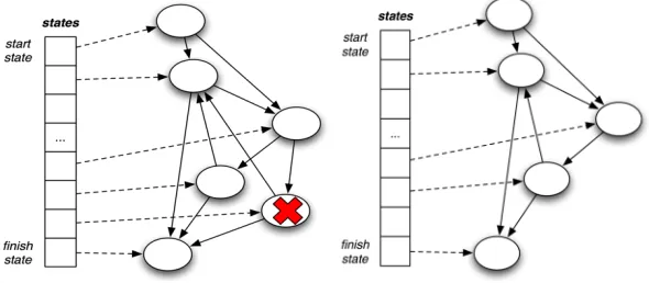
[image:12.595.223.372.502.641.2]Pruning unreachable states. Once the complete transition graph has been generated, a reachability analysis is performed. Depending on the application, there may exist states that could never be reached via transitions from the start state. For example, the commit algorithm completes as soon as f+1 commit messages have been received, thus there are no reachable states where the commit count exceeds f. For simplicity, such states are removed from the generated model. With a replication factor of 4, this step reduces the state space from its initial size of 512 to 48. Fig. 12 illustrates the result of pruning.
Fig. 12. Data structures before and after step 3
Combining equivalent states. The generated FSM may be further simplified by identifying and combining sets of states that are equivalent, in the sense that the outgoing transitions from each perform the same actions and lead to the same destination state. With a replication factor of 4, this process results in 33 states. Fig. 13 illustrates the result of this step.
[image:13.595.150.445.471.600.2]3.5 FSM Artefacts
The abstract representation of a FSM generated by the abstract model can be rendered to yield various concrete artefacts, including:
• a simple textual representation • a state transition diagram
• source code for an implementation of the corresponding protocol
Fig. 14 shows the textual representation of an example state and its outgoing transitions. The name of the state encodes the variable values (update_received, votes_sent etc) in that state. The commentary describing the state in terms of the generic algorithm is entirely automatically generated, derived from annotations specified within the abstract model implementation. These annotations were omitted from Fig. 10 for brevity; in the full code, each successive assignment to the state variable s1 is accompanied by a call to a method that records a textual annotation describing the reason for the change.
state: T/2/F/0/F/F/F --- Description:
Have received initial update from client.
Have not voted since another update has already been voted for. Have received 2 votes and no commits.
Have not sent a commit since neither the vote threshold (3) nor the external commit threshold (2) has been reached.
May not choose since another ongoing update has been voted for. Have not chosen this update since another ongoing update has been chosen.
Waiting for 1 further vote (including local vote if any) before sending commit.
Waiting for 2 further external commits to finish.
Transitions:
message: VOTE action: ->vote action: ->commit
transition to: T/3/T/0/T/F/F
message: COMMIT
transition to: T/2/F/1/F/F/F
message: FREE action: ->vote action: ->commit action: ->not free
transition to: T/2/T/0/T/T/T
Fig. 14. Example generated state description
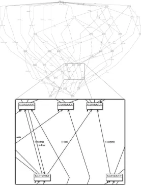
Fig. 15. Automatically rendered diagram of generated FSM
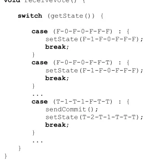
A FSM can also be rendered, automatically, as a source code implementation. Fig. 16 shows a fragment of generated code, comprising part of the handler method for incoming vote messages. Whenever a vote
message for a particular GUID/PID update is received by a peer set member, the receiveVote() method of the corresponding FSM instance is invoked.
The body of the handler message consists of a large case switch on the current machine state, with a branch for each possible state. Each state is represented by a generated variable of the form F-0-F-0-F-F-F, encoding the corresponding values of the state variables. Although the structure embodied in the generated code is equivalent to that shown in Fig. 14, its organisation differs in that all possible states are grouped under each message, rather than vice-versa.
actions are also performed—in this case, the sending of a commit message to the other members of the peer set. This corresponds to a phase transition.
void receiveVote() {
switch (getState()) {
case (F-0-F-0-F-F-F) : { setState(F-1-F-0-F-F-F); break;
}
case (F-0-F-0-F-F-T) : { setState(F-1-F-0-F-F-F); break;
} ...
case (T-1-T-1-F-T-T) : { sendCommit();
setState(T-2-T-1-T-T-T); break;
[image:16.595.151.299.169.333.2]} ... } }
Fig. 16. Example generated source code
Commentary on states and transitions, as illustrated in Fig. 14, is also included in the generated code.
4
Use in Practice
Having outlined our general approach to designing and implementing a distributed algorithm as a family of FSMs, we now discuss several practical issues:
• how to write a source code generator to produce an implementation from a FSM representation
• when to perform source code generation
• how to incorporate generated code into an application • the execution cost of generation
4.1 Writing Generative Code
Generative code, which produces a representation of new source code when executed, is often difficult to write and to understand. Typically, generative code involves either much hard-to-read string manipulation, or operations on an abstract syntax tree. In either case, discerning the intended structure of the generated code from the generator can be challenging.
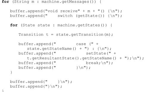
handler, a case switch over all states is generated—Fig. 16 illustrates one such handler.
for (String m : machine.getMessages()) {
buffer.append("void receive" + m + "() {\n"); buffer.append(" switch (getState()) {\n");
for (State state : machine.getStates()) {
Transition t = state.getTransition(m);
buffer.append(" case (" + state.getStateName() + ") : {\n"); buffer.append(" setState(" +
t.getResultantState().getStateName() + ");\n"); buffer.append(" break;\n");
buffer.append(" }\n"); }
[image:17.595.152.399.155.310.2]buffer.append(" }\n"); buffer.append("}\n"); }
Fig. 17. Generative code for state machine implementation
Such generative code is undoubtedly unwieldy. We have previously experimented with the development of GUI tools to assist with the construction of generative code [10]. Here we take a simpler approach, restricting ourselves to string manipulation, with a small set of utility methods to assist with legibility of both generative and generated code, as outlined in Fig. 18.
// Adds the specified items to the output buffer. void add(StringBuffer buffer, String... items);
// Adds the specified items to the output buffer, with newline. void addLn(StringBuffer buffer, String... items);
// Opens a new block and increases indent level. void enterBlock(StringBuffer buffer);
// Exits current block and decreases indent level. void exitBlock(StringBuffer buffer);
// Increases the indent level. void increaseIndent();
// Decreases the indent level. void decreaseIndent();
// Resets indentation. void resetIndent();
Fig. 18. Generation utility methods
for (String m : machine.getMessages()) {
addLn(buffer, "void receive" + m + "()"); enterBlock(buffer);
addLn(buffer, "switch (getState())"); enterBlock(buffer);
for (State state : machine.getStates()) {
Transition t = state.getTransition(m);
addLn(buffer, "case (" + state.getStateName() + ") :"); enterBlock(buffer);
addLn(buffer, "setState(" +
t.getResultantState().getStateName() + ");"); addLn(buffer, "break;");
exitBlock(buffer); }
[image:18.595.153.416.126.299.2]exitBlock(buffer); exitBlock(buffer); }
Fig. 19. Generative code using simple abstractions
It would also be possible for generative code to manipulate an abstract syntax representation. In practice, we have found that this yields less intelligible generative code.
4.2 When to Perform Generation
Given the ability to generate on demand an implementation of a FSM solution to a distributed algorithm, for a given parameter value, there are several options as to when such generation could be performed:
• once, during the initial development of the overall application of which the solution forms part
• every time the algorithm needs to be executed
• whenever a new value of the parameter is encountered
Clearly, the appropriate point on this spectrum depends largely on the degree to which the required parameter value varies. We have incorporated a generated FSM solution for the distributed commit
algorithm into the ASA infrastructure. Since the replication factor is expected to change only rarely, we executed the abstract model with the default replication factor, generated source code from the resulting FSM, and copied that into the code-base.
Should we wish in future to support dynamic change to the replication factor, this may be achieved by dynamically generating implementations on the fly. Since such changes are not expected to be frequent in the distributed storage application, the amortised cost of such regeneration should not be significant.
4.3 Incorporation of Generated Code
For one-off generation followed by copying and pasting into an existing code base, there is no real issue regarding incorporation of generated code into the surrounding application. Once added, the generated code is treated in exactly the same way as previously existing code during the build process.
For code generated on the fly, however, it is necessary to compile, load and bind to the resulting executable code dynamically. Various approaches have been used [11-13]; more recently, Java 6 has provided explicit run-time access to the compiler [14].
4.4 Execution Cost
[image:19.595.159.440.438.514.2]As indicated above, given the expected styles of use, the execution cost of generation is unlikely to be particularly important. Nonetheless, we performed a short series of measurements, for FSMs supporting various replication factors in our distributed storage application. The results are shown in Table 1, which lists the characteristics of FSMs of various complexities. The columns f and r show the degree of Byzantine-fault-tolerance and replication factor respectively. The next two columns show the numbers of states before and after pruning. The final column shows the approximate wall-clock times taken to generate the FSMs on an Apple MacBook Pro (3GB, 2.33GHz Intel Core 2 Duo).
Table 1. Times to generate state machines of various complexities
f r initial states final states generation time (s)
1 4 512 33 0.10
2 7 1568 85 0.12
4 13 5408 261 0.38
8 25 20000 901 2.2
15 46 67712 2945 19.1
The size of the initial state space, before pruning, is proportional to the square of r, the replication factor, since the state space encodes two independent variables with r legal values. The size of the final pruned state space appears to grow slightly slower than r2. The relationship
between state space size and generation time cannot be asserted with any confidence from this small sample. The pragmatic conclusion, however, is that generation time does not appear likely to be a limiting factor in the application of this technique.
5
Methodology
We conclude our discussion of this approach by summarising the key features, identifying a general methodology that could be applied to problems other than the original motivating distributed storage system, and speculating on the scope of such applicability.
5.1 A General Methodology
To recap, the main steps involved in the approach, which we have illustrated in the context of the commit algorithm, are:
• identify the core variables used in the algorithm, which in combination define the state space
• identify the messages that can be received by a FSM
• identify the phases intrinsic to the algorithm, and the actions that should result from phase transitions
• define an abstract model that captures the state transition logic • encode the above in the form of an abstract model implementation
that can be used to generate FSMs for various parameter values • define renderers to produce various concrete artefacts from an FSM
representation, the most important of which is a source code renderer that can generate specific FSM implementations
The resulting abstract model can then be used to produce implementations as required.
Since completing the abstract modelling process for the ASA distributed commit algorithm, as illustrated throughout the paper, we have refined the infrastructure to make it more generic, and thus applicable to other problems. Since much of the manipulation of FSM representations is independent of the details of the algorithm being modelled, the implementation of these steps was extracted into an abstract super-class. Problem-specific abstract models can be derived from this.
Rather than containing hard-wired definitions of the state components and messages, these are now represented by a data structure with which the generic abstract model is initialised. Fig. 20 shows how the abstract model for the commit algorithm is now configured. Each instance of
StateComponent[] state_components = { new IntComponent("votes_received", replication_factor - 1),
new IntComponent("commits_received", replication_factor - 1),
new BooleanComponent("update_received"), new BooleanComponent("vote_sent"), new BooleanComponent("commit_sent"), new BooleanComponent("could_choose"), new BooleanComponent("has_chosen")};
String[] messages = {"update", "vote", "commit", "free", "not_free"};
initAbstractModel(state_components, messages);
Fig. 20. Initialising generic abstract model
The source code renderer is now completely generic with respect to the algorithm being modelled, so it is possible to apply the methodology to new algorithms without writing any new generative code. The rendering code is parameterised with a class defining appropriate action methods, such as sendCommit() in Fig. 16. The generated class inherits from this specified class, allowing it to access the action methods.
5.2 Applicability of the Methodology
We believe that the technique of generating FSM families is applicable to a range of distributed applications that can be broadly characterised as
message counting algorithms. There are a number of different algorithms that may be characterised in this manner including consensus algorithms, distributed termination algorithms, distributed garbage collection algorithms, and threshold signature algorithms.
The algorithm with which we demonstrated the technique in this paper is essentially a consensus algorithm. Perhaps the best known consensus algorithm is that proposed by Chandra and Toueg [15]. In that algorithm, each of n processes counts rounds with a rotating coordinator. In each round, the participants and the coordinator exchange beliefs upon which they are trying to agree. Each process maintains three pieces of state: the actual decision, a counter storing the round number, a belief containing an estimate of the decision and the round number in which the decision was made. Like the algorithm described in this paper, the state held at each node and the messages themselves are relatively simple and amenable to being processed by a FSM.
A distributed computation may be defined as being terminated when each process in it has locally terminated and no messages are in transit. Alternately this may be defined as when the number of messages sent is equal to the number of messages received [16]. Consequently, most distributed termination algorithms are based upon message counting. Furthermore, the state carried in both the messages and held by the processes is relatively simple. We therefore believe that the techniques described in this paper may be applied to such algorithms.
reverse mapping, that is the combination of any known distributed termination algorithm with a centralised garbage collector to produce a distributed garbage collector. It is therefore unsurprising that we believe that the technique described here can also be applied to distributed garbage collection. However, the problems of doing so may outweigh the benefits. In [18] an algorithm called task balancing is described, in which each site counts (a) the number of tasks of each job sent by each site to each other site, and (b) the number of tasks received by and completed at each site. The encoding of such data structures in a FSM, even one that has been mechanically derived, may prove overly complex due to an explosion in the state space. In such cases, EFSMs may be useful, as discussed in the next section.
5.3 Generating Extended Finite State Machines
As mentioned briefly earlier, the process of mapping an algorithm to a state machine formulation can be thought of as involving a spectrum of target state machines. At one end of the spectrum lies the original algorithm, viewed as a state machine with a single state and multiple internal variables. At the other end lies the FSM or family of FSMs, with multiple states and no internal variables. At intermediate points lie various EFSMs, with a number of internal variables and fewer states than the FSMs. The designer selects an appropriate point on this spectrum through decisions on which variables in the original algorithm should be mapped to variables in the state machine, and which should be encoded in the state space.
The commit protocol can be implemented as an EFSM in which the message counting variables are mapped to EFSM variables. The effect is to coalesce the states within each state phase of the original FSM, so that all state transitions in the EFSM correspond to phase transitions in the FSM. For example, all of the FSM states that differ only in the number of
vote messages below the threshold become a single EFSM state. The resulting EFSM contains 9 states.
Besides the reduction in state space size, the other benefit of the EFSM formulation in this example is that the EFSM is generic with respect to the replication factor. Its states do not encode the values of the message counts, the possible values of which depend on the replication factor, but simply whether or not they have reached their respective thresholds. The state space of the EFSM is thus not dependent on the replication factor.
Nonetheless, it is not straightforward to construct the EFSM in this example. It appears that it may still be beneficial to use a similar approach to that outlined for FSMs, defining an abstract model and then generating an EFSM from it.
6
Related Work
computations with fixed numbers of states. EFSMs [2] permit greater flexibility, by allowing transitions to depend on internal variables.
[3] describes the generation of FSMs from abstract state machines, in which the states of an abstract state machine are grouped into hyperstates, corresponding to FSM states. The algorithm is approximate in that some links or states may be missing; since the method is targeted at very large state spaces this is an acceptable trade-off for tractability.
Architectural style languages [20,21] allow families of related systems to be characterised in terms of their shared high level system structure, and specialised to produce particular instances. The work described here is less general since it focuses explicitly on the FSM paradigm; the generic abstract model could be thought of as one particular architectural style.
We have previously used generative techniques to build generic object browsers [11] and to support highly generic strongly typed code [12].
An alternative strategy is to apply formal specification and verification techniques to fault-tolerant algorithms. For example, in [22] a protocol is specified as logical assertions and verified using an interactive proof checker. In [23] an extended actor algebra is used to specify fault-tolerant software architectures. These approaches offer the possibility of formal proofs, whereas here we intend to provide a less formal aid to understanding, at significantly lower cost.
7
Conclusions
We have outlined an approach to generating an EFSM, or a family of related FSMs, and corresponding protocol implementations from a unifying abstract model. In the ASA project this has allowed us to produce a FSM style description of our original BFT distributed commit algorithm. This has increased our confidence in the correctness of the algorithm; indeed several errors in the original version were identified during the process.
We have applied this approach to a specific BFT distributed algorithm, and believe the approach to be applicable to other critical infrastructure problems involving message-counting protocols where the number of states is dependent on a set of parameters.
8
Acknowledgments
9
References
1. Minsky, L.M.: Computation: Finite and Infinite Machines. Prentice Hall
(1967)
2. Cheng, K.T., & Krishnakumar, A.S.: Automatic Functional Test Generation
using the Extended Finite State Machine Model. In: 30th Design Automation Conference, Dallas, Texas. pp.86-91 ACM (1993)
3. Grieskamp, W., Gurevich, Y., Schulte, W., Veanes, M.: Generating Finite
State Machines from Abstract State Machines. ACM SIGSOFT Software Engineering Notes, 27,4:112-122 (2002)
4. Kirby, G.N.C., Dearle, A., Norcross, S.J., Tauber, M., Morrison, R.: Secure
Location-Independent Storage Architectures (ASA).
http://asa.cs.st-andrews.ac.uk/ (2004)
5. Dabek, F., Zhao, B.Y., Druschel, P., Kubiatowicz, J., Stoica, I.: Towards a
Common API for Structured Peer-to-Peer Overlays. In: 2nd International Workshop on Peer-to-Peer Systems (IPTPS '03), Berkeley, CA, USA. (2003)
6. Stoica, I., Morris, R., Karger, D., Kaashoek, F., Balakrishnan, H.: Chord: A
Scalable Peer-to-Peer Lookup Service for Internet Applications. In: ACM SIGCOMM 2001, San Diego, CA, USA. pp.149-160 (2001)
7. Lamport, L., Shostak, R., Pease, M.: The Byzantine Generals Problem. ACM
Transactions on Programming Languages and Systems, 4,3:382-401 (1982)
8. Eastlake, D., & Jones, P.: RFC 3174 - US Secure Hash Algorithm 1 (SHA1).
http://www.faqs.org/rfcs/rfc3174.html (2001)
9. Borland: Borland Together. http://www.borland.com/us/products/together/
(2007)
10. Kirby, G.N.C., Connor, R.C.H., Morrison, R.: START: A Linguistic Reflection Tool using Hyper-Program Technology. In: Persistent Object Systems: 6th International Workshop on Persistent Object Systems (POS6), Tarascon, France. Workshops in Computing pp.355-373 Springer-Verlag (1994)
11. Dearle, A., & Brown, A. L.: Safe Browsing in a Strongly Typed Persistent Environment. Computer Journal, 31,6:540-544 (1988)
12. Kirby, G. N. C., Morrison, R., Stemple, D. W.: Linguistic Reflection in Java. Software - Practice & Experience, 28,10:1045-1077 (1998)
13. Kirby, G.N.C.: Dynamic Java Compiler.
http://www-systems.cs.st-andrews.ac.uk/wiki/Dynamic_Java_Compiler (2005)
14. Sun Microsystems: JavaCompiler Interface.
15. Chandra, T., & Toueg, S.: Unreliable Failure Detectors for Reliable Distributed Systems. Journal of the ACM, 43,1:225-267 (1996)
16. Mattern, F.: Algorithms for Distributed Termination Detection. Distributed Computing, 2,3:161-175 (1987)
17. Tel, G., & Mattern, F.: The Derivation of Distributed Termination Detection Algorithms from Garbage Collection Schemes. ACM Transactions on Programming Languages and Systems, 15,1:1-35 (1993)
18. Blackburn, S.M., Hudson, R.L., Morrison, R., Moss, J.E.B., Munro, D.S., Zigman, J.N.: Starting with Termination: A Methodology for Building Distributed Garbage Collection Algorithms. In: 24th Australasian Computer Science Conference (ACSC2001), Gold Coast, Queensland. pp.20-28 (2001)
19. Brand, D., & Zafiropulo, P.: On Communicating Finite-State Machines. Journal of the ACM, 30,2:323-342 (1983)
20. Garlan, D., Allen, R.J., Ockerbloom, J.: Exploiting Style in Architectural Design Environments. In: 2nd ACM SIGSOFT Symposium on Foundations of Software Engineering, New Orleans, Louisiana, USA. pp.175-188 (1994)
21. Medvidovic, N., & Taylor, R. N.: A Classification and Comparison Framework for Software Architecture Description Languages. IEEE Transactions on Software Engineering, 26,1:70-93 (2000)
22. Hooman, J.: Verification of Distributed Real-Time and Fault-Tolerant Protocols. In: 6th International Conference on Algebraic Methodology and Software TechnologyLecture Notes in Computer Science 1349 pp.261-275 Springer (1997)
23. Dragoni, N., & Gaspari, M.: An Object Based Algebra for Specifying a Fault Tolerant Software Architecture. Journal of Logic and Algebraic