Author’s Accepted Manuscript
A new measuring method for friction factor by
using ring with inner boss compression test
Chengliang Hu, Qiang Yin, Zhen Zhao, Hengan Ou
PII:
S0020-7403(16)30819-0
DOI:
http://dx.doi.org/10.1016/j.ijmecsci.2017.01.042
Reference:
MS3581
To appear in:
International Journal of Mechanical Sciences
Received date: 18 November 2016
Revised date:
6 January 2017
Accepted date: 23 January 2017
Cite this article as: Chengliang Hu, Qiang Yin, Zhen Zhao and Hengan Ou, A
new measuring method for friction factor by using ring with inner boss
compression
test,
International
Journal
of
Mechanical
Sciences,
http://dx.doi.org/10.1016/j.ijmecsci.2017.01.042
This is a PDF file of an unedited manuscript that has been accepted for
publication. As a service to our customers we are providing this early version of
the manuscript. The manuscript will undergo copyediting, typesetting, and
review of the resulting galley proof before it is published in its final citable form.
Please note that during the production process errors may be discovered which
could affect the content, and all legal disclaimers that apply to the journal pertain.
A new measuring method for friction factor by using ring with inner boss compression
test
Chengliang Hua, Qiang Yina, Zhen Zhaoa*, Hengan Oub
a
Institute of Forming Technology & Equipment, Shanghai Jiaotong University, Shanghai 200030, China
b
Department of Mechanical, Materials and Manufacture Engineering, University of Nottingham, Nottingham NG7 2RD,
UK
*
Corresponding author. Institute of Forming Technology & Equipment, Shanghai Jiaotong University, Shanghai 200030, China. Tel.: +86 2162813430-8116. [email protected].
Abstract
To overcome the disadvantage of the bulging effect due to non-uniform deformation in dimension measurement of the
conventional ring compression test (RCT), a new measuring method for the friction factor called ring compression test
with inner boss (RCT-IB) was proposed. The compression behavior of the ring with an inner boss was investigated and
results showed that the change of inner boss was sensitive to friction. The non-concave profile of inner boss allows the
dimensional changes to be easily and precisely measured. The calibration curves of RCT-IB were constructed and
compared with those of RCT showing similar level of sensitivities at most friction conditions. The RCT-IB method was
successfully used to measure the friction factors under four different lubricating conditions.
Keywords
Friction factor; Ring compression test; Ring compression test with inner boss; Calibration curves
1. Introduction
Friction at the tool-workpiece interface has significant effects on the metal flow, forming load, surface quality and tool
processes using commercial or in-house codes. Therefore, the friction condition mostly defined by the friction factor
should be quantitatively assessed in the design and evaluation of metal forming processes. The ring compression test
(RCT), which was firstly proposed by Kunogi [1] and further developed by Male and Cockcroft [2], has been one of the
most commonly used method for characterizing friction conditions in bulk forming operations [3], and is still actively
used in recent research works of forging area [4-6].
In the ring compression test, the change of the inner diameter (ID) is sensitive to friction, and the correlation between
the change of the ID and the reduction of height under different friction conditions is defined by a set of calibration
curves. Different from calibration curves derived from experimental testing [2], the theoretical calibration curves were
constructed by analyzing the ring compression on the assumption of uniform deformation using an optimum upper
bound method [7] and a stress analysis approach [8]. Although the accuracy was improved by introducing small
deformation increments [9], the theoretical data still did not agree well with the results obtained from experiments.
Due to non-uniform deformation, the bulging effect in the ring compression is an important factor that affects the
accuracy of measurement in conventional RCT. Based on the assumption of average flow stress at each small
deformation step, the parameter representing the severity of the bulge could be determined from the condition that the
total energy-dissipation rate should be minimum, as proposed by [10]. By using a simple parabolic curve with one
uncertain coefficient [11] and with two unknown coefficients [12] the specific friction coefficients were determined
using different theoretical calculation methods to describe the bulge profile with improved correlation of the calibration
curves to the experimental results.
However, there are many factors that affect the accuracy of the calibration curves, and it is extremely difficult if not
impossible to construct calibration curves purely based on theoretical analysis methods. In the past two decades, the
finite element (FE) method becomes commonly applied in numerical simulation of metal forming processes. The
property, strain-rate sensitivity, and barreling [15] on the calibration curves were investigated in detail, which led to a
general observation that it is not preferable to try to use generalized calibration curves regardless of the material type
and test conditions for different metal forming processes [15]. Therefore, Shahriari, et al. [16] and Mirahmadi, et al. [17]
tried to develop their own calibration curves for hot forging of nimonic 115 superalloy and Ti-6Al-4V under the
specific temperature and strain rate range.
In addition to a group of sound calibration curves, the measurements of the ring dimensions before and after RCT
testing also have a significant effect on the determined friction factor. Originally, a profile projector and a planimeter
was used to obtain the mean diameter of the slightly non-circular shape upon deformation [2]. For convenience, using
only a caliper the ID was measured in two directions at right angles [18]. Another method designed to measure the ID
by placing a ball-bearing of known diameter onto the specimen was proposed by Hartley, et al. [19]and the ID can be
calculated on the assumption of the deformed profile as a circle shape through two height dimensions accurately
measured using a standard micrometer. In reality, there are many possible profiles of the ID after inhomogeneous
deformation [17, 20], which results in a seemingly simple task quite difficult to precisely capture the change of the ID
from the conventional RCT.
To overcome the above limitations in conventional RCT, an alternative method to evaluate the friction conditions
named as RCT-B (ring compression test with an outer boss) was proposed by the authors [21], where the ring with an
outer boss was used to substitute the typical ring specimen in compression test. The RCT-B method allows the outer
diameter of boss to be measured easily and precisely, which enables more accurate measurement of friction conditions,
and can be quantitatively evaluated the different lubricating effects by simply investigating the inclined angle of the
outer boss. However, its sensitivity decreases significantly compared with conventional RCT when the friction factor is
larger than 0.5.
simulation. Based on the analysis results, another measuring method of friction factor by using ring with inner boss
compression test (RCT-IB) was proposed, which could be used as a complementary way to determine the friction factor
in bulk forming. In the following sections, the raw material property tests, compression experimental works and
corresponding FE simulations are first carried out to investigate the compression behavior of a ring with inner boss. In
Section 3, according to the FE simulation results the calibration curves of the RCT-IB are constructed and compared with the
calibration curves of conventional RCT. In Section 4, more experimental tests are performed to validate the RCT-IB
method, and the evaluation and discussion of the friction conditions obtained from both the RCT-IB and RCT methods
are given in detail. Finally, the conclusions drawn from this research are summarized in Section 5.
2. Compression behavior of ring with an inner boss
In this study, the proposed geometry of ring with inner boss is shown in Fig.1. The outer diameter of the specimen is
35.0 mm and the inner diameter 20.0 mm, and the height is 10.0 mm, and the thickness and width of the inner boss is
1.6 mm and 2.0 mm, respectively. These dimensions lead to a ratio of outer diameter to inner diameter and to height to
be 7:4:2 with the height of the inner boss to be 16% of the height of the ring. The above dimensions rather than the
recommended ones for conventional RCT are chosen so as to ensure sufficient height reduction of the ring with an
inner boss in compression.
f35mm
f16mm
1
.6
mm 10
mm
f20mm
Fig. 1 The ring with inner boss
C45 steel, commonly used for automotive applications, is selected as the material of ring specimens. The main
chemical composition (wt.%) of the material is 0.46C, 0.33Si, 0.77Mn, 0.18Cr, 0.04Ni, 0.013P, and 0.015S. To improve
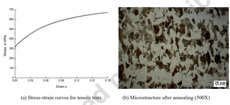
the cold forgeability, the hot-rolled raw material was annealed before compression test. The uniaxial tensile tests were
carried out to obtain the stress-strain curves, as shown in Fig.2 a). The elastic modulus E and yield stress s can be
determined to be 205GPa and 307.6 MPa. Considering the feature of stress-strain curves, a simple power law =s +
Kn can be used to model the flow stress behavior with the flow stress constant K to be 890.0 MPa and the strain
hardening exponent n to be 0.501. In addition, the microstructure after annealing was also investigated as shown in
Fig.2 b), and the Rockwell-B hardness was measured between 81.2 HRB and 82.0 HRB.
0.00 0.03 0.06 0.09 0.12 0.15 0.18 0
100 200 300 400 500 600 700
St
re
ss
MPa
Strain
(a) Stress-strain curves for tensile tests (b) Microstructure after annealing (500X)
Fig. 2 Stress-strain curves and microstructure of the annealed C45.
All specimens were machined to the dimensions presented in Fig. 1. After turning and grinding, the specimens were
shot blasted to keep similar surface finish with measured surface roughness between Ra 4.5 µm and Ra 5.5 µm, as
shown in Fig. 3. At the same time, the polished flat tools with surface roughness around Ra 0.06 µm were also
[image:6.595.99.495.315.497.2]Fig. 3 Specimen of ring with an inner boss
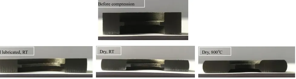
A series of RCT-IB tests were carried out on a 4000 kN hydraulic press. To create different friction conditions,
oil-lubricated specimens at room temperature, dry specimens at room temperature and dry specimens preheated to a
high temperature of 800oC were compressed between the flat tools. To facilitate observation, some specimens were cut
into half along the meridional plane, and the results were illustrated in Fig.4. For the oil-lubricated specimen at low
friction condition, the diameter of the inner boss (IB) of the ring is expanded after deformation, and the outer profile of
specimen is only slightly bugled; For the dry specimen at room temperature with a high friction condition, the diameter
of IB of the ring is shrunk after compression. The effect of bulging to form a convex shape of the outer profile of the
specimen becomes more significant. For the dry specimen deformed at 800oC to generate a high friction condition, the
IB is reduced significantly and the thickness of the inner boss is also increased. This results in significant bulging at the
outer profile of the specimen. In general, the compression behavior is similar to the traditional ring compression which
indicates that the dimensional changes of the inner boss are also sensitive to friction conditions. There are two
additional observations: first, the inner boss does not deform and the edge keeps straight in all compression conditions;
second, the thickness of the inner boss is increased under high friction conditions.
Oil lubricated, RT Dry, RT Dry, 800oC
Fig. 4 Different deformation modes in the compression of ring with inner boss
2.2 FE simulation
For further investigation, a 2D axisymmetric mechanical model is developed to simulate the compression process of
ring with inner boss at room temperature. In the FE model, the thermal effect is ignored because of the deformation is at
a temperature of 20oC, the elastic effect was calculated by using an elastic-plastic material model with an elastic
modulus of 205 GPa and a poisson’s ratio of 0.3, the shear friction law is used to define the friction conditions, and
1980 full integration quad elements with an edge size of 0.2 mm is meshed for the initial specimen. No remeshing is
triggered during the simulation to keep the number of each node as constant, which will facilitate the subsequent
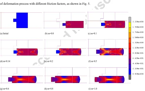
extraction of the node data from the simulation results. The strain distributions are extracted from the simulation results
of deformation process with different friction factors, as shown in Fig. 5.
(a) Initial (b) m=0.0 (c) m=0.1
(d) m=0.14 (e) m=0.2 (f) m=0.5
[image:8.595.45.537.355.663.2](g) m=0.6 (h) m=0.8 (i) m=1.0
Fig. 5 Equivalent plastic strain distribution of workpiece after 55% height reduction at different friction condition: (a) Initial; (b) m=0.0; (c)
When the friction factor is 0.0, the material uniformly flows outward. Separated by the inner boss, two short concave
profiles of the inner diameter (ID) of the ring occur with the increase of height reduction. It is different from that of
conventional ring compression where there is only uniform deformation and no bulge of ID. When the friction factor is
0.1, non-uniform deformation takes place and the outer diameter (OD) of the ring is bugled to form a convex profile,
the level of the concave profile of the ID is reduced because of the increased friction at the interface that resists the
outward flow of material. When the friction factor reaches 0.14, the degree of bulging of the OD of the ring increases
and the convex shape of the ID of the ring almost disappears. There is little change of the dimension or position of the
IB at the end of deformation, as shown in Fig.5 d). Under low friction conditions, both the IB and ID of the ring are
expanded, similar to the change of ID in ring compression.
When the friction factor is 0.2, two convex profiles separated by the inner boss are formed at the ID of the ring. With
the increase of friction factor, the degree of the convex profile in the ID and OD of the ring become more apparent. The
thickness of the inner boss is also increased with the friction factor. Furthermore, there is almost no deformation at the
inner boss even when the friction factor increases to 0.5, as the equivalent plastic strain in the zone of the inner boss is
close to 0, as shown in Figs5 a) - f). Essentially, the internal diameter of the inner boss keeps straight with height
reduction when the friction factor is lower than 0.5. This would make its dimension very easy to be precisely measured.
After the friction factor is further increased, the non-uniform plastic deformation of the ring becomes more obvious, as
shown in Figs 5 g) - i). Plastic deformation also takes place at the inner boss with an enlarged thickness and the internal
diameter of the IB is reduced gradually. There is an increased tendency of the convex profile of the IB with increased
friction factor. As there is no concave profile to be formed at the internal diameter of the inner boss, it makes the
internal diameter of the IB to be more easily measured.
3. Calibration curves of the RCT-IB method
with inner boss and easy for measurement, the compression of ring with inner boss (RCT-IB) can be used a favorable
method for measuring friction conditions in bulk metal forming. Therefore, a series of calibration curves are necessary
to allow the determination of friction factors under different friction conditions.
To construct the calibration curves of the RCT-IB method, the displacement of the node at the middle of the inner boss
and one node at the top edge are extracted from simulation results. These displacement data can reflect the change of
the internal diameter of the inner boss and the height of the specimen under deformation. The reduction in the internal
diameter of the inner boss after deformation is calculated as RIB = (db0-db1)/db0 and the reduction in height is calculated
as RH = (H0-H1)/H0, as shown in Fig.6. By conducting a series of FE simulations under different friction conditions and
extracting the above dimensional changes of the ring, the specific calibration curves for the proposed RCT-IB method
can be obtained, as shown in Fig. 7.
H0 H 1 d0 db0 db1
Fig.6 Changes in dimensions of ring with inner boss
0 10 20 30 40 50 60
-50 -40 -30 -20 -10 0 10 20 30 40 50 60 70
0 10 20 30 40 50 60
-50 -40 -30 -20 -10 0 10 20 30 40 50 60 70
0 10 20 30 40 50 60
-50 -40 -30 -20 -10 0 10 20 30 40 50 60 70
0 10 20 30 40 50 60
-50 -40 -30 -20 -10 0 10 20 30 40 50 60 70
0 10 20 30 40 50 60
-50 -40 -30 -20 -10 0 10 20 30 40 50 60 70
0 10 20 30 40 50 60
-50 -40 -30 -20 -10 0 10 20 30 40 50 60 70
0 10 20 30 40 50 60
-50 -40 -30 -20 -10 0 10 20 30 40 50 60 70
0 10 20 30 40 50 60
-50 -40 -30 -20 -10 0 10 20 30 40 50 60 70
0 10 20 30 40 50 60
-50 -40 -30 -20 -10 0 10 20 30 40 50 60 70
0 10 20 30 40 50 60
-50 -40 -30 -20 -10 0 10 20 30 40 50 60 70
0 10 20 30 40 50 60
-50 -40 -30 -20 -10 0 10 20 30 40 50 60 70
0 10 20 30 40 50 60
-50 -40 -30 -20 -10 0 10 20 30 40 50 60 70 R ed u ct io n i n i n te rn al d ia met er o f in n er b o ss (%)
Reduction in height(%)
Fig. 7 Calibration curves for RCT-IB
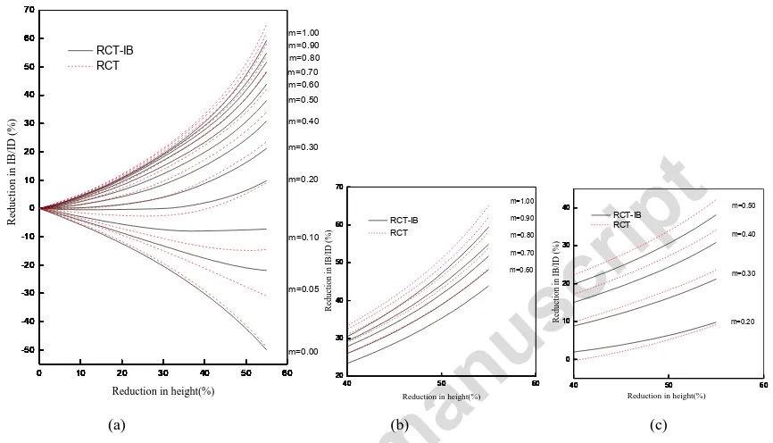
At the same time, the calibration curves for the conventional RCT have been created based on the reduction of the inner
diameter at the middle of the conventional ring specimen. To compare the similarities and differences of the calibration
curves from the RCT-IB and conventional RCT methods, the two sets of calibration curves are superimposed in Fig. 8.
0 10 20 30 40 50 60
-50 -40 -30 -20 -10 0 10 20 30 40 50 60 70
0 10 20 30 40 50 60
-50 -40 -30 -20 -10 0 10 20 30 40 50 60 70
0 10 20 30 40 50 60
-50 -40 -30 -20 -10 0 10 20 30 40 50 60 70
0 10 20 30 40 50 60
-50 -40 -30 -20 -10 0 10 20 30 40 50 60 70
0 10 20 30 40 50 60
-50 -40 -30 -20 -10 0 10 20 30 40 50 60 70
0 10 20 30 40 50 60
-50 -40 -30 -20 -10 0 10 20 30 40 50 60 70
0 10 20 30 40 50 60
-50 -40 -30 -20 -10 0 10 20 30 40 50 60 70
0 10 20 30 40 50 60
-50 -40 -30 -20 -10 0 10 20 30 40 50 60 70
0 10 20 30 40 50 60
-50 -40 -30 -20 -10 0 10 20 30 40 50 60 70
0 10 20 30 40 50 60
-50 -40 -30 -20 -10 0 10 20 30 40 50 60 70
0 10 20 30 40 50 60
-50 -40 -30 -20 -10 0 10 20 30 40 50 60 70
0 10 20 30 40 50 60
-50 -40 -30 -20 -10 0 10 20 30 40 50 60 70
0 10 20 30 40 50 60
-50 -40 -30 -20 -10 0 10 20 30 40 50 60 70
0 10 20 30 40 50 60
-40 -20 0 20 40 60
0 10 20 30 40 50 60
-40 -20 0 20 40 60
0 10 20 30 40 50 60
-40 -20 0 20 40 60
0 10 20 30 40 50 60
-40 -20 0 20 40 60
0 10 20 30 40 50 60
-40 -20 0 20 40 60
0 10 20 30 40 50 60
-40 -20 0 20 40 60
0 10 20 30 40 50 60
-50 -40 -30 -20 -10 0 10 20 30 40 50 60 70
0 10 20 30 40 50 60
-50 -40 -30 -20 -10 0 10 20 30 40 50 60 70
0 10 20 30 40 50 60
-50 -40 -30 -20 -10 0 10 20 30 40 50 60 70
0 10 20 30 40 50 60
-50 -40 -30 -20 -10 0 10 20 30 40 50 60 70
0 10 20 30 40 50 60
-50 -40 -30 -20 -10 0 10 20 30 40 50 60 70 RCT-IB R ed u ct io n i n I B /I D ( %)
Reduction in height(%)
m=0.20 m=0.10 m=0.05 m=0.00 m=0.90 m=1.00 m=0.80 m=0.70 m=0.60 m=0.50 m=0.40 m=0.30 RCT
40 50 60
20 30 40 50 60 70
40 50 60
20 30 40 50 60 70
40 50 60
20 30 40 50 60 70
40 50 60
20 30 40 50 60 70
40 50 60
20 30 40 50 60 70
40 50 60
20 30 40 50 60 70
40 50 60
20 30 40 50 60 70
40 50 60
20 30 40 50 60 70
40 50 60
20 30 40 50 60 70
40 50 60
20 30 40 50 60 70 RCT-IB R ed u ct io n i n I B /I D ( %)
Reduction in height(%) m=0.90 m=1.00 m=0.80 m=0.70 m=0.60 RCT
40 50 60
0 10 20 30 40
40 50 60
0 10 20 30 40
40 50 60
0 10 20 30 40
40 50 60
0 10 20 30 40
40 50 60
0 10 20 30 40
40 50 60
0 10 20 30 40
40 50 60
0 10 20 30 40
40 50 60
0 10 20 30 40 RCT-IB R ed u ct io n i n I B /I D ( %)
Reduction in height(%)
RCT
m=0.30
m=0.20 m=0.40 m=0.50
[image:11.595.80.513.200.448.2](a) (b) (c)
Fig. 8 Superimposed calibration curves of RCT and RCT-IB:(a) Whole chart; (b) Partially enlarged view of friction factors between m=0.6
to m=1.0; (b) Partially enlarged view of friction factors between m=0.2 to m=0.5
As shown in Fig. 8, the calibration curves of the RCT-IB method are similar to those of the conventional RCT method.
From the enlarged view of friction factors between m=0.6 and m=1.0, there is an obvious even spacing and at the same
time a degree of shift between the two groups of calibration curves from both RCT-IB and conventional RCT
conditions. This gives a clear indication that the RCT-IB and conventional RCT methods have similar sensitivities in
responding different friction conditions with its value from 0.6 to 1.0. As shown in Fig. 8 c), when the friction factors
are between m=0.2 and m=0.5, the reduction of internal diameter of the inner boss in RCT-IB is less sensitive than that
of the inner diameter change of the ring in the conventional RCT. While the sensitivity of the RCT-IB method is slightly
factor is less than 0.1. This would be clearly an advantage in measuring friction conditions at very low friction
conditions in metal forming.
4. Testing results and discussion
To further evaluate the proposed RCT-IB as an effective and robust method that can be used to measure friction
conditions in bulk forming, more compression tests were carried out with both the conventional RCT rings and the
RCT-IB rings with an inner boss. The conventional RCT ring specimens with a ratio of 6:3:2 widely-used in ring
compression test were prepared, and the nominal dimensions of the outer diameter, inner diameter and height are 36.00
mm, 18.00 mm and 12.00 mm, respectively. The compression tests between the flat tools with polished working surface
were performed on the 4000 kN hydraulic press at a speed of 5 mm/s under room temperature.
During the experimental tests, three different lubricants were adopted. A group of specimens were treated by the typical
zinc phosphate coating plus soaping process commonly used in cold forging of steel, the gray soap in the conversion coating
adhesion to the specimen could work as a lubricant, as shown in Fig.9 a). A liquid lubricant fortified with molybdenum
disulfide (MoS2) was chosen, and it can be directly sprayed and form a dry lubricating film in dark color on the
specimen, as shown in Fig.9 b). A heavy-duty oil free of chlorine with a viscosity (40oC) of 40 mm2/s was also selected,
and the specimen was dipped into an oil can before compression. To remove the effect of remaining residual lubricants,
Fig. 9 Lubricated specimens: (a) phosphate coating plus soaping; (b) molybdenum disulfide. (a) Phosphate coating plus soaping (b)
Molybdenum disulfide
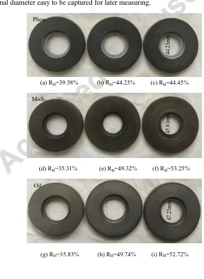
Fig. 10 shows the compressed rings with an inner boss under three lubricating conditions as mentioned above and
another case without any lubrication after compressed and at different height reduction between 34.96% and 53.25%.
Under dry condition, the rough end surfaces of the blasted specimen shown in Fig.10 j) becomes more smooth after
compressed between the polished tools, as shown in Fig.10 k). The new generated surfaces try to succeed the surface
feature from the shine tools. But some slightly local scratches appear on the end surfaces when the reduction in height
becomes larger, as shown in Fig.10 l). The tools are very easy to damage under large deformation without lubrication.
The inner boss of all specimens after compression still keeps in circular shape even when the reduction in height
reaches 53.25%. It is observed that the internal diameter of the inner boss can keep straight during the compression test,
resulting in the internal diameter easy to be captured for later measuring.
(a) RH=39.58% (b) RH=44.23% (c) RH=44.45%
(d) RH=35.31% (e) RH=49.32% (f) RH=53.25%
(g) RH=35.83% (h) RH=49.74% (i) RH=52.72%
4
7
.2
3
mm
4
5
.8
1
mm
4
4
.2
3
mm
Phos
MoS2
[image:13.595.131.428.364.770.2](j) RH=0.0% (k) RH=34.96% (l) RH=44.51%
Fig. 10 The ring with inner boss after compression under different lubricating conditions
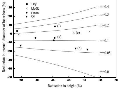
For the RCT-IB tests, the internal diameter of the inner boss and the height of each specimen before and after
compression were measured using a digital Vernier caliper, and each dimension was obtained from the average of three
measurements. The reduction in the internal diameter of the inner boss and the reduction in height were calculated, the
friction factors under four different lubricating conditions were determined based on the calibration curves presented in
Fig. 7. As shown in Fig.11, the averaged friction factors of phosphate coating plus soaping, molybdenum disulfide film,
heavy-duty oil lubrication and dry condition were 0.12, 0.17, 0.06 and 0.26, respectively. For further observation, four
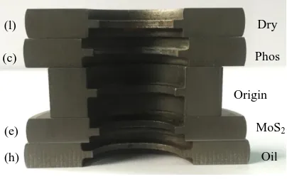
selected specimens of ring with inner boss after deformation including sample c, e, h and l illustrated in Fig.10 were cut
into halves, as shown in Fig.12. The internal diameter of the inner boss of dry condition (sample l) and MoS2 film
(sample e) were reduced as compared to the original one without deformation, whilst the internal diameter of the inner
boss with phosphating and soaping (sample c) and oil lubrication (sample h) were enlarged because of good lubrication
conditions with a friction factor less than m=0.14. These trends of the internal diameter changes of the inner boss
showed a good agreement with the above FE simulation results as shown in Fig. 5.
36 40 44 48 52 56 60
-50 -40 -30 -20 -10 0 10 20 30 40
36 40 44 48 52 56 60
-50 -40 -30 -20 -10 0 10 20 30 40
36 40 44 48 52 56 60
-50 -40 -30 -20 -10 0 10 20 30 40
36 40 44 48 52 56 60
-50 -40 -30 -20 -10 0 10 20 30 40
36 40 44 48 52 56 60
-50 -40 -30 -20 -10 0 10 20 30 40
36 40 44 48 52 56 60
-50 -40 -30 -20 -10 0 10 20 30 40
36 40 44 48 52 56 60
-50 -40 -30 -20 -10 0 10 20 30 40
36 40 44 48 52 56 60
-50 -40 -30 -20 -10 0 10 20 30 40
36 40 44 48 52 56 60
-50 -40 -30 -20 -10 0 10 20 30 40
36 40 44 48 52 56 60
-50 -40 -30 -20 -10 0 10 20 30 40 Phos R edu ct io n i n i n tern al d iame ter o f in n er b o ss (%) Oil
[image:14.595.194.398.599.752.2]Fig. 11 Experimental data points on the calibration chart of RCT-IB tests
Fig. 12 Sectioned specimens of RCT-IB tests
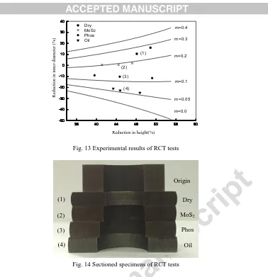
For the tests of the conventional RCT rings, both the initial and deformed dimensions of inner diameter and height in
each specimen were also measured. The corresponding reductions of the inner diameter and the height of the
conventional RCT rings were also calculated. The obtained results were plotted on the calibration chart of the
conventional RCT method, as shown in Fig.13, leading to the friction factors of phosphating plus soaping, MoS2 film,
oil and dry friction conditions to be determined as 0.13, 0.20, 0.055 and 0.27, respectively. From the sectioned
conventional RCT ring specimens after compression as illustrated in Fig.14, the inner diameter with oil lubrication
(sample 4) was enlarged significantly. The inner diameter with phosphating plus soaping (sample 3) was also enlarged
and a concave profile formed. A concave profile of the ring specimen with MoS2 film (sample 2) was formed from an
shrunk inner diameter. The inner diameter under dry condition (sample 1) was reduced and a slightly convex profile
was shaped. And the above observations of changed shape and dimensions of the conventional RCT ring specimens are
in a good agreement with the FE simulation results [14].
Dry
Phos
Oil MoS2
(l)
(c)
(h) (e)
36 40 44 48 52 56 60 -50 -40 -30 -20 -10 0 10 20 30 40
36 40 44 48 52 56 60
-50 -40 -30 -20 -10 0 10 20 30 40
36 40 44 48 52 56 60
-50 -40 -30 -20 -10 0 10 20 30 40
36 40 44 48 52 56 60
-50 -40 -30 -20 -10 0 10 20 30 40
36 40 44 48 52 56 60
-50 -40 -30 -20 -10 0 10 20 30 40
36 40 44 48 52 56 60
-50 -40 -30 -20 -10 0 10 20 30 40
36 40 44 48 52 56 60
-50 -40 -30 -20 -10 0 10 20 30 40
36 40 44 48 52 56 60
-50 -40 -30 -20 -10 0 10 20 30 40
36 40 44 48 52 56 60
-50 -40 -30 -20 -10 0 10 20 30 40
36 40 44 48 52 56 60
-50 -40 -30 -20 -10 0 10 20 30 40 R edu ct io n i n i n n er d iame ter (%)
Reduction in height(%)
[image:16.595.120.498.49.440.2]MoS2 Phos (4) (3) (2) (1) m=0.2 m=0.3 m=0.4 Dry m=0.05 m=0.0 m=0.1 Oil
Fig. 13 Experimental results of RCT tests
Fig. 14 Sectioned specimens of RCT tests
To compare the measured friction factors by using the RCT-IB and the conventional RCT methods, the differences of
measured friction factors are between 0.005 and 0.03 and the maximum discrepancy is 15%, as shown in Table1. As
shown in Fig. 14, the bugled inner profile from the compressed rings in the conventional RCT tests (sample 1, 2 and 3)
makes it hard to be precisely measured. The minimum inner diameter of the concave profile at low friction conditions
and the maximum inner diameter of the convex profile at high friction conditions are not easy to measure using the
Vernier caliper or other simple tools. As a result, this would be a possible reason that contributes to relative larger
reduction of the inner diameter of the ring and results in a larger friction factor value. As for the oil lubrication (sample
4), there is no obvious bulging at the inner diameter because of a very good lubricating condition achieved. Therefore,
this type of heavy-duty oil free of chlorine could be potentially applied to substitute the conventional phosphate coating
[image:16.595.193.403.61.242.2]plus soaping process.
[image:16.595.199.479.272.418.2]No. Lubricating medium
Friction factor m
(RCT)
Friction factor m
(RCT-IB) Difference Error
1 Phos 0.13 0.12 0.01 8.3%
2 MoS2 0.20 0.17 0.03 15.0%
3 Oil 0.055 0.06 0.005 9.1%
4 Dry 0.27 0.26 0.01 3.8%
As discussed above, keeping a straight edge under friction conditions lower than m=0.5 allows easy measurement of the
dimensional changes of the inner boss diameter to be easily and precisely measured This leads to improved accuracy in
measuring friction factor in bulk metal forming by using the proposed RCT-IB method. Since the calibration curves of the
RCT-IB method are similar to that of the conventional RCT method, it can not only be used to determine the friction factor in
cold forging but also be applied in hot forging, whilst the earlier developed RCT-B method [21] is more preferable to be used
in cold forging. Compared with the RCT method, the sensitivity of the RCT-IB method is significantly improved when the
friction factor is less than 0.1, which can help distinguish the lower friction conditions. Although, the RCT-IB method has
almost the same sensitivity as the RCT method when the friction factors are between m=0.6 to m=1.0, the convex shape of
the inner boss is still there. In this case, the proposed geometry of ring with inner boss need to be further optimized.
5. Conclusions
(1) The compression behavior of ring with an inner boss was investigated by experimental work and finite element
simulations, which demonstrates that the change of the internal diameter of the inner boss was sensitive to friction.
When the friction factor is lower than 0.5, the internal diameter of the inner boss can keep straight with height reduction,
and a convex profile of the inner boss occurs and becomes more visible with the increase of friction factor. This
non-concave profile could make the internal diameter of the inner boss easy to be precisely measured.
(2) Based on the analysis of the compression behavior of ring with inner boss, a complementary measuring method of
the friction factor in bulk forming by compression of ring with inner boss was proposed. The dimension change of inner
boss can be measured more easily and precisely, resulting in high accuracy of the friction factor. For the RCT-IB test,
was designed to be 7:4:2:0.4:0.32. In the future, the proportion could be optimized to reach higher sensitivity.
(3) The calibration curves of the RCT-IB method were constructed by the reduction in the internal diameter of the inner
boss and the reduction in height of the ring specimens according to FE simulation results. Compared with the
calibration curves of the conventional RCT method, the sensitivity of the RCT-IB method at lower friction condition is
significantly improved, especially when the friction factor is less than 0.1.
(4) The RCT-IB method was successfully used to measuring the friction factors at interface between steel specimen and
tooling under four different lubricating conditions, and the friction factors of phosphating plus soaping, MoS2 film, oil
lubrication and dry conditions could be determined as 0.12, 0.17, 0.06 and 0.26. Meanwhile, the friction factors were
also determined by RCT method, and the relative error is 15%.
Acknowledgements
This work was supported by the National Natural Science Foundation of China (No. 51475294), the Engineering and
Physical Science Research Council (EPSRC, EP/L02084X/1) and FP7-Marie Curie Action IRSES MatProFuture
project (No. 318968). The authors wish to thank Jiangsu Sunway Precision Forging Co.,Ltd to prepare the specimen
and Taicang Jiuxin Precision Tooling Co.,Ltd to prepare the punch and die.
References
[1] Kunogi M. A new method of cold extrusion. J Sci Res Inst (Tokyo) 1956; 50: 215-46.
[2] Male, AT, Cockcroft MG. A method for the determination of the coefficient of friction of metals under conditions of bulk plastic deformation. J Inst
Metals 1964-65; 93: 38-46.
[3] Rao KP, Sivaram K. A review of ring-compression testing and applicability of the calibration curves. J Mater Process Tech 1993; 37(1): 295-318.
[4] Ohdar RK, Talukdar P, Israr Equbal Md. Evaluation of friction coefficient of 38MnVS6 medium carbon micro-alloyed steel in hot forging process by
using ring compression test. Technol Lett 2015; 2(3): 12-6.
[5] Krause A, Weirauch R, Bräuer G, Stonis M, Behrens BA. Analysis of the friction behavior of DLC in warm bulk forming by using the ring
compression test. Prod Eng Res Devel 2015; 9: 41-9.
[6] Matsumoto R, Harada S, Utsunomiya H. Influence of oxide scale formed on chrome steel surface in steam atmosphere on deformation behavior of
chrome steel in hot ring compression. ISIJ International, 2015; 55(8): 1711-20.
[7] Avitzur B. Forging of hollow discs. Israel J Tech 1964; 2(3): 295-304.
[9] Male AT, Depierre V. The validity of mathematical solutions for determining friction from the ring compression test. J Lubr Technol-T ASME 1970;
92: 389-97.
[10] Lee CH, Altan T. Influence of flow stress and friction upon metal flow in upset forging of rings and cylinders. J Eng Ind - T ASME 1972; 94: 775-82.
[11] Liu JY. An analysis of deformation characteristics and interfacial friction conditions in simple upsetting of rings. J Eng Ind - T ASME 1972; 94:
1149-56.
[12] Depierre V, Gurney F. A method for determination of constant and varying friction factors during ring compression tests. J Lubr Technol - T ASME
1974; 96: 482-88.
[13] Goetz RL, Jain VK, Morgan JT, Wierschke MW. Effects of material and processing conditions upon ring calibration curves. Wear 1991;143(1):71-86.
[14] Andersson K, Kivivuori S, Korhonen, AS. Effect of the heat-transfer coefficient in ring-compression tests. J Mater Process Tech 1996; 62(1): 10-3.
[15] Sofuoglu H, Rasty J. On the measurement of friction coefficient utilizing the ring compression test. Tribol Int 1999: 32(6): 327-35.
[16] Shahriari D, Sadeghi M, Ebrahimi G, Kim K. Effects of lubricant and temperature on friction coefficient during hot forging of nimonic 115 superalloy,
Kovove Mater, 2011; 49(5): 375-83.
[17] Mirahmadi SJ, Hamedi M, Cheraghzadeh M. Investigating friction factor in forging of Ti-6Al-4V through isothermal ring compression test. Tribol
Trans 2015; 58: 778-85.
[18] Wang F, Lenard JG. An experimental study of interfacial friction-hot ring compression. J. Eng. Mater. Technol - T ASME 1992; 114: 13-18.
[19] Hartley RS, Cloete TJ, Nurick GN. An experimental assessment of friction effects in the split Hopkinson pressure bar using the ring compression test.
Int J Impact Eng 2007; 34(10):1705-28.
[20] Macaskill S. The effect of friction on the geometric deformation of aluminum for a ring compression test. In: Final Year Report. The University of
Nottingham; 2012.
[21] Hu CL, Ou H, Zhao Z. An alternative evaluation method for friction condition in cold forging by ring with boss compression test. J Mater Process
Tech 2015; 224:18-25.
Highlights
(1) A new measuring method (RCT-IB) of friction factor for bulk forming is proposed.
(2) The geometry is designed and the dimension change can be measured more precisely.
(3) Easily and precisely measured dimension help to reach accurate friction factor.
(4) The unique calibration curves of RCT-IB is constructed and analyzed in detail.