UV PUMPED HOLOSTERIC OPTICAL PARAMETRIC
OSCILLATOR
Yong Cui
A Thesis Submitted for the Degree of PhD
at the
University of St Andrews
1993
Full metadata for this item is available in
St Andrews Research Repository
at:
http://research-repository.st-andrews.ac.uk/
Please use this identifier to cite or link to this item:
http://hdl.handle.net/10023/14889
UV Pumped Holosteric
Optical Parametric Oscillator
Yong Cui
A thesis presented to
the University of St. Andrews in application for the degree of Doctor of Philosophy.
Department of Physics and Astronomy
University of St. Andrews
All rights reserved
INFORMATION TO ALL USERS
The quality of this reproduction is dependent upon the quality of the copy submitted.
In the unlikely event that the author did not send a com plete manuscript and there are missing pages, these will be noted. Also, if material had to be removed,
a note will indicate the deletion.
uest
ProQuest 10166531
Published by ProQuest LLO (2017). Copyright of the Dissertation is held by the Author.
All rights reserved.
This work is protected against unauthorized copying under Title 17, United States C ode Microform Edition © ProQuest LLO.
ProQuest LLO.
789 East Eisenhower Parkway P.Q. Box 1346
g,
I hereby certify that this thesis has been composed by my self, that it is a record of my own work, and that it has not been accepted in partial or complete fulfilment of any other degree or professional application.
This research work was carried out in the J. F. Aden Physics Research Laboratory in the Physics Department of the University of St. Andrews, under the supervision of Professor M. H. Dunn.
Y. Cui January 1993
I hereby certify that the candidate has fulfilled the conditions of the Resolution appropriate to the Degree of Ph. D.
M. H. Dunn
Acknowledgement
Firstly, I would like to thank Professor Malcolm H. Dunn for his guidance, advice and helps during the period of this work. His deep physical insight will always be an inspiration. I am grateful to Professor Wilson Sibbett for allowing me to work in his Department, and for his support and encouragement throughout. I am also pleased to have this opportunity to thank every one who has helped make my years in St. Andrews fruitful and pleasant, and in particular, I would like mention a number of people for their collaborations, assistance and patience, they are Bruce D. Sinclair, Callum J. Norrie, Cameron F. Rae, Angus Henderson, Jonathan A. C. Terry, Gordon Roberson, Dominic E. Withers, Christian Rah Iff, Majid Ebrahimzadeh. The mechanical workshop, in particular Jimmy Lindsay must be thanked for fabrication of essential components for the optical parametric oscillator.
Secondly, I would like to acknowledge the Royal Society of London and the Defence Research Agency (Aerospace Division, Royal Armament Research and Development Establishment) of the United Kingdom for funding my fellowships which have supported me through out my research work.
(1) A lithium triborate optical parametric oscillator pumped at 266 nm
Y. Tangi Y. Cui and M. H. Dunn
in 1991 European Quantum Electronics Conference and Tenth National Quantum Electronics Conference ( Heriot-Watt University, Edinburgh, August 27th-30th, 1991 )
91 EQEC Technical Digest, Post-deadline paper PD 8,14,1991
(2) A lithium triborate optical parametric oscillator pumped at 266 nm
Y. Tang, Y. Cui and M. H. Dunn
Opt. Lett. 17(3), 192,1992
(3) All-solid-state optical parametric oscillator for the visible
Y. Cui, M. H. Dunn, C. J. Norrie, W. Sibbett, B. D. Sinclair, Y. Tang, and J. A. C. Terry
in Conference on Lasers and Electro-Optics ( Anaheim, California, 1992 )
OSA Technical Digest Series, 12, Paper CTuRl, 198,1992
(4) All-Solid-State Optical Parametric Oscillator for the visible
Y. Cui, M. H. Dunn, C. J. Norrie, W. Sibbett, B. D. Sinclair, Y. Tang, and J. A. C, Terry
Opt. Lett. 17(9), 646, 1992
(5) Widely tunable of all-solid-state optical parametric oscillator for the visible and near infrared
Y. Cui, D. E. Withers, C. F. Rae, C. J. Norrie, Y. Tang, B. D. Sinclair, W. Sibbett and M. H. Dunn
Opt. Lett. 18(2), 122,1993
(6) Comparison of lithium triborate and beta barium borate as nonlinear media for optical parametric oscillators
M. H. Dunn, Y. Cui, A. J. Henderson, G. Roberson, Y. Tang, D. E. Withers, W. Sibbett, and B, D. Sinclair
Abstract
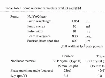
The all-solid-state (or “holosteric”) optical parametric oscillator has resulted from the recent development of diode-laser-pumped solid-state lasers and from recent advancements in new optically nonlinear materials. As a result, all-solid-state sources of widely tunable (ultraviolet - visible - near infrared) coherent radiation are now possible by using the radiation from diode-laser-pumped solid-state lasers, either directly or after frequency conversion, to pump optical parametric oscillators. Such devices can be made compact, efficient and reliable. The work described in this thesis explores the feasibility of obtaining widely tunable radiation from such devices, with particular reference to low threshold, high efficiency operation, so requiring only modest energies (1 mJ in ultraviolet) from the pump source. In particular, a frequency tripled or frequency quadruped Nd:YAG laser pumped by pulsed, GaAlAs diode laser bars has been used as the pump source, and lithium triborate has been used as the nonlinear medium in the optical parametric oscillator.
Two geometries of lithium triborate crystals have been investigated as the nonlinear medium. One was cut for a type II non-critical phase matching geometry, while the other was cut for a type I critical phase matching geometry. The oscillator cavities were designed for optimum focusing and mode matching aiming for operation with a low pump energy through the use of tightly focused pump radiation. The ultraviolet pump source was based on a Q-switched diode-laser-pumped Nd:YAG laser which generated pulses at 1.064 pm with energy 10 mJ and duration around 10 ns. These were then frequency up-converted to the UV at 355 nm or 266 nm, so as to be suitable for pumping the parametric oscillators. Generally, an overall conversion efficiency from 1.064 pm to 355 nm of >30% was obtained using the nonlinear materials potassium titanyl phosphate and lithium triborate for second harmonic generation and sum-frequency mixing respectively. For conversion to 266 nm, an overall efficiency of > 18 % was obtained using the nonlinear materials KTP and BBC for two step second harmonic generation.
a 1° walkoff angle, the minimum oscillation threshold was measured to be around 0.3 mJ. Generally, pump depletions of about 35 % were obtained, at around four times threshold. These devices could be angle tuned (through crystal internal angle 14°) from 457 to 666 nm (signal wave) and 1.6 pm to 768 nm (idler wave). (The whole of the range 420 nm to 2.3 pm could be covered with such a device given additional mirror sets). The all-solid-state type II geometry lithium triborate optical parametric oscillator was also pumped at 266 nm, when it was temperature tunable (20 - 200 °C) from 306 to 314 nm (signal wave) and 2.03 to 1.75 pm (idler wave). Pump depletions of 25 % were demonstrated with this device at pump energies of four times threshold.
Table of Contents
CHAPTER 1 Introduction 1
1.1 The concept of the "all-sohd-state optical parametric oscillator" 1 1.2 Brief historical review and contemporary developments 2
1.3 UV pumped optical parametric oscillator 6
1.4 Research programme 11
1.5 Outline of the thesis 11
References 13
CHAPTER 2 Theoretical background 16
2.1 The optical parametric interaction process 16
2.2 Phase matching theory and relevant parameters 17
2.2.1 Phase matching 17
2.2.2 Effective nonlinear coefficients 17
2.2.3 Double refraction and walkoff angle 23
2.2.4 Acceptance angle and temperature bandwidths 25
2.3 Parametric gain and pump threshold 28
2.4 Conversion efficiency 33
2.5 Frequency tuning 35
References 37
CHAPTER 3 Nonlinear optical material 39
3.1 Figures of merit of a material 39
3.2 An overview of nonlinear materials for use in the UV 47 3.3 Selection of the optical parametric oscillator gain medium 49
3.4 Lithium triborate (LBO) crystal 51
References 59
CHAPTER 4 Pump sources 61
4.1 Flashlamp pumped Nd: Y AG laser 62
4.2 Diode laser pumped Nd: Y AG laser 64
References 80
CHAPTER 5 Type II non-critical phase matched lithium triborate optical parametric oscillator pumped at 355 nm and
266 nm 82
5.1 Pump geometry 83
5.2 Type n non-critical phase matching geometry in LBO 84
5.3 Cavity 85
5.3.1 Cavity with plane-parallel geometry 86
5.3.2 Cavity with tightly focused pump 86
5.4 Oven and temperature controller 87
5.5 Performance of type II non-critical phase matched LBO optical
parametric oscillator pumped at 355 nm 88
5.5.1 Pump threshold 88
5.5.2 Conversion efficiency 90
5.5.3 Temperature tuning behaviour 93
5.5.4 Linewidth 96
5.5.5 Characteristics of output beam 96
5.6 Performance of type II non-critical phase matched LBO optical
parametric oscillator pumped at 266 nm 97
References 102
CHAPTER 6 Critically phase matched lithium triborate optical parametric oscillator pumped at 355 nm 104
6.1 Pump scheme 105
6.2 Type I critical phase matching geometry in LBO 105
6.3 Cavity 106
6.3.1 Confocal cavity with zero power mirrors 107
6.3.2 Operational performance 109
6.3.3 Explanation of the damage on the cavity mirrors 111 6.4 Performance of type I critically phase matched LBO optical
parametric oscillator pumped at 355 nm 112
6.4.1 Pump threshold 112
6.4.2 Conversion efficiency 114
6.4.4 Linewidth 117
6.4.5 Characteristics of output beam 118
6.5 Brief discussion of type II critically phase matched LBO optical
parametric oscillator pumped at 355 nm 118
References 121
CHAPTER 7 Conclusions and future work 122
7.1 Conclusions 122
7.2 Further development 123
7.3 Future direction 125
References 127
APPENDIX I
Conversion efficiency for second harmonic generation, third harmonic generation and relevant theoretical results APPENDIX II
Optical properties for various commercially available nonlinear optical materials
APPENDIX HI
Theoretical calculations of phase matching conditions relating to
potassium titanyl phosphate for second harmonic generation, lithium triborate for sum-frequency mixing
and optical parametric oscillation APPENDIX IV
CHAPTER 1
Introduction
1.1 The concept of the "all-sohd-state optical parametric oscillator" 1.2 Brief historical review and contemporary developments 1.3 UV pumped optical parametric oscillator
1.4 Research programme 1.5 Outhne of the thesis
References
This thesis describes the development and experimental demonstration of optical parametric oscillators (OPO) pumped by Q-switched sources, and based on noncritical phase matching (NCPM) and critical phase matching (CPM) geometries in lithium triborate (LiB^O^, LBO) in aU-solid-state schemes. The principal goal of this work was to investigate the feasibility of operation of low threshold compact OPO devices using only modest pump energies from diode pumped, Q-switched NdrYAG lasers, as well as investigating the newly developed nonhnear material hthium triborate as an OPO gain medium operating and tuning in the ultraviolet (UV), visible and near infrared (~IR) bands. Essential to the operation of such devices, was the optimization of frequency doubling, tripling and quadrupling schemes, in order to provide all-solid-state UV pump sources. Ah these aspects are discussed in this thesis.
1.1 The concept of the ”all-solid-state optical parametric oscillator"
Recently the meaning of "Holosteric" (i.e. all-solid-state) has become well known in the field of laser physics, but at the start of this thesis it is still worthwhile emphasising the concept again, which will be useful to our further discussion.
CHAPTER 1 Introduction
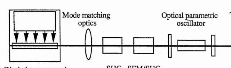
An example of such a device is the UV pumped, holosteric optical parametric oscillator shown as in figure (1-1)[2].
%
r r m
Mode matching optics
A
Optical parametric
oscillator Tunableoutput
Diode laser pumped solid state laser
V
[image:14.614.82.459.139.250.2]SHG SFM/SHG Frequency up conversion
Fig. 1-1 Configuration of an ah-solid-state optical parametric oschlator for the generation of radiation in the UV, visible and near infrared
regions of the spectrum.
Here an infrared solid-state laser (Nd:YAG, X = 1.064 pm) is pumped using diode lasers (GaAlAs semiconductor diode laser) and the radiation generated is then frequency shifted (by either frequency tripling or frequency quadrupling) into the ultraviolet so as to be suitable for pumping a solid-state optical parametric oscillator with an output tunable in the UV, visible and near infrared regions of the spectrum.
1.2 Brief historical review and contemporary developments
As continuously tunable coherent hght sources, optical parametric oscillators have already been of interest for a number of years now in many applications. The advantages of OPO's compared to normally tunable lasers, such as dye laser and solid- state vibronic lasers, which have long been regarded as convenient sources, is the very much greater tuning bandwidth.
such as compactness, longevity, high efficiency and better stability. Such devices have been demonstrated for sometime. The first publication in this area was perhaps from Byer et al, where a monolithic MgOiLiNbO] optical parametric oscillator pumped by the second harmonic of an amplified single mode diode pumped Nd:YAG laser was described[3]. The first demonstration of optical parametric oscillation tunable in the visible and the UV band with an all-solid-state scheme was carried out by our research group[2].
In reality, all-solid-state optical parametric oscillators have greatly benefited from the advances in two different technologies which are nonlinear optical materials and diode lasers. Those technologies have developed in parallel for more than 30 years together with the technique of optical parametric oscillation itself. However, studies of the holosteric or all-solid-state OPO in which these three technologies are combined began just a few years ago, and since then progress has been rapid. A comparison of the tuning ranges addressed by optical parametric oscillators compared with other tunable sources is shown in figure (1-2).
Early work with optical parametric oscillators showed some potentially troublesome problems. Firstly the nonlinear optical materials then available showed either too low a nonlinear coefficient or damage threshold[4][5][6]. Secondly difficulty was encountered in building a suitable pump source, particularly in the ultraviolet, mainly due to the lack of a suitable nonlinear optical material for frequency up conversion[7]. So, it is understandable why in the past operation of OPO's has been confined primarily to infrared spectral regions; and why there has previously been limited interest in the OPO for generation of tunable radiation in the near ultraviolet and visible spectral regions. After Franken's first experiment[8], and despite considerable effort over 20 years, only a handful of nonlinear materials were commonly available until the early
1980's.
CHAPTER 1 Introduction cr U
I
ai<
g
O C/3 b O 0 Z < e z1
V oTf u <s < -sfi. 4>< U n. aa wJ «V) +ff) H Uu UU
C5 ac/5 0 1 o < > + ' m
s
HI
<NI
mCN8
(N ON »T) m .§> 'O W)I
ÜÙ c ‘c <N (3Û ÜU On .Wvisible and near-infrared radiation, and may replace the more established nonlinear crystal such as LiNbOg. LÜO3, KB5, lithium formate and urea, as well as KDP and its isomophs in most frequency conversion applications. Based on those newly developed materials, optical parametric oscillator devices are now commercially available[10]. After the first demonstration of the OPO in 1965[11][12], it is only now that for the first time OPO devices have really found a place in the tunable coherent light source market.
The diode laser was invented in the early 1960’s[13], but the development of reliable commercial devices only occurred from the early 1980's onwards. In recent years, the semiconductor diode laser spectrum has been extended to cover most of the band from visible red to mid-IR (630 nm - 27 qm). Very recently a blue green band (490 nm) laser diode has been demonstrated using II-VI materials[14]. Unfortunately the output beam quality of diode lasers is generally poor. Output powers in most cases are not sufficient, particularly with regard to the peak power capability and energy capacity of the diode laser to supersede the well developed solid-state lasers, even looking into the long term future. As a result its applications are limited in many cases. However, as a highly efficient pump source GaAlAs diode lasers with a wavelength around 810 nm have been well developed[15]. For long-pulse (quasi-CW) operation GaAlAs lasers at 2.4 kW peak power, 200 jis pulse width, 100 pps repetition, and for CW monolithic GaAlAs diode laser arrays at 20 W output level, are already commercially available. The life-time for these lasers has been demonstrated to be more than 10^ pulse and 3 x 10^ hours respectively[16]. The maximum output power has been demonstrated to be as high as 120 W for CW devices using a diamond heat-sink to dissipate generated heat[17].
CHAPTER 1 Introduction
solid-state lasers have very quickly grown more popular. In the near future in low and even in the medium power devices, the diode lasers will replace the flashlamp as a highly efficient pump source.
It is interesting to note that the trivalent rare earth ions are natural candidates for resonant pumping due to their sharp absorption hnes. Some of these ions Nd^"^, Dy^+, Er^’^, Tm^'^’ and Yb^”** have strong absorption lines around the 800 nm region and the laser action is found in 1-3 jim band with relatively high conversion efficiency[18]. Based on those diode pumped solid-state lasers, and highly efficient frequency up shifting techniques, the all-solid-state optical parametric oscillator covering the frequency tuning range from 300 nm to 12 pm becomes practicable. Although, the use of diode pumped, Q-switched, frequency up converted Nd:YAG laser for OPO's operating in the visible generally results in some reduction in overall system efficiency, because of the additional frequency conversion processes, the high efficiency associated with every hnk still results in a high overall efficiency compared to the cases of normal ion lasers or excimer lasers used as the pump sources. Marshall et al have demonstrated an eye-safe laser based on all-solid-state OPO technology, and they have observed 2 % total wall-plug efficiency with adequate useful output at 1.61 and 1.54 pm[19].
The field of aU-solid-state OPO's is moving rapidly. The author believes that this review is reasonably topical at the time of writing, although clearly there will be advances in the field before completion of this thesis.
1.3 UY pumped optical parametric oscillator
The UV pumped optical parametric oscillator ( pump wavelength < 355 nm ) providing output wavelengths tunable in the UV, visible and near infrared was limited before 1984 due to a lack of nonlinear optical materials that can be phase matched in the UV, have a high nonlinear coefficient, and high optical damage threshold.
later, an ever higher conversion efficiency was demonstrated by Ebrahimzadeh et al[22] with a urea OPO pumped at 308 nm by an excimer laser. A 66% conversion efficiency were demonstrated over a narrow wavelength range 537-720 nm close to noncritical phase matching condition. Although crystalline urea has a very high single-shot optical damage threshold, it suffers from long term optical damage problems and was soon superseded by the new nonlinear optical crystal p-barium borate[23], which is comparatively easy to grow and has superior crystal properties.
UV pumped p-barium borate OPO's were reported by many authors from 1988 onwards. A representative result for a BBO OPO pumped at 355 nm is that of Byer et al[24]. They demonstrated a 140 mW average output power at the signal wavelength and 24 % total conversion efficiency. This device can continuously tuned from 412 nm to 2.55 p.m. A BBO OPO pumped at 266 nm, using a quadruped NdiYAG laser, was reported by Bosenberg et al[25]. Their OPO generated continuously tunable light over the range 330 nm to 1.37 |im. BBO OPO's pumped at 308 nm by excimer lasers have also been investigated by some authors. Ebrahimzadeh et al[26] have demonstrated tunable radiation over the entire spectral range from 354 nm to 2.37 pm and energy conversion efficiencies of great than 10 %. High pump depletions (70 % in a double pass pump geometry[27]) and external conversion efficiency (32 % with the use of dual crystal geometries[28]) have been reported in the last year. BBO has been identified by many experiments as a superior nonlinear material in the ultraviolet, but, due to BBO's larger Poynting vector walkoff angle and relatively small angular acceptance it is not suitable for operation at lower pump powers, where tightly focussing the pump laser is not helpful.
CHAPTER 1 Introduction
well as critical phase matching configurations has been demonstrated in this laboratory. In the former case, 40 % pump depletion and 30 % external efficiency has been achieved when a signal wavelength of 385 nm and idler wavelength of 1.54 jam is parametrically generated[31]. In the later scheme, tuning ranges of 355-497 nm in the ultraviolet/blue spectral region, and 809 nm - 2.34 jam in the near infrared have been obtained with a pump depletion of 28 %[32]. A type II NCPM LBO OPO pumped at 355 nm was first reported by Hanson et al[33]. They demonstrated a temperature tunable OPO around 470-487 nm blue band with 12,5 % conversion efficiency at room temperature. A type I CPM LBO OPO pumped at 355 nm was first demonstrated by Chen et al[34] with tuning from 435 nm to 1.92 jam and an overall conversion efficiency 14 %.
Table (1-1) possibly lists aU the published experimental investigation results of UV pumped optical parametric oscillators.
However, these particular noncritical and critical geometries had not been pumped with an all-solid-state pump source before the present studies. Successfully operating such devices with modest energy from recently developed diode pumped solid-state lasers requires two basic pre-conditions to be fulfilled: firstly high conversion efficiency in frequency up conversion to the UV; and secondly, low threshold for optical parametric oscillation.
Table 1-1 Performance of some UV pumped optical parametric oscillator Pump Material
wavelength (pm) Tuning Range (pm) Pump
Threshold Characteristic st Ref.
0.355 KDP
0.35 KDP
0.266 ADP
(OPG)tt 0.266 ADP 0.96-1,16 0.53 1.06 0.42-0.73 0.458-0.638
0.347 LiI03(17mm)
Single mode Cut at 45® 0.415-2.1 l-4MW/cm2
0.355 0.355 0.355 0.355 0.308 0.266 0.308 Injection seeded 0.308 0.355
Urea(l 2.7 mm) 90® Phase match
Urea(23mm) 90® Phase match
0.5-0.51 1.17-1.22
0.498-0.640 0.79-1.23 BB0(11.5mm) 0.45-1.68 Cut at 30®’ Type I
BB0(12mm) Cut at 35® and 45®
Type I BB0(7mm) Cut at 36®, Type I
0.412-2.55
BBO(20.5mm) 0.33-1.37 Cut at 39.1®^ Type I
4.5mJ, 7ns 0.388MW/cm2 1.4mJ, 7ns 8ns 130MW/cm2 2-5mJ 15-36MW/cm2
0.422-0.477 2mJ, 12ns
Urea(15mm) 90® phase match
Urea
BBO
(11.5+9.9mm) Cut at 30.2® and
29.3® 0.537-0.720 0.537-0.72 4.5mJ 23MW/cm2 4-5mJ 16-20MW/cm2 0.42-2.3 1.7mJ 27MW/cm2 [35] [36]
100kW(Peak) [37] 25%, 2ns
Line width 5Â
Limited by optical [38] damage
lOkW (peak) [39] 8%, 5ns
91kW (peak) [20] 6mw (Average)
20%
23% [21]
Line width 1.2Â
1.4mJ [40]
9.4%
4.7mJ [24]
140mW (Average) 24%
0.7mJ [41]
10%
Limited by optical [25] damage
3.8mJ(Signal) [42] 37%
llm J
66%
[
22]32% [28]
CHAPTER 1 Introduction
0.308 Injection
seeded
BB0(12mm)
Cut at 32®^ Type I 0.354-2.37 4.5mJ-10mJ0.125-0.28J/cm2 12.5-28MW/cm2
2mJ
10% [26]
0.355 BBO(17+10mm)
Cut at 37®, Type II 0.48-0.630.81-1.36 38MW/cm22.4mJ Line width 0.5-3Â12% [43]
0.355 LBO( 16.4mm)
Cut at 45.4®, Type I 0.54-1.03 2.4mJ12MW/cm2 14% at 0.674 [34] 0.355
Injection seeded
LB0(16mm)
Type II NCPM 0.480-0.487 Line width 0.2Â12% [33]
0.355 BBO(lOmm)
Cut at 29.7®,Type I 0.415-2.411 13mJlOMW/cmZ 70%*41% [27]
0.308 LB0(16mm)
Type II, NCPM 0.385 0.3J/cm217ns 40%* at 0.385 [31]
0.266 LBO(16mm)
Type n, NCPM 1.74-0.314-0.311 0.5mJ, 10ns 25%*7% [44]
0.355 LB0(16mm)
All solid Type II, NCPM state scheme
0.481-0.457
1.355-1.590 0.42mJ0.18J/cm2 15MW/cm2
50%*
27% [1]
0.308 LB0(15mm)
Cut at 40®, Type I 0.355-0.4970.809-2.34 0.45J/cm217ns 28%* [32] 0.355
All solid state scheme
LB0(15mm)
Cut at 40®, Type I 0.457-0.6660.768-1.590 0.3mJ, 10ns 35%* [45]
0.355 LB0(16mm)
Aff solid Type II, NCPM state scheme
0.481
1.355 0.6J/cm2 0.19mJ, 10ns 60 MW/cm2 50%* [2] 0.266 All solid state scheme LB0(16mm)
Type n, NCPM 0.314-0.3061.74-2.03 0.48mJ, 10ns 25%* [2]
t % figures are conversion efficiency; starred values are internal, others are external, t t Optical parametric generation only and not oscillation.
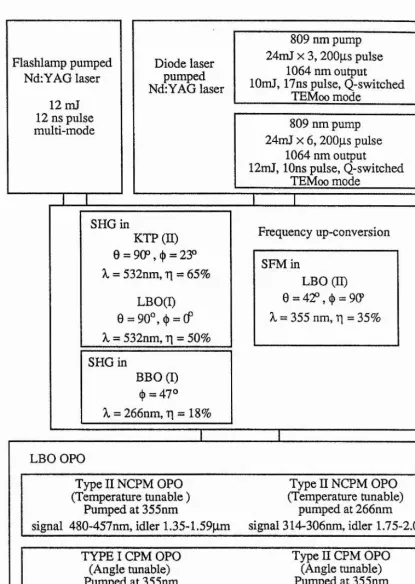
1.4 Research programme
The programme of work is outlined in figure (1-4), which is divided into three parts. One part is to construct a diode laser pumped, Q-switched Nd: YAG laser, one is to set up a highly efficient UV pump source using frequency up-conversion techniques, and the last development of OPO itself for tuning in the UV, visible and near infrared bands.
In order to allow the development of frequency up conversion techniques and optical parametric oscillator to proceed from the start of the project, the initial nonlinear optical experiments were carried out using a flashlamp pumped Nd:YAG laser (restricted to low pulse energy operation). The diode laser pumped solid-state laser was developed simultaneously, and subsequently combined with the nonlinear optical devices in the latter stages of the project
1.5 Thesis outline
CHAPTER 1 Introduction
Flashlamp pumped Nd:YAG laser
12 mJ 12 ns pulse multi-mode
Diode laser pumped Nd:YAG laser
809 nm pump 24mJ X 3, 200ps pulse
1064 nm output
lOmJ, 17ns pulse, Q-switched TEMcx) mode
809 nm pump 24mJ X 6, 200jis pulse
1064 nm output
12mJ, 10ns pulse, Q-switched TEMoo mode
SHG in
KTP (B) 0 = 9OP,«|) = 23°
X = 532nm, T[ — 65%
LBO(I)
e = 9o°,(|) = cr
X = 532nm, r\ = 50% SHG inBBO (I) (|) = 47°
X = 266nm, Tj = 18%
Frequency up-conversion
SFM in
LBO (H)
355 nm, r\ = 35%
I
LBO OPO
Type n NCPM OPO (Temperature tunable )
Pumped at 355nm
signal 480-457nm, idler 1.35-L59pm
Type n NCPM OPO (Temperature tunable)
pumped at 266nm
signal 314“306nm, idler 1.75-2.03|im
TYPE I CPM OPO Type H CPM OPO
(Angle tunable) (Angle tunable)
Pumped at 355nm Pumped at 355nm
signal 666nm-457nm, Signal 535nm-501nm
idler 768nm-1.59pm idler 1.052nm-1.215pm
Fig. 1-3 Frame-work of the experiment organisation and some main results.
[image:24.614.79.495.57.641.2]References
(1) Y. Cui, M. H. Dunn, C. J. Norrie, W. Sibbett, B. D. Sinclair, Y. Tang
and J. A. C. Terry Opt. Lett. 17(9), 646, 1992
(2) Y. Cui, M. H. Dunn, C. J. Norrie, W. Sibbett, B. D. Sinclair, Y. Tang and J. A. C. Terry
in Conference on Lasers and Electro-Optics (Anaheim, California, USA) OSA Technical Digest Series, 12, Paper CTuRl, 1992
(3) W. J. Kozlovsky, E. K. Gustafson, R. C. Eckardt, and R. L. Byer Opt. Lett. 13(12), 1102, 1988
(4) R. L. Byer
in "Quantum Electronics : a traties", edited by H. Rabin and C. L. Tang, (Acadamic, NewYork) Vol. 1, Pat B, 587-702,1975
(5) S. E. Harris
Proc. IEEE 57(12), 2096, 1969 (6) R. G. Smith
in "Lasers", edited by A. K. Levine and A. J. DeMaria, (Dekker, New York), 189, 1976
(7) R. Pixton
Laser Focus, 14(7), 66, 1978 (8) R. A. Franken et al
Phys. Rev. Lett. 7(4), 118, 1961 (9) T. H. Higgins
Laser Focus World 28(1), 125, 1992
(10) W. Bosenberg, D. Guyer, D. D. Lowenthal and S. E. Moody Laser Focus World 28(5), 165, 1992
(11) C. C. Wang and G. W. Racette Appl. Phys. Lett. 6(8), 169, 1965 (12) J. A. Giordmaine and R. C. Miler
Phys. Rev. Lett. 14(24), 973, 1965
(13) R. N. Hall, G. E. Fenner, J. D. Kingsleg, T. J. Soltys, and R. O. Carlson Phys Rev. Lett. 9(9), 366, 1962
(14) M. A, Haase, J. Qiu, J. M. Depuydt, and H. Cheng Appl. Phys. Lett. 59(11), 1272, 1991
(15) W. Streifer, D. R. Scifres, G. L. Hamagel, D. F. Welch, J. Berger and M. Sakamoto
CHAPTER 1 References
(16) D. W. Hughes and J. R. M. Barr,
J. Phys. D: Appl. Phys. 25(4), 563, 1992 (17) M. Sakamoto, J. G. Endriz and D. R. Scifres
lEE Electron. Lett. 28(2), 197, 1992 (18) T. Y. Fan and R. L. Byer
IEEE J. Quantum Electro. 24(6), 895,1988 (19) L. R. Marshall, A. Kaz, R. L. Burnham
in Conference on Lasers and Electro-Op tics (Anaheim, California, USA) OSA Technical Digest Series, 12, Paper CWQ2, 1992
(20) W. R. Donaldson and C. L. Tang Appl. Phys. Lett. 44(1), 25, 1984 (21) M. J. Rosker and C. L. Tang
J. Opt. Soc. Am. B2(5), 691, 1985
(22) A. J. Henderson, M, Ebrahimzadeh, and M.H. Dunn J. Opt. Soc. Am. B7(8), 1402, 1990
(23) Chen C. T., Wu B. C., Jiang A. D., and You G. M. Scientia Sinica(b), 28, 235, 1985
(24) Y. X. Fan, R. C. Eckardt and R. L. Byer, J. Molting and R. Wallenstein Appl. Phys. Lett. 53(21), 2014, 1988
(25) W. R. Bosenberg, K. L. Cheng and C. L. Tang Appl. Phys. Lett. 54(1), 13, 1989
(26) M. Ebrahimzadeh, A. J. Henderson and M.H. Dunn IEEE J. Quantum Electron. 26(7), 1241,1990
(27) Y. P. Wang et al
Appl. Phys. Lett. 58(14), 1461, 1991
(28) W. R. Bosenberg, W. S. Pelouch and C. L. Tang Appl. Phys. Lett. 55(19) 1952, 1989
(29) C. T. Chen, Y. C. Wu, A. D. Jiang, B. C. Wu, G. M. You, R. K. Li, and S. J. Lin
J. Opt. Soc. Am. B6(4), 616, 1989
(30) FC CASTECH Inc. Trade Literature on LBO June 1991
(31) G. Robertson, A. Henderson and M. H. Dunn Opt. Lett. 16(20), 1584, 1991
(32) G. Robertson, A. Henderson and M. H, Dunn Appl. Phys. Lett. 60(3), 271, 1992
(33) F. Hanson and D. Dick Opt. Lett. 16(4), 205, 1991
(34) Z. Y. Xu, D. Q. Deng, Y. P. Wang, B. C. Wu and C. T. Chen
in Conference on Lasers and Electro-Optics (Anaheim, California, USA) CLEG 1990, OSA Technical Digest Series, Paper C \ ^ 6 ,1990
(35) Khoklov,
JETPLett 3,241,1966 (36) S. A. Akhmanov et al
Modem Optics, 17, Polytechnic Press. New York, p 343 (37) J. M. Yarborough and G. A. Massey
Appl. Phys. Lett. 18(10), 438, 1971 (38) R. W. Wallace
IEEE J. Quantum Electron. 7(6), 307,1971 (39) G. Nath and G. PauH
Appl. Phys. Lett. 22(2), 75, 1973
(40) K. L. Cheng, W. R. Rosenberg and C. L. Tang Appl. Phys. Lett. 53(3), 175, 1988
(41) H. Komine
Opt. Lett. 13(8), 643, 1988
(42) M. Ebrahimzadeh, M. H. Dunn and F. Akerboom Opt. Lett. 14(11), 560, 1989
(43) W. R. Rosenberg and C. L. Tang Appl. Phys. Lett. 56(19), 1819, 1990
(44) Y. Tang, Y. Cui and M. H. Dunn Opt. Lett. 17(3), 192, 1992
(45) Y. Cui, D. E. Withers, C. F. Rae, C. J. Norrie, Y. Tang, B. D. Sinclair, W. Sibbett, and M. H. Dunn
CHAPTER 2 Theoretical background
CHAPTER 2
Theoretical background
2.1 The optical parametric interaction process 2.2 Phase matching theory and relevant parameters
2.2.1 Phase matching
2.2.2 Effective nonlinear coefficients 2.2.3 Double refraction and walkoff angle
2.2.4 Acceptance angle, frequency and temperature bandwidths 2.3 Parametric gain and pump threshold
2.4 Conversion efficiency 2.5 Frequency tuning
References
The nonlinear interaction among three electromagnetic fields has been described by Armstrong et al. in 1962[1] and later by many other authors[2]-[5]. Therefore, the theoretical analysis of three wave interactions in nonlinear optical materials is not discussed in detail in this thesis. However, those aspects of linear and nonlinear optical theory required for the analysis of the nonlinear materials used are summarised here. MKS units were used throughout.
2.1 The optical parametric interaction process
It is well known that when a strong electromagnetic wave propagates through a nonlinear medium, a nonlinear polarisation field is induced. This process lead to many different effects in the optical spectral band, such as second harmonic generation, sum- frequency mixing, and parametric interactions in the case of second order nonlinear effects. The parametric interaction of particular interest here is the following. In this process a strong, high frequency pump wave (frequency cOp and wave vector Kp) is incident on a nonlinear crystal, and interacts via the nonlinear response of the medium with two lower-frequency electromagnetic waves at 0)g and coi (C0s>C0i), which are referred to as the signal and idler waves respectively, where
COp = œs + coi 2-1 and
Kp = Kg + Ki , 2-2
Kg and Ki being the wave vectors of signal and idler respectively. As a result of this interaction, there is a power flow from the strong pump wave to the weak signal and idler fields. If the nonlinear medium is enclosed within a resonator which is resonant at either the signal or idler wavelengths separately (single resonant) or at both simultaneously (doubly resonant), oscillation can take place. Such a device is known as an optical parametric oscillator, and has been extensively studied both theoretically and experimentally[6] - [ 11 ]. It is important that the momentum conservation (i.e. the phase matching) condition given by (2-2) be satisfied for effective operation of the oscillator.
2.2 Phase matching theory and relevant parameters
2.2.1 Phase matching
Deviation from the phase matching condition is measured by the phase mismatching parameter AK, defined by
AK = Kp-Kg-Ki 2-3
(The condition AK = 0, corresponds to phase matching) The parametric gain is critically dependent on the magnitude of this parameter. As AK increases, a reduction in gain occurs. Using the relation K = kKo = (co/c)nKo, (2-2) can be written as
np'COp = ng’COg + ni’COi 2-4
Where np, ng and n{ are the refractive indices at pump, signal and idler wavelengths respectively. From (2-4), we see that phase matching depends on the values of the refractive indices of the material as a function of wavelength.
CHAPTER 2 Theoretical background
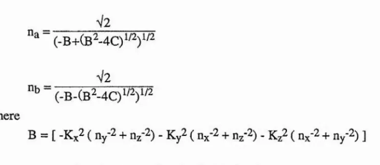
indices[2]-[4]. Using na and np to represent the refractive indices of the two eigenvectors, and with na < ny, from the Fresnel equation[12] we get
V2
V2 ny
2-5
2-6
where
B = [ -Kx2 ( ny-2 + nf2) _ Ky2 ( nx'2 + nz'2). + n/^) ] 2-7
C = [ K%2 ny'2n2‘2 + Ky2 nx'^ng-^ + nx’^ny-2 ] , 2-8
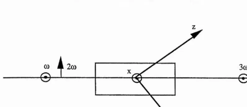
where n%, ny and n% are the refractive indices of crystal principal axes, and Kx, Ky and Kz are the cosine vectors of K measured relative to the principal optical axes. If we use "0" to denote the polar angle between K and the principal axis z, and (j) to denote the azimuthal angle from the x axis in the principal plane defined by the x and y axes, then
Kx = sin0cos(|)
Ky = sin0sin(|)
Kz = COS0
2-9
Fig. 2-1 Definitions of the angles 0 and ^ describing the propagation direction of K relative to the mutually orthogonal x, y, z axes.
[image:30.614.83.455.118.280.2]In a normal dispersive and anisotropic medium there exist three possible phase matching process, which are given by
np,a* ” ^s,b * ^ ^i,b * COi 2-10
i^p,a* (*)p — %,a * 0)s +ni^b • COj 2-11
*^p,a* (bp = ng,b * + nj^a • COj 2-12
Usually these conditions are called type I, type II, and type III phase matching conditions respectively.
In a uniaxial crystal the indices are such that Ux = ny = Uq and n^ = üq. If ng > n^, it is called a negative uniaxial crystal, and if ng < ng, it is called a positive uniaxial crystal. For both of them one eigenvector of a given wave vector K must be an ordinary wave, where the other one is usually an extraordinary wave. The eigen-refractive-indices for both negative or positive uniaxial crystals are listed in table I.
Using table I and the expressions (2-10), (2-11) and (2-12), it can be seen that in a negative crystal, phase matching can in principle be achieved with an extraordinary pump and either one or both of the signal and idler being ordinary wave, whereas in a positive uniaxial crystal the pump must be an ordinary wave, and either the signal or the idler or both of them must be extraordinary.
CHAPTER 2 Theoritical background
Table I Eigen refractive indices of uniaxial crystal
Crystal % nb
Negative uniaxial crystal
/ sin^G cos^G ..1/2
ne^ ^ no^ no
Positive uniaxial crystal
no , sin^G cos^G n@2 ng2 y l/2
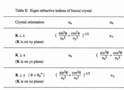
Table II Eigen refractive indices of biaxial crystal
Crystal orientation na nb
K_Lz
(K is on xy plane)
/ sin2()) cos^(|> y 1/2
nz
K l x
(K is on yz plane)
nx / sin^G cos^G
^
nz2 ' ny2 y l/2KJLy ( e < 8o*) (K is on xz plane)
. sin^G cos^G 4/2
^ n,2 + n,2 ) ny
K_Ly ( 8 > 8o*) (K is on xz plane)
ny
(
^ sin^G cos^Gnz2 ' nx2 \-l/2* The definition of 8o, please see text.
[image:32.616.68.474.107.278.2] [image:32.616.61.476.372.671.2]2.2.2 Effective nonlinear coefficient
For a given phase matching condition the effective nonlinear coefficient is determined by crystal symmetry and the direction of wave propagation within the crystal. The phase matching direction in a crystal should be chosen in such a way as to maximise the value of effective nonlinear coefficient dgff.
Boyd and Kleinman[12] have defined the effective nonlinear coefficient dgff to cover all the cases of three wave interaction processes. In the parametric interaction process this is given by
dgff = d(2o))i^ 2-13
(i = 1,2,3; ^ = 1 , 2 , --- 6 )
where, d(2co) is the second order nonlinear polarization tensor of the material; and are the unit vectors of the polarization direction of the electric fields at frequencies coi, (Og and cOp respectively in the crystal; is the ith component of the
is the symmetrized column vector which has the components,
+ U<‘>kUWj)(l- J 8jk) ( j, k = 1,2, 3 ) 2-14
% = %(jk) is the condensed notation. The relation between the values of j, k and ç are given by
1, 2, 3, 4, 5, 6,
jk: 11, 22, 33, 23,32, 13,31, 12,21,
ôjk is a delta function.
CHAPTER 2 Theoretical background
Now the cosine vectors of the electric field of a monochromatic plane wave propagating in the crystal can be written as
U<o„,i : cos(a(o^,i), cos(pai„,i). cos(Yo,„,
0 2-16where m could be i, s, or p, referring to the frequency coi, cOg» cOp, and the subscript i could be a or b, referring to the two possible values of the eigen-refractive-index in the propagation direction K. The column vector for type I geometry is
cos(acûi,b) cos(ao)g,b) cos(po)bb) cos(pcOs,b) cos(Ym.,b) cos(Ycos,b)
cos(TfOi, b) cos(P(Og,b) + cos(Tcos,b) cosCPmyb) 2-17
cos(To)i, h) cos(ao)3,b) + cos(7(0g,b) cos(ag).,b) cos(acübb) cos(p(Og,b) + cos(ao3s,b) cos(p(o-,b)
For type II phase matching, the coi and cOg waves are orthogonally polarized and the column vector is
cos(ao)j,a) cos(ao)g,b) cos(po3i,a) cos(pcû3,b) cos(7(o.,a) cos(7(0g,b)
cos(Pcoi. a) cos(7mg,b) + cos(P@g,b) cos(Y(o.,a)
cos(aQj.^ a) cos(Y(Og,b) + cosCa^,^ y) cos(Y®ya)
cos(acoya) cos(pcû3,y) cos(a(Og,y) cos(p(a-,a)
2-18
For both type I and type II
u ‘P> = cos(Ocop,a) cos(P(Op,a) cos(Y(Op,a) 2-19
2.2.3 Double refraction and walkoff angle
The optimum phase matching directions for an optical parametric processes can be determined from the calculations of the phase matching angle and the effective nonlinear coefficient. However, double refraction will prevent full use of the nonlinear optical properties of a crystal, because for a plane wave the direction of the wave vector and the Poynting vector do not generally coincide inside the crystal. In this case the energy of the generated wave walks off at a finite angle from that of the incident wave, limiting the effective volume over which efficient interaction of the three waves may take place.
In an anisotropic medium, for an extraordinary wave there is an angle of deviation p, called the double refraction angle, between the Poynting vector S and the wave propagation direction K, and also between the electric field E and the electric displacement vector D. The value of p depends on the birefringence of the materials, the frequencies and the propagation directions of the interaction waves. The relation between E, D, K, and S, is shown in figure (2-2), where, all the four vectors are in the same plane and are orthogonal to the magnetic field H.
E
[image:35.615.178.387.396.546.2]H
Fig. 2-2 Relation between the wave propagation direction K and the Poynting vector S, and between the electric field E and electric displacement vector D in an anisotropic medium.
It is clear from figure (2-2), the double refractive angle p is generally
tan p =
CHAPTER 2 Theoretical background
where Eq, Dq and Kg are the unit vectors of E, D, and K respectively. Starting from Maxwell's equation, and after a few steps of derivation, we can get[14]
where n is the refractive index in the direction Kg given by (2-5) and (2-6), and n^, ny and nz are the refractive indices of the principal axes. This allows the calculation of the double refraction angle p between the energy flow and the direction of the wave propagation Kg (Kx, Ky, Kz ).
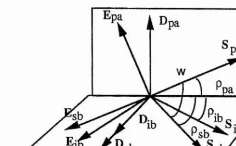
In the parametric interaction processes, the maximum angle w overall between the Poynting vector associated with the three waves is called the walkoff angle. By the calculation (2-21) we know that, if two eigenwaves at frequencies coi and C02 have same polarisation direction, then the high frequency eigenwave has a bigger double refraction angle p than the low frequency eigenwave. Therefore, in a uniaxial crystal, or in a biaxial crystal in which the pump wave propagates with the restricted conditions given by section (2.2.1) i.e. the pump wave polarisation is orthogonal to any one of the principal axes, one eigenwave vector must be ordinary and the walkoff angle will be the double refraction angle of the extraordinary eigenwave with the highest frequency. In a biaxial crystal, if the pump wave vector is not orthogonal to any of the principal axes, then all three eigenwave vectors will be extraordinary, and there will be three double refraction angles. The Poynting vectors associated with signal and idler waves lie in the plane containing the wavevectors K (all collinear), and the pump Poynting vector lies in a plane orthogonal to this plane but also containing K (see figure (2.3)). The walkoff angle w is defined as biggest angle difference between the energy flow’s unit vectors, they are lie in two orthogonal planes which intersect in the propagation's unit vector Kg. For an example figure (2-3) shows the relations between double refraction angles under the type I phase matching conditions. In this case the walkoff angle w is given by
cos w = cosppa • cospsb 2-22
The detailed behaviour of wave propagation in a nonlinear biaxial crystal has been thoroughly discussed in reference [15].
Epa
1 ^pa
^pa w
Ppa K ib Dsb
Fig. 2-3 The double refractive walkoff angle in the biaxial crystal (type I geometry) when the pump wave vector is not orthogonal to any of the principal axes.
2.2.4 Acceptance angle and temperature bandwidths
An important parameter in relation to the application of nonlinear optical materials is the acceptance bandwidth, which gives the allowable variation of the pump wavelengths, the pump beam propagation directions, and the temperature of the nonlinear medium.
1.0
0.8
0.6
•o
*o
0.4
0.2
0.5 1.5 2.0
6 (tt)
[image:37.620.124.368.73.224.2] [image:37.620.133.383.429.651.2]CHAPTER 2 Theoretical background
It is weU known that in the three wave parametric interaction processes (in the plane wave approximation) the small signal parametric gain is directly proportional to the function sinc^(^AkL), which shown in figure (2-4), In practice there are two definitions of the acceptance bandwidth. One is based on the maximum allowable wave vector mismatch being Ak = ± Tt/L[16][17], at which the conversion efficiency drops to approximately 0.4 (sinc^(^AkL) = 0.4) that of the peak conversion efficiency. The other definition is based on the maximum allowable wave vector mismatch being Ak = ± 2ti:/L, at which the conversion efficiency drops to zero. We prefer to use the second
definition throughout our analysis, and the calculation of the angular and temperature acceptance bandwidths are based on this basic definition. (The spectral acceptance bandwidth is not discussed in this thesis.) Assuming a is the most significant parameter determining Akin a specific case, and that the optimum phase matching is at a = cxo, then expanding Ak in a Taylor series at a = oco we obtain.
Ai All dAk, „ Id^Ak, , 2%
- Akl(x=ao + ^a=cco 5a + 2 ^^2 *a=ao - l
The parameter a could be the phase matching angle 0 or (j), or the phase matching temperature T. Normally expansion to second order in the Taylor series gives sufficient resolution for most applications. Therefore, the remaining problem is how we solve this quadratic equation. It is necessary to mention that acceptance bandwidths are calculated individually assuming optimum values of the other parameters.
Angular acceptance
The angular acceptance is defined as the planar angle over which the magnitude of the wave vector mismatch for the parametric generation process is no greater than lizfL.
Since two angles are needed to specify the direction of propagation with respect to the crystaUographic axes, two acceptance angle wiU be defined. For sake of simplicity, the wave vector mismatch will be expanded as a function of one angle at a time. In other words we consider 50 and 5(|) individually .
As an example, in order to define an acceptance angle in the 0 direction, a Taylor Series may be written as
Ak = Akl9=e„ + ^ 19=80 50 4 ^ W o (50)' = ± r 2-24
It is easy to see that the first term of this expansion is zero when the angle 9 is equal
to the optimum phase matching angle 0o, and the solution is then
i = 1, 2 ( at 0 = 0o) 50 = min ( 00i, Ô02)
Generally in the non-critical phase matching case, the first order term is negligible, because the phase matching angle is at either zero or ninety degrees. Hence the
acceptance angle can be written as
50 = 2 {(^ )/( (at 0 = 0o) 2-26
In the critical phase matching situation the first order term is normally much bigger than
the second order term, which can therefore be neglected. Much of the data given in the literature, particularly for critically phase matched SHG, is based on this approximation. In this case the acceptance angle is given by
5 e = ( ^ ) / ( ^ ) (at9 = 0o) 2-27
^ d0
Now we can by using the definitions of Ak and 0 and taking the derivatives of the functions B (2-7) and C (2-8) with respect to 0 given in section (2.2.1), now we can solve fo r^ ^ , and hence obtain solutions for 60.
d0
Temperature acceptance
Different nonlinear optical materials possess different thermal sensitivities, measured by the parameter ^ (called the temperature dependence of refractive index). For a temperature change AT from the optimum phase matching temperature Tq(T = Tq
CHAPTER 2 Theoretical background
Ak = ^ t=To 5T 4 't=To (5-^2 + 2-30
The temperature acceptance band width is defined as that change ôT leading to a value for Ak of ±2n/L. So that, from (2-30) we obtain
i = l , 2 (atT = To) ÔT =min(ÔTi,ÔT2)
The first-order approximation is
8T = ( Ç ) / @
In most cases ( ^ ) is nearly a constant and is independent of the pump wavelength, so that the above may be simplified to
Therefore, 5T can be found readily, provided that the ( ^ ) ’s are known.
Recently as the result of precise measurement of refractive indices of the new nonlinear materials, accurate Sellmeier equations have been deduced for them, and this information has now been widely published in the literature. It is now possible to calculate refractive indices to 1 part in 10*^[18]. Such information is required to evaluate the above expressions in specific situations. Detailed information and calculations for the materials of interest here are given in Appendices H and HE.
2.3 Parametric gain and pump threshold
We now consider parametric gain and pump powers necessary to reach oscillation threshold. Generally, obtaining low thresholds enable high conversion efficiencies to be reached.
In a singly resonant optical parametric oscillator, when a signal frequency at cOg is incident on the parametric gain medium, the single pass power gain is[l 1]
where
— 2c0iC0sdeff^Ip / aingUpEgC^ , 2-34
g2 = r 2 - ( ^ ) 2 . 2-35
Ip is the pump power intensity, Eq is the permittivity of free space, and c is the speed of
light in vacuum. For the small gain and perfect phase matching (AK = 0) case, the gain is thus sinh2(TL), and can be approximated as F^L^. As in a laser oscillator, threshold is reached when the parametric gain equals the loss, namely
r2L2 = 6g , 2-36
where ôg is the round-trip power loss of the signal wave. The pump power required to reach threshold is then
| ^ = 7uKoL2 , 2-37
Where Kqis defined as
TtEoningnpC^
CHAPTER 2 Theoretical background
not require tight focusing, in this case it is appropriate to use the plane wave approximation; if the available pump energy or power is not adequate, and optical parametric oscillation requires resort to tight focusing of the pump wave to reach the
pump threshold, then we use the Boyd and Kleinman theory. However, here the
limiting condition is crystal damage.
Boyd and Kleinman (1968)[12] have shown that the pump power threshold of second harmonic generation, sum-frequency mixing and optical parametric oscillation can be accurately described as a function of two parameters. One is the focusing parameter which is defined as the radio of the crystal length L to the confocal beam parameter b in the crystal, namely
Ç = ç 2-39
For Gaussian beam profiles the confocal parameter is given in terms of the beam waist Wo as follows
b = 2zo = kwo^ = Wq^ 2-40
K
The other parameter is the walkoff parameter B. In the optical parametric oscillator, this is defined by
B = § (L k )'/2 (^ )'" 2-41
where
tto “ 2 tt{) 2-42
and p is defined as the double refraction walkoff angle. For a given pump beam waist Wq, this walkoff limits the effective nonlinear interaction length in the crystal.
The original Boyd and Kleinman theory is valid in situations involving: CW pumping, doubly resonant oscillation of signal and idler wavelengths, and operation near degeneracy. Another assumption in the theory was that pump, signal and idler beam shared the same confocal parameter, and the consequences of them having different confocal parameters was not investigated. Following Boyd and Kleinman,
Fischer et al (1977)[19] first theoretically derived the threshold conditions for singly resonant OPO's with tightly focused pumps. However in their derivations the other assumptions are exactly the same as the Boyd and Kleinman's, including the condition of pump and signal sharing the same confocal parameter. In 1982, Guha, Wu and Falk theoretically extended the analysis to express the consequences of unequal confocal parameters[20]. Their conclusion was that lower thresholds can be generally achieved with unequal confocal parameters. They developed Boyd and Kleinman's theory, and derived singly resonant and doubly resonant OPO threshold formulae with unequal confocal parameters. Their results can be used to describe steady-state operation of pulsed, as well as CW optical parametric oscillators.
Consider an interaction under conditions of type I phase matching, where the pump is an extraordinary ray and signal and idler are ordinary rays then the reciprocal pump threshold can be written as
^ = KLh(Ç,B) 2-43
where
K = KoLkps , (W-i) 2-44
and h(4,B) is a function containing all of the dependence of the generated signal upon
the optimisable parameters[ 12] [20]. The h(^,B) function can be numerically calculated using a computer. In the general case, Guha's results shows that h(%,B) is maximised with unequal confocal parameters and that for certain values of and Çg, h(^,B) can be increased appreciably over its value for = %g. For example if ^p = 0.1, h(%,B) is increased by nearly a factor of two if the signal focusing parameter is increased from 0.1 to 0.5.
A theoretical derivation of the OPO threshold conditions for a type II phase matching geometry with a tightly focused pump has not appeared in the literature. However, a few papers have discussed type II second harmonic generation using Boyd
and Kleinman's theory[21][22]. Deriving the optimum threshold condition for a type II
phase matching geometry is more complicated than the type I situation. Since now in the general case two double refraction angles result. Fortunately in most OPO cases, the
CHAPTER 2 Theoretical background
B=0
K=1.35
1.00.5
0.05 -C
0.01 0.005
0.05 0.1 0.5 1.0 5.0 10.0
8=4.25
* 10'
K=1.65
20
10
7
4
2
1.0 0.5 Çpj=0.1 ^,,=0.052
^p,=0.01
0.01 0.05 0.1 0.5 1.0 5.0 10.0
Fig. 2-5 Theoretical calculation results of the optimized hm curve as a
function of signal focussing parameter under the different conditions of k = kp/kg and ^p.
principal axis, so that one or other of the signal/idler waves is an ordinary wave. Further in the non-critical phase matching geometry, the Poynting vector walkoff is eliminated (B=0). In this case the type I and type H geometries have the same optimised universal hm curve. Following Guha, Wu and Falk, we have predicted the optimum
hm curves suitable for our situations (see figure (2-5)), where k = kp/kg = 1.35, B = 0, for noncritical phase matching geometry, and k - kp/kg = 1.65, B= 4.25 for type I (e ^ o + o) critical phase matching geometry. These curves can be used to calculate the
steady state pump threshold, the optimum crystal length, the optimum pump beam spot size, and the optimum signal wave spot size in the OPO cavity, the latter determining the optimum radius of curvature of the OPO cavity mirrors. These aspects we wül fully discuss in the following chapters.
2,4 Conversion efficiency
The power conversion efficiency in an optical parametric oscillator can be considered in a similar way to the analysis of pump threshold, namely for either uniform-plane waves or Gaussian beams. These also have been discussed by many
authors[10][ll][23]-[27]. For simplicity, some conclusions which are useful to illustrate our experimental results are summarised below.
Let Ip be the incident pump intensity, % be the oscillation threshold intensity. Ip' be the intensity of pump beam transmitted through the oscillator, and Ig and li be the
intensities of the signal and idler beams respectively. For the singly resonant optical parametric oscillator, we have
Ig + Ij =5 Ip - Ip 2-46
The internal conversion efficiency, or pump depletion, defined as the fraction of the
pump power/intensity going into the signal and idler fields, is given by
n i „ t = ^ = l - ÿ . 2-47
CHAPTER 2 Theoretical background
under steady-state conditions and for the plane-wave, the internal conversion efficiency is given by
n i n t = [ l - ( ÿ ^ ] s i n 2 ( P L ) , 2-48
'2|
where p is defined by
sin2(PL) P,h sin2(AlcL/2) (PL)2 Pp (AkL/2)2
for Ip > Ith (when Ip < Ith, of course, Ip’ = Ip). In the case of perfect phase matching, where Dk = 0, the above equations reduce to the following
Tli„t = sin2(pL) 2-50
and
sin2(PL) Ith „
(PL)2 " Ip
The Gaussian beam solution is obtained by integration of (2-50), subject to (2-51), over the pump beam cross section, thus,
=
at + J
s-x cos2(PL)dx , 2-52where
Equations (2-50) - (2-53) were solved by Kreuzer[23] and Bjorkholm[24] by numerical integration on a computer. The results showed that for a uniform plane-wave pump, total depletion and 100 percent conversion efficiency occurs for Pp/Pth = (7t/2)^, while for a Gaussian pump beam, maximum efficiency is about 71 percent and occurs for
Pp/Pth — 6.5 .
The external efficiency for the non-resonant wave is given by the frequency ratios times the internal efficiency, which is
34
_ tO(non-resonated) ^
Bext“ COp ^int 2-54
and for the resonant wave which is
. 2-55
COp Tr+Os
where Tr is the resonated wave output coupling loss and 6g is the total parasitic round trip loss for this wave.
In practice, the conversion efficiency of the optical parametric oscillator is generally limited by other restrictions. One is the pump beam quality, since conversion efficiency can be markedly decreased if the pump beam optical quality is non-uniform. The other
is the build-up time of the coherent resonated wave power. In pulsed operation, the
steady-state condition is achieved only after a finite build up time. Thus the energy conversion efficiency is less than the power conversion efficiency by approximately that fraction of the pumping time that the oscillator is below threshold. Detailed discussion can be found in the given references[ll][25][27].
2.5 Frequency tuning
Frequency tuning is an important feature of the optical parametric oscillator. The OPO tuning range is dependent upon the crystal’s transparency range, phase matching conditions and the variation of the effective nonlinear coefficients with angle. The tuning rate is much more critically dependent upon the crystal birefringence. There are
many frequency tuning methods. The most popular are temperature and angular variation of the extraordinary eigen-refractive-index. We already know from section (2.2) that using the Sellmeier equation and the phase matching theory we can predict OPO tuning curves. But in some cases comparison of the tuning rate may be necessary, particularly in the case where linewidth and frequency stability need be considered.
If ( denotes any variable which may be used to vary the refractive index, and if we
CHAPTER 2 Theoretical background
where
s = ^ - ^ 2-57
dcog dcoi
Which is called the dispersive constant[28]. The half-power gain linewidth was shown to be determined approximately by the condition lAkL I - 2tc. Noting that Acoi = -Acog, then Ak - sAcoi. Thus the full half-power gain linewidth in Hz is
A v = i 2-58
From these formulae it is seen that materials with small s in general have large tuning rates, but correspondingly large linewidths. Also, near degeneracy where the linewidth
of an oscillator is large, it will in general, tune much more rapidly than when far from degeneracy [9].
R eferences
(1) J. A. Armstrong, N. Bloembergen, J. Ducuing, and P. S. Pershan Phys. Rev. B 127(6), 1918, 1962
(2) Max Bom and Emil Wolf
"Principles of Optics : Electromagnetic Theory of Propagation, Interference
and Diffraction of Light" Pergamon Press, Oxford, 1965 (3) H. Rabin and C. L. Tang
"Quantum Electronics : A Treatise, Vol. 1 Nonlinear Optics"
Academic Press, New York, 1975
(4) A. Yariv and P. Yeh
"Optical Waves in Crystals : Propagation and Control of Laser Radiation" New York, 1984
(5) Y. R. Shen
"The Principles of Nonlinear Optics" New York, 1984
(6) W. H. Louisell, A. Yariv and A. E. S legman Phys. Rev. 124(6), 1646, 1961
(7) C. C. Wang and G. W. Racette Appl. Phys. Lett. 6, 169, 1965 (8) J. A. Giordmaine and R. C. Miller
Phys. Rev. Lett. 14, 973, 1965 (9) S. E. Harris
Proc. IEEE 57, 2096, 1969 (10) R. G. Smith
in "lasers", edited by A. K. Levine and A. J. DeMariar Vol. 4, Marcel, DeWcer, New York 1976
(11) R. L. Byer
in "Quantum Electronics ; A Treatise", edited by H. Rabin and C. L. Tang (Acadamic, New York) Vol. 1, Part B, 587-702, 1975
(12) G. D. Boyd and D. A. Kleinman J. Appl. Phys. 39, 3597, 1968 (13) B. Wyncke and F. Brehat
J. Phys. B : At. Mol. Opt. Phys. 22, 363, 1989 (14) F. Brehat and B. Wyncke
J. Phys. B : At. Mol. Opt. Phys. 22, 1891, 1989 (15) T. A. Maldonado and T. K. Gaylord
CHAPTER 2 References
(16) N. P. Barnes and V. J. Corcoran Appl. Opt. 15, 696, 1976 (17) J. Q. YaoandT. S.Fahlen
J. Appl. Phys. 55, 65, 1984 (18) D.Eimerl
Ferroelectrics, 72, 95, 1987
(19) R. Fischer, C. Tran-ba' and L. W. Wieczorek Sov. J. Quantum Electron. 7, 1455, 1977 (20) S. Guha, F. J. Wu, and J. Falk
IEEE J. Quantum Electron. 18, 907, 1982 (21) Jean-Jacques Zondy
Opt. Commun. 81, 427, 1991 (22) K. Asaumi
Appl. Phys. B. 54, 265, 1992 (23) L. B. Kreuzer
in "Proc. Joint Conf. on Lasers and Opto-electronics", (Univ. of Southampton, 1ERE, London), 53,1969 (24) J. F. Bjorkholm
IEEE J, Quantum Electron. QE-7,109, 1971 (25) J. E. Pearson, U. Ganiel and A. Yariv
IEEE J. Quantum Electron. QE-8,433,1972 (26) T. F. Ewanizky
IEEE J. Quantum Electron. QE-14, 962, 1978 (27) S. J. Brosnan and R. L. Byer
IEEE J. Quantum Electron. QE-15,415, 1979 (28) R. L. Byer and S. E. Harris
Phys. Rev. 168, 1064, 1968
CHAPTER 3 Nonlinear optical materials
CHAPTER 3
Nonlinear optical materials
3.1 Figure of merit of a material
3.2 An overview of nonlinear optical materials for use in the UV 3.3 Selection of the optical parametric oscillator gain medium 3.4 Lithium triborate (LBO) crystal
References
Recently new developments in nonlinear optical materials such as the discovery and
development of KNbOg (KN), KTiOPO# (KTP), (3-BaB204 (BBO), LiBgOg (LBO)
etc, have given investigators much choice in selecting a nonlinear optical material for their applications. This has greatly invigorated the field of nonlinear optics in general,
and optical parametric oscillator in particular. However, these nonlinear materials have
many different features such that some are better suited to a particular application than others. The task of the optical designer is to strike a balance between the physical limitations of the crystal and the demands of the application.
3.1 Figure of merit of a material
In attempting to classify the many materials available for specially designed
applications it is imperative that materials be compared with well defined terms of reference. Defining a figure of merit based on relevant nonlinear optical parameters is a convenient method for choosing a material. This allows a semi-quantitative comparison to be made of the gain available from different crystals, without resort to complicated calculations. General considerations of figures of merit have normally been based on frequency conversion efficiency in SHG, where we have T|shg ^ M (figure of merit), and
have been discussed by many authorsll]. The actual form most commonly used is
CHAPTER 3 Nonlinear optical materials
However, this figure of merit formula does not address all the issues. In addition to the effective nonlinear coefficient, the following parameters are also important in comparing crystals, normally the crystal damage power threshold, the available maximum crystal length and the double refractive walkoff angle etc. In some cases, comprehensively considering these parameters together and stressing a particular
parameter is very useful. Based on the above considerations we have defined three
different figures of merit and we now discuss there.
In the last chapter we mentioned that if the pump power is high enough, so that
focusing is not required, then theoretically we can use the plane wave approximation. In this case the parametric gain coefficient can be written as
nin2n3£oc3
= (— ) ( Ip) 3 -2
£oC ninansAiAa
If we further assume that the available pump intensity is high enough, so as to approach the crystal damage threshold, then using Id to represent this parameter, the second part
of the light hand side of formula (3-2) can be used to defined a crystal damage limited figure of merit, which is
M (figures of merit) = — Id 3 - 3
niUingAiAi
Where L represent the available crystal length. In this case a crystal with a high optical damage threshold is generally considered to be superior. However, the material's figure of merit as defined above does not depend on this parameter only. For example, LBO
has a high damage threshold (~10 GW/cm^) which is twice that of BBO's (-5 GW/cm^), but, if we consider both crystals used under similar conditions, due to BBO's larger effective nonlinear coefficient, the figure of merit of BBC is larger than LBO's (please see table (3-1)).
If we take into account the effect of walkoff, then using the simple relations given by
A = TtWo^
3 - 4