Development of a Morphing Wingtip
Based on Compliant Structures
Journal Title XX(X):1–12
c
The Author(s) 2016 Reprints and permission:
sagepub.co.uk/journalsPermissions.nav DOI: 10.1177/ToBeAssigned www.sagepub.com/
Chen Wang
1, Hamed Haddad Khodaparast
1, Michael I Friswell
1, Alexander D Shaw
1, Yuying
Xia
1, Peter Walters
2Abstract
Compliant structures, such as flexible corrugated panels and honeycomb structures, are promising structural solutions for morphing aircraft. The compliant structure can be tailored to carry aerodynamic loads and achieve the geometry change simultaneously, while the reliability of the morphing aircraft can be guaranteed if conventional components and materials are used in the fabrication of the morphing structure. In this paper, a compliant structure is proposed to change the dihedral angle of a morphing wingtip. Unsymmetrical stiffness is introduced in the compliant structure to induce the rotation of the structure. Trapezoidal corrugated panels are used, whose geometry parameters can be tailored to provide the stiffness asymmetry. An equivalent model of the corrugated panel is employed to calculate the deformation of the compliant structure. To provide the airfoil shape a flexible honeycomb structure is used in the leading and trailing edges. An optimisation is performed to determine the geometry variables, while also considering the actuator requirements and the available space to install the compliant structure. An experimental prototype has been manufactured to demonstrate the deformation of the morphing wingtip and conduct basic wind tunnel tests.
Keywords
Morphing Winglet, Morphing Wingtip, Compliant Structure, Corrugated Panel, Flexible Honeycomb Structure
Introduction
The development of morphing aircraft is the subject of intensive research activity in recent years. The morphing wingtip is one of the most promising concepts because small winglets give a relatively important aerodynamic influence.
The research into morphing winglets (wing tip devices) has different motivations, such as the increase in the range (Smith et al. 2012; Falco et al. 2011), the reduction of air pollution (Daniele et al. 2012), the enhancement of the takeoff capability (Gatto et al. 2009), and load alleviation (Castrichini et al. 2017). Despite the different motivations, reliable structural solutions will be required to achieve the shape change of the morphing winglet while simultaneously carrying the aerodynamic loads.
The conflicting relationship between the three require-ments of the structure, i.e. light, load-carrying and shape-adaptable, has been discussed in a requirement triangle (Campanile 2005). At the system level study, the design of the morphing structure has to satisfy the requirements of carrying aerodynamic loads and being able to change its shape, with the constraints of the additional weight, system complexity, stability and cost. Smart materials, e.g. shape memory alloys (Karagiannis et al. 2014) or piezoeletric material (Bilgen and Friswell 2012), have been applied in morphing aircraft. The success of these designs relies on the novel characteristics of active materials. An alternative approach uses conventional materials, but adopts uncon-ventional structural concepts to design the morphing struc-ture. In the SARISTU (Smart intelligent aircraft structures) project, a Wingtip with Active Trailing edge (WATE) was proposed to reduce loads on the wing structures (Dimino
et al. 2016). An elastomer was applied to cover the gap between the moving parts and the non-morphing parts to provide a smooth transition of the wing shape (Nagel et al. 2015). The elastomer was expected to maintain its flexibility in a wide temperature range considering practical conditions. Corrugated panels and honeycombs are two kinds of structures that have been in long-term use. However, they have been applied to new applications in the field of morphing aircraft. Flexible corrugated panels, and honeycomb structures have been used as morphing skins (Dayyani et al. 2015; Bubert et al. 2010; Ermakova and Dayyani 2017; Olympio and Gandhi 2010). One common feature in these applications is the anistropic mechanical properties of the entire structure, although the structure can be made of isotropic materials. With the equivalent anisotropic properties, stiffness tailoring can optimise the design requirement of the morphing aircraft.
The authors have proposed a compliant structure, which uses an unsymmetrical stiffness allocation in the structure (Wang et al. 2016). The unsymmetrical stiffness in the structure is able to induce a rotation of the structure when a linear actuation is applied. The induced rotation of the
1College of Engineering, Swansea University, Bay Campus, Swansea, UK
2Centre for Fine Print Research, University of the West of England, Bristol, UK
Corresponding author:
Chen Wang, College of Engineering, Swansea University, Bay Campus Fabian Way, Crymlyn Burrows, Swansea SA1 8EN, UK
compliant structure enables the dihedral angle of the winglet to change if the compliant structure is installed spanwise as the wingtip or as a transition section between the main wing and the winglet.
In this paper, a functional model based on the compliant structure is designed, manufactured and tested to validate the previous conceptual study. The trapezoidal corrugated panel is investigated for the compliant structure, which is optimised to minimise the required actuation force and hence reduce the weight of the actuation system. The equivalent model of the trapezoidal corrugated panel is applied in the optimisation to reduce the calculation time.
To provide the aerodynamic shape, flexible honeycomb structures are employed in the leading and trailing edges. There has been extensive research on honeycomb structures, including the use of flexible honeycomb structures as the skin to provide the airfoil shape in wing span morphing (Vocke III et al. 2011). It is less common to combine the honeycomb structure and the corrugated panel into one morphing aircraft design. The morphing wingtip is manufactured using a 3D printer, and static and wind tunnel tests have been performed to validate the concept.
Compliant Structures Based on
Unsymmetrical Stiffness
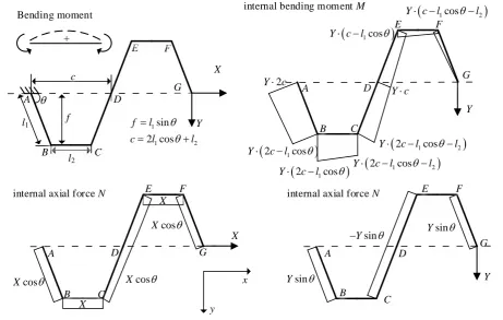
Corrugated panels may have different profiles, such as round, sinusoidal and trapezoidal. The stiffness matrix of the round corrugated panels has been built in the previous study (Wang et al. 2018). In this paper the trapezoidal corrugated is selected. In the 2-dimensional case, the profile of a trapezoidal corrugated panel has the periodic unit cell as shown in Figure1.
The corrugation unit consists of rigidly connected beams, labelled by the pointsA, B, ...,G. In the trapezoidal unit, the geometry variablesl1,l2,t,θ are used to describe the length of beamAB, the length of beamBC, the thickness of the panel and the internal angle of the trapezoid (0< θ≤90 ◦). The half height and half length of the corrugated panel are given by f and c, respectively. The width along the z
direction is denoted byw.
The internal loads in one trapezoidal unit are shown in Figure 1. Using classical beam theory, the deflections of pointGcan be obtained by accumulating the deflections of the other points (A,B, ...,F), including the rigid translations caused by the rotation angle of the beam cross section. The entire corrugated panel is then considered as an equivalent straight beam, which is fixed at one end and has the same deflection as the pointG. The method has been applied to find the deflections under a force in thexdirection (Wang et al. 2017). Using the same method, the deflections in response to the force in theydirection and the moment along the z direction have also been obtained. The deflection in thexdirection,u, the deflection in they deflection,v, and the rotation angle of the beam section about thezdirection,
α, can then be expressed by the equivalent properties of the
model as u v α = Ln EA 1 Kc 0 1 Kc L3 n
3EI +
1 Ksy L2 n 2EI 0 L 2 n 2EI Ln EI X Y M (1)
where the equivalent properties are
EA= 3 (2l1cosθ+l2)EI·EA
l2 1sin
2θ(2l
1+ 3l2)EA+ 3 (2cos2θl1+l2)EI EI= 2l1cosθ+l2
2l1+l2 EI
Kc=
EI
l1sinθ(l1+l2) (2l1cosθ+l2)n Ksy= 3
2
EI
l1l2(1−cosθ) (l1cosθ+l2)n
(2) The number of the corrugation units in the corrugated panel is given byn, and the length of the entire corrugated panel is given byLn. The Young’s modulus, area and second
moment of area are denoted as E, A and I respectively. It should be noted that the axial extension of the beam is taken into account when calculating the deflection in the x
direction.
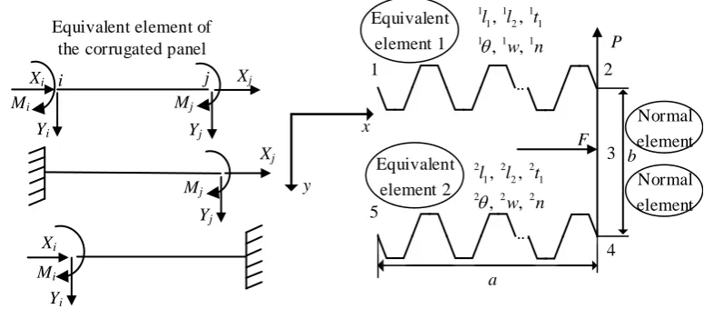
The equivalent beam element has two nodes,iandj, as shown in Figure2. According to Equations (1) and (2), the deflections of the two nodes can be obtained in response to the external loads. Thus, the stiffness matrix of the beam can be built by considering the equilibrium of the beam. For example, when nodejis constrained, the deflections of node
ican be written as
ui vi αi = Ln EA 1 Kc 0 1 Kc L3n
3EI +
1
Ksy −
L2n
2EI
0 − L
2 n 2EI Ln EI Xi Yi Mi (3)
Inverting this equation will give the external loads on nodei
as Xi Yi Mi = K11 ui vi αi (4)
Taking the equilibrium relationship of the beam element into consideration, we can obtain the loads at nodejas
Xj Yj Mj = K21 ui vi αi (5)
+ Bending moment
internal axial force N
X
cos
X Xcos
X X cos X B A C E F G D
internal axial force N
B A C E F G D B A C D E F G Y
2 1cos 2
Y c l l
2 1cos 2
Y c l l
2 1cos
Y c l
2
Y c
1cos
Y c l
1cos 2
Y c l l
2 1cos
Y c l
sin
Y Y
sin
Y
Ysin
internal bending moment M
Y c
X x y l1 l2 f c B A C D E F G 1 1 2 sin 2 cos f l
c l l
[image:3.595.66.528.61.354.2]Y
Figure 1. Internal loads of a trapezoidal corrugated panel
Xi Yi Mi Xj Yj Mj =
K11 K12 K21 K22
ui vi αi uj vj αj (6)
whereK12,K12,K21,K22are sub-blocks (three-by-three) of the stiffness matrix of the equivalent beam element.
As illustrated in Figure 2, the compliant structure is composed of three parts: two corrugated panels with different extension stiffnesses, which are modelled by two equivalent elements, and a connection part between them, which can be modelled by normal beam elements. The stiffness matrix of the compliant structure is then assembled to calculate its deformation. For the compliant structure, two sets of geometry parameters are needed, in which the superscripts 1 or 2 before the variables represent the two corrugated panels. The length and height of the structure are represented bya
andb. The actuation force and the concentrated aerodynamic force are represented byF andP respectively.Wang et al.
(2018) considered the effect of the aerodynamic load on the aeroelastic response of the wing tip device; since the aim of this paper is the physical demonstration of the concept in static tests and in the wind tunnel, the optimisation will only minimise the actuator force. Although the equivalent model has shown the relationship between the geometry variables and the equivalent properties explicitly, the optimisation is still necessary to determine the corresponding geometry variables in the upper and lower corrugated panels, especially
considering the requirements to induce the unsymmetrical stiffness and reduce the actuation force simultaneously.
Integration of the compliant structure into
the morphing wingtip
The structure of the morphing winglet consists of three main components: the leading edge, the compliant structure and the trailing edge, as shown in Figure 3. Since the model is mainly for demonstration, the NACA 0024 airfoil with a chord of 0.25m is used, considering manufacturing cost and convenience. The spanwise length of the structure,a, is 0.12m.
... x y 1 Equivalent element 1 2 3 4 5 Normal element Normal element F P a b Xj Yj Mj Xi Yi Mi Xj Yj Xi Yi
Mi Mj
i j
Equivalent element 2 Equivalent element of
the corrugated panel
...
1 1 1 1 2 1 1 1 1
, , , ,
l l t
w n
2 2 2
1 2 1
2 2 2
, ,
, ,
l l t
w n
[image:4.595.104.492.57.227.2]
Figure 2. Compliant structures based on trapezoidal corrugated panels
considering its convenience and availability. An end fairing is also added to provide an aerodynamic surface at the tip of the compliant structure.
Structural Optimisation
By employing the equivalent model, the calculation time for the compliant structure is reduced significantly, which leads to a faster optimisation. The compliant structure based on the unsymmetrical stiffness is optimised to reduce the actuation force, while the entire height of the compliant structure,B
(B=b+1l1sin1θ+2l2sin2θ), should be constrained to fit within the thickness of the airfoil. The ranges of the variables for the optimisation are
1,2l
1 0.01≤1,2l1≤0.025 m
1,2θ 0<1,2θ≤90o
1,2n 1≤1,2n≤4, 1,2n= 1,2...
1,2t 0.0015
≤1,2t≤0.005 m
(7)
The variables need to satisfy the geometry constraints, which are 1
2hactSf ≤b·Lact+ 1l
1sin1θ 1
2hactLactSf ≤b(1−Lact)− 2l
1sin2θ 1l
1sin1θ+2l1sin2θ≤0.75b 1t≤ 1
5 1l
1; 1t≤ 1 5
1l 2
2t≤ 1 5
2l 1; 2t≤
1 5
2l 2
2(1l1cos1θ)< a
2(1n) 2(2l1cos2θ)<
a
2(2n)
(8)
Here, the parameters hact, Sf and Lact correspond to the height of actuator, the safety coefficient preventing interference and the non-dimensional location of the actuator
(starting from 0 at node 2), respectively. These parameters are fixed in the optimisation with values of 0.02 m, 1.5 and 0.3. The two corrugated panels cannot have any interference so the sum of the heights, 1l1sin1θ+2l1sin2θ, should be smaller than the distance between them. The thickness of the corrugated panel should be small enough, compared to its length, so that classical beam theory can still be applied. The last constraint is applied to ensure the trapezoid does exist since the geometry parameterl2is not a variable in the optimisation.
The maximum von Mises stress, σv, in the compliant
structure should not exceed the yield stress of the material,
σy. Thus, another constraint is employed in the optimisation defined as
σv≤σy (9)
The yield stress is assumed to be 30MPa in the current study. The Young’s modulus of the material is 3GPa to simulate ABS plastic.
The MatlabR GA optimization toolbox (MATLAB
Compliant structure based on unsymmetrical stiffness Flexible
honeycombs
Flexible honeycomb structures in the trailing edge
[image:5.595.138.464.65.357.2]Linear actuator
Figure 3. The morphing wingtip demonstrator (the skin and fairing were not installed when the photograph was taken)
of the compliant structure is 0.0875 m in these optimisation cases.
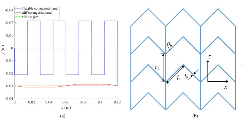
In the current study, the entire height of the compliant structure is 0.0524 m, and the width of the compliant structure accounts for around 35% chord, which starts at 15%. Minor modifications are made considering the installation and the other details, which are not the focus of this paper. The optimised variables and the equivalent properties of the corrugated panels are listed in Table 1
and the geometry is plotted in Figure 5(a). The results show that the optimisation provides a much more flexible upper corrugated panel compared to the lower panel, which introduces a significant stiffness asymmetry in the compliant structure. The thicknesses of both panels are at their lower bounds, indicating the requirement of the smallest actuation force. Also, it can be seen the entire height of the structure will be increased by 1l1 since the angle 1θ is around 90 degrees but2l1has almost no influence on the entire height due to the small2θ. The small angle in the lower corrugated panel also makes the lower aerodynamic surface almost flat. In this paper, no extra cover is added to the lower panel to simplify the manufacturing.
Leading and trailing edge solution
The leading and trailing edges of the airfoil are provided by the flexible honeycomb structure, as shown in Figure5(b). The equivalent modulus of the honeycomb in the transverse direction,Ex, has been derived in (Vocke III et al. 2011) as
Ex=Em
t
h lh
3 sinθ
h ch lhcos
2θh
[image:5.595.318.526.427.514.2](10)
Table 1. Optimised variables and properties of the compliant structure.
Upper corrugated panel Lower corrugated panel
1
l1 0.0213m 2l1 0.0115m 1
θ 89.98◦ 2θ 5.60◦
1
n 4 2n 1
1
t 0.0015m 2t 0.0015m
1
EA 54.975N 2EA 65513.226N
1
EI 0.0126Nm 2EI 0.0737Nm
A sequence of optimisations is performed to minimise the modulus. In addition to the geometry constraints, the constraint of the connection to the corrugated panels is also included: the number of honeycomb units should be an integer multiple of the number of corrugation units to ensure the honeycombs are evenly connected to the corrugated panels at both leading and trailing edges, and the loads can be transferred evenly through the structure.
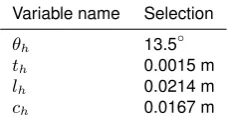
The final selection of the parameters of the flexible honeycomb structure is listed in Table2.
Table 2. Selected variables of the flexible honeycomb structures.
Variable name Selection
θh 13.5◦
th 0.0015 m
lh 0.0214 m
[image:5.595.367.481.709.770.2](a) (b)
Figure 4. (a)Optimised height and actuation force;(b)Compliant structure in the airfoil.
(a)
ch
lh
θh
th
z
x
…
(b)
Figure 5. (a)Optimised corrugated panels;(b)sketch of the honeycomb structures.
Experimental validation
Manufacture and static testing
The complex geometry obtained from the optimisation leads to problems in manufacturing, which is difficult using conventional methods often used for corrugated and honeycomb structures. Due to the development of 3D printing technologies, the geometry of the functional model may be manufactured using 3D printing, in which parts are fabricated by the selective deposition or fusing of materials layer by layer by computer-controlled machinery.
The two parts of the morphing wingtip were printed separately and then assembled and glued together due to the limitation of the maximum working size of the printer. Improvements have been obtained by using a larger 3D printer and a different type of printing method. In addition to the model made of ABS plastic, a model made of Polyamide was also manufactured using the selective laser sintering method (i.Materialise 2018). Polyamide has a higher tensile strength than ABS plastic but has a lower modulus than
ABS, which could lead to a larger change in the shape of the morphing structure.
Some modifications were made to the model with more rib-like supports provided in the leading and trailing edges. Since the main deformation of the compliant structure is extension or compression, the rib-like supports will not increase the actuation force since they are placed on the plane perpendicular to the axial deflections. The rib-like supports are also helpful to constrain the material during the printing, which can reduce the initial deformation. For the same purpose, some very thin columns are added between the upper and lower corrugation panels to prevent initial deformation, which are removed after printing.
[image:6.595.80.487.290.493.2]cannot be used due to the likelihood of damage during manufacturing and the requirement to carry local loads. A commercially available silicone rubber (SILEX LTD 2018) with 0.5mm thickness is employed after considering the maximum actuation force and other constraints.
The silicone rubber is cut to the size according to the model’s chord and span before it is bonded to the structure using adhesive. A cyanoacrylate adhesive (Permabond Engineering Adhesives 2018) is applied to the surface of the structure, which works for most plastic and rubber bonding. Since the silicone rubber is difficult to bond due to its stable characteristics, a primer is applied to the rubber surface to activate it. The structure and the silicone rubber are then assembled with a defined alignment direction. Some pressure is applied to avoid initial wrinkling. The procedure is performed by hand since the adhesive is instant, and takes only a few seconds to cure. The cured adhesive then needs 24 hours to reach its maximum strength. Safety procedures provided by the adhesives supplier were followed strictly during the whole operation and storage.
The linear actuator is installed into the morphing wingtip before the silicone rubber skin is bonded. The stroke of the actuator is 200mm, and the maximum actuation can be as large as 300N with a gear ratio of 256:1 (Actuonix Motion Devices Inc. 2018). The actuator is controlled by its own software with a control board. The extension of the actuator is given as a feedback signal.
Since the skin is bonded to the structure using the adhesive, it is not possible to remove the skin once it is bonded. Hence, two morphing wingtips are 3D printed: one made of ABS plastic and the other one made of Polyamide. Both the models have the same geometry.
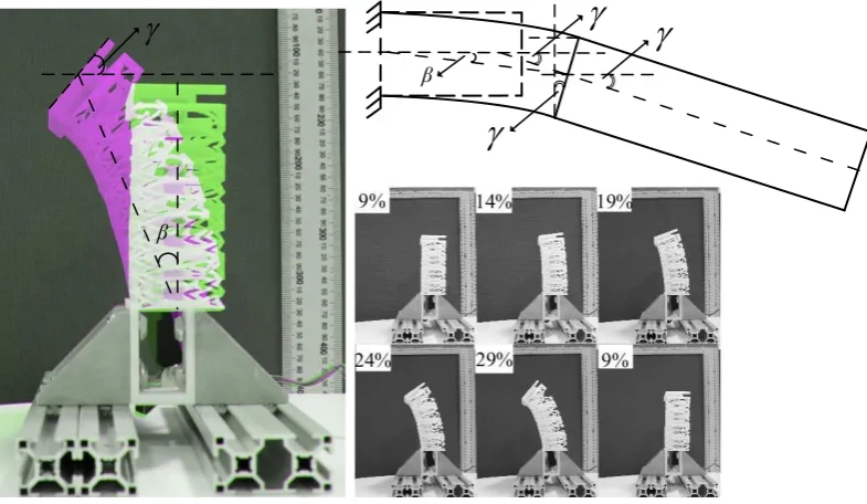
The model for the static test is made of ABS plastic, which is clamped to demonstrate the deflection as shown in Figure 6. No skin is bonded in the static test for the convenience of tests and installation. A 9% initial stroke is given to the actuator to reach its installation position, at which the compliant structure is not rotated. In the static test, the position of the actuator stroke varies from 9% to 29% and then back to 9%, which is recorded by a digital camera.
As shown in Figure 6, the stiffness asymmetry leads to a rotation angle of the compliant structure,β, as well as a change in the dihedral angle, γ, if the compliant structure works as a transition section connected to an outer fixed-geometry winglet. According to the fixed-geometry relationship, the introduced dihedral angle change γ is larger than the rotation angle β. The angles β and γ are measured from the photographs, and can be as large as 20 degrees and 45 degrees, respectively. While no skin is bonded to the structure, the static test has demonstrated the capability of the concept to change the shape of the wing.
Wind tunnel tests
The wind tunnel tests are performed in the Swansea University low-speed wind tunnel, which is a closed return circuit wind tunnel. The maximum air speed is 50 m/s, and the test section is 1 m high and 1.5 m wide. The analytical turbulence intensity and analytical flow uniformity is 0.175% and 0.04% respectively according to its operation manual, which is sufficient for the current study.
As shown in Figure7, a balance is installed on the bottom of main test section. A rotating frame is attached at the bottom of the test section, which can rotate the balance and the model as much as±90◦. The balance is a six-axis force plate, which can measure the three force components along the coordinate axes and three moment components about the three axes.
The wind tunnel is controlled by dedicated control software, which can read the outputs of the balance, change the airspeed and the rotation angle of the balance with a stepper motor. The wind tunnel model is installed vertically onto the balance. Thus the angle of attack of the model is changed when the frame rotates.
Figure 7 shows that the wind tunnel model is supported by two metal shafts. The shafts go through the bottom disc, but have no contact with it, which ensures the loads on the wall are not transferred to the balance. The bottom disc can rotate with the balance and the model, and the gap between the disc and the test section wall is sealed by an elastomer washer, which closes the test section and reduces the environmental influence. The shafts are clamped onto the balance. A gap, smaller than 0.5% of the span (Barlow et al. 1999) is provided between the bottom disc and the wind tunnel model, which makes the effect of the shafts negligible. The wind tunnel model used in the tests is shown in Figure
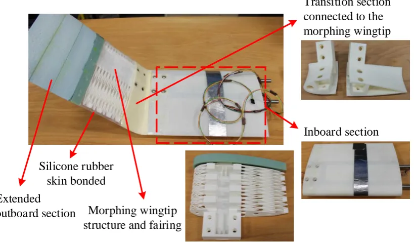
8. The model consists of the following components: the inboard section, the transition section, the morphing wingtip and the extended outboard section. All the components are manufactured by 3D printing except the extended outboard section, which is made of foam to reduce the weight and cost. The inboard section, transition section, and the morphing wingtip are assembled by nuts and bolts, which makes them replaceable.
The fixed-geometry inboard region helps to provide a steady inboard flow. And the transition section between the inboard section and the morphing wingtip can provide an initial dihedral angle to the wingtip. The morphing wingtip can also be installed directly onto the inboard section. In this case, the wind tunnel model has no initial dihedral angle, and the test results give the baseline results for the validation when the actuator does not cause any deformation. The extended outboard section is connected to the morphing wingtip using carbon fibre tubes. With the outboard section, the morphing wingtip works as a transition part to change the dihedral angle of a fixed winglet.
The spanwise lengths of the inboard section, the morphing wingtip and the outboard section are 0.35m, 0.15m and 0.15m respectively. No sweep angle or taper ratio is introduced to simplify the experiments. The NACA 0024 airfoil is used except for the small modification of the airfoil of the morphing wingtip. Aluminium foil tape is used to seal the gaps between the different sections and provide a smooth surface to the foam.
β
β
[image:8.595.97.490.56.284.2]
Figure 6. Static test demonstration when the actuator stroke position varies from 9% to 29%
Metal supports connected to
the balance
Clamping fixture Gap between
the model and the plastic disc
Balance Plastic disc Inboard section
Replaceable transition section/ morphing wingtip
Balance Step motor Rotating frame
Test section
x
[image:8.595.79.516.329.517.2]z
Figure 7. Wind tunnel setup and model installation
with different transition sections if necessary. Employing the transition section also makes the assembly of the morphing wingtip easier since the silicone rubber skin can be bonded to the transition section before the morphing wingtip is installed onto the inboard section.
The wind tunnel model without the transition section is tested first. The morphing wingtip made of ABS plastic is installed directly onto the inboard section, and silicone rubber is bonded to provide the aerodynamic surface. It should be noted that the morphing wingtip will lead to a curved spanwise change when the actuator extends or compresses the structure, which makes it difficult to validate the test results. Thus, the actuator does not deform the morphing wingtip for the baseline test, which leads to a wind tunnel model with zero dihedral angle.
The reference span is 0.65m, the reference area is 0.1625m2 and the test speed is 20m/s. The angle of attack varies from 0 to 10◦with a 2◦increment.
The control software of the wind tunnel takes the average value of the balance outputs and returns the differential pressure in the test section and the table angle as feedback of the wind tunnel status. Corrections to the measured data are performed considering solid and wake blockage corrections (Barlow et al. 1999). The blockage is found to be less than 0.7%. The corrections of the velocity and dynamic pressure are then performed to the measured data.
The test results are compared to the results from the numerical calculation using Tornado VLM (TVLM 2010), which is a vortex lattice method based software written in Matlab, and is sufficient and convenient for the low-speed cases. 280 panels are used to model the wing, providing sufficient accuracy.
Morphing wingtip
structure and fairing
Extended
outboard section
Inboard section
Transition section
connected to the
morphing wingtip
[image:9.595.98.508.61.300.2]Silicone rubber
skin bonded
Figure 8. Assembly and components of the wind tunnel model
(a) (b)
Figure 9. Comparison of the baseline wind tunnel test results(a)Lift coefficient,(b)Drag coefficient
changes the symmetry of the airfoil. Apart from the offset, the lift coefficient has the same trend compared to the numerical calculation. TVLM only calculates the induced drag, while the wind tunnel test will measure all the drag components. The ’zero-lift’ drag is estimated roughly using the measured drag coefficient when the angle of attack is 0, although there exists a small lift. Adding the ’zero-lift’ drag to the numerical calculated drag will provide a drag that is close to the wind tunnel test data, which at least shows a similar trend of the drag change. Generally, the wind tunnel tests of the baseline model provide reasonable results compared to the numerical calculation.
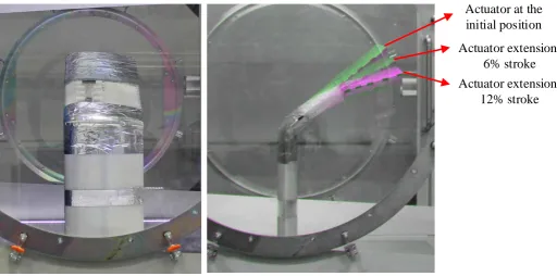
The test of the morphing wingtip is then performed with the transition section installed. The morphing wingtip model made of Polyamide is used. As shown in Figure 10, the actuator extension causes rotation of the morphing wingtip,
which increases the dihedral angle of outboard section. Estimation from the picture shows a 20◦ change of the dihedral angle can be achieved. Although an even larger angle change can be obtained, the actuator extension is limited to 12% of the stroke to ensure the morphing wingtip does not fail in the test. Since the rotation comes from the differential extensions of the compliant structure, the actuator will not compress the compliant structure and thus avoid buckling of the skin.
[image:9.595.82.502.354.544.2]Actuator at the
initial position
Actuator extension:
6% stroke
[image:10.595.52.565.55.309.2]Actuator extension:
12% stroke
Figure 10. The wind tunnel model: (a) Front view, and (b) Side view with different the actuator extensions
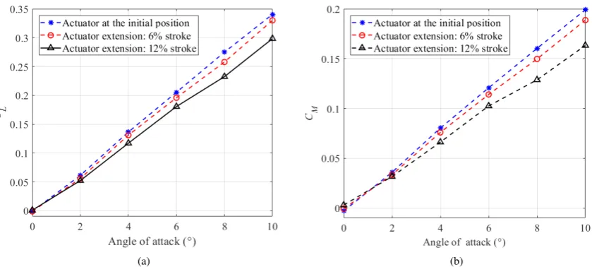
moment measured by the balance is based on the reference plane located at the centre of the balance, and hence the rolling moment is overestimated. The reductions in the lift coefficientCL and the rolling moment coefficient CM are demonstrated in the test. For example, when the angle of attack is 6◦, a 12% reduction of CL and a 15% reduction of CM can be obtained if the actuator extension is 12% of the stroke. Comparing the results for different actuation extensions shows that the reduction of the aerodynamic loads can be increased when the actuator causes a larger shape change.
Conclusion
In this paper, the development of a morphing wingtip based on compliant structures is introduced. Rotation deformation of the compliant structure can be induced by a linear actuator, and the compliant structure is integrated into an airfoil.
Trapezoidal corrugated panels are used in the compliant structures. An equivalent model of the corrugated panel is built, which is expressed by its stiffness matrix. The equivalent model is applied in the optimisation to find the optimised stiffness allocation in the structure. To fit within the thickness of the airfoil, a sequence of optimisation cases is performed to find the optimised height of the compliant structure. To provide the airfoil shape, flexible honeycomb structures are used in the leading and trailing edges, which are evenly connected to the corrugated panels after the optimisation of the honeycomb structures is performed. The result is an extreme stiffness asymmetry, which has three orders of magnitude difference between the stiffness of the upper and lower panels and explains the minimal actuation force. The result also highlights the influence of the unsymmetrical stiffness, and shows its capability of changing the wing shape in the tests.
A demonstration model is manufactured, and the static tests validate the deformation of the model, which is driven by a linear actuator. The rotation angle is recorded while a larger dihedral angle is found if the proposed model works as a transition section connected to a outer fixed-geometry winglet, which shows a promising structural solution for a morphing winglet. The wind tunnel test of the demonstration model validates the potential of the morphing wingtip in a low-speed flight condition. A baseline test is first performed with zero dihedral angle, and the measurements compared to numerical predictions. The test of the morphing wingtip model shows that the aerodynamic performance is affected as the actuator changes the dihedral angle.
A commercially available silicone rubber is employed to provide the aerodynamic surface in the paper since the focus is the compliant structure. However, better solutions could be found in the future work. For example, the elastomer skin could be provided by fabricating a sleeve-like covering for the compliant structure using a 3D printed mould. The covering could stretch over the compliant structure, providing a complete covering without seams, and could be designed to incorporate internal details.
(a) (b)
Figure 11. Change of(a)CL,(b)CMcaused by the morphing wingtip
Acknowledgements
Chen Wang would like to thank the China Scholarship Council (CSC) and the College of Engineering of Swansea University for providing his PhD scholarship.
References
Actuonix Motion Devices Inc (2018) ACTUONIX P16-P Linear Actuator With FeedBack. URL https://www. actuonix.com/P16-P-Linear-Actuator-p/ p16-p.htm.
Barlow JB, Rae WH and Pope A (1999)Low-Speed Wind Tunnel Testing. Third edition. Wiley. ISBN 978-0-471-55774-6. Bilgen O and Friswell MI (2012) Implementation of a
continuous-inextensible-surface piezocomposite airfoil.Journal of Aircraft
50(2): 508–518.
Bubert EA, Woods BKS, Lee K, Kothera CS and Wereley NM (2010) Design and fabrication of a passive 1d morphing aircraft skin. Journal of Intelligent Material Systems and Structures
21(17): 1699–1717.
Campanile LF (2005) Initial thoughts on weight penalty effects in shape-adaptable systems. Journal of Intelligent Material Systems and Structures16(1): 47–56.
Castrichini A, Siddaramaiah VH, Calderon D, Cooper J, Wilson T and Lemmens Y (2017) Preliminary investigation of use of flexible folding wing tips for static and dynamic load alleviation.The Aeronautical Journal121(1235): 73–94. Daniele E, De Fenza A and Della Vecchia P (2012) Conceptual
adaptive wing-tip design for pollution reductions. Journal of Intelligent Material Systems and Structures23(11): 1197– 1212.
Dayyani I, Haddad Khodaparast H, Woods BKS and Friswell MI (2015) The design of a coated composite corrugated skin for the camber morphing airfoil. Journal of Intelligent Material Systems and Structures26(13): 1592–1608.
Dimino I, Amendola G, Amoroso F, Pecora R and Concilio A (2016) Morphing technologies: Adaptive ailerons. In: Agarwal RK (ed.) Recent Progress in Some Aircraft Technologies, chapter 05. Rijeka: InTech. DOI:10.5772/63645. URLhttp: //dx.doi.org/10.5772/63645.
Ermakova A and Dayyani I (2017) Shape optimisation of composite corrugated morphing skins. Composites Part B: Engineering
115: 87 – 101. DOI:http://dx.doi.org/10.1016/j.compositesb. 2016.10.029. Composite lattices and multiscale innovative materials and structures.
Falco L, Gomes AA and Suleman A (2011) Aero-structural design optimization of a morphing wingtip. Journal of Intelligent Material Systems and Structures22(10): 1113–1124.
Gatto A, Mattioni F and Friswell MI (2009) Experimental investigation of bistable winglets to enhance aircraft wing lift takeoff capability.Journal of Aircraft46(2): 647–655. iMaterialise (2018) 3D printing material: Polyamide.
URL https://i.materialise.com/ 3d-printing-materials/polyamide.
Karagiannis D, Stamatelos D, Spathopoulos T, Solomou A, Machairas T, Chrysohoidis N, Saravanos D and Kappatos V (2014) Airfoil morphing based on sma actuation technology.
Aircraft Engineering and Aerospace Technology86(4): 295– 306. DOI:10.1108/AEAT-10-2012-0194.
MATLAB Global Optimization Toolbox (R2016) Matlab global optimization toolbox. The MathWorks, Natick, MA, USA. Nagel C, Fiedler A, Schorsch O and L¨uhring A (2015) Design,
manufacture, and testing of a seamless morphing concept for a smart aircraft wingtip. In: Proceedings of the 7th ECCOMAS thematic conference on smart structures and materials (SMART 2015), Ponta Delgada, Azores, submitted Google Scholar. Ponta Delgada, Azores.
Olympio KR and Gandhi F (2010) Flexible skins for morphing aircraft using cellular honeycomb cores. Journal of Intelligent Material Systems and Structures 21(17): 1719–1735. DOI: doi:10.1177/1045389X09350331.
Permabond Engineering Adhesives (2018) Permabond Engineering Adhesives. URL http://www.permabond.co.uk/ cyanoacrylates.
SILEX LTD (2018) Silex Superclear Silicone Sheet. URLhttp: //www.silex.co.uk/.
TVLM (2010) A vortex lattice method implemented in matlab. URLhttp://tornado.redhammer.se/.
Vocke III RD, Kothera CS, Woods BKS and Wereley NM (2011) Development and testing of a span-extending morphing wing.
Journal of Intelligent Material Systems and Structures22(9): 879–890. DOI:10.1177/1045389X11411121.
Wang C, Haddad Khodaparast H and Friswell MI (2016) Con-ceptual study of a morphing winglet based on unsymmetrical stiffness. Aerospace Science and Technology 58: 546–558. DOI:http://doi.org/10.1016/j.ast.2016.09.015.
Wang C, Haddad Khodaparast H, Friswell MI and Shaw AD (2017) An equivalent model of corrugated panels with axial and bending coupling. Computers & Structures183: 61–72. DOI:http://doi.org/10.1016/j.compstruc.2017.01.008.