Locomotion for Crowd Animation
by
Martin Praºák
A dissertation submitted to the University of Dublin, Trinity College in fulllment of the requirements for the degree of
Doctor of Philosophy
Declaration
I declare that this thesis has not been submitted as an exercise for a degree at this or any other university and that unless stated, it is entirely my own work.
I agree that the library may lend or copy the thesis upon request. This permission covers only single copies made for study purposes, subject to normal conditions of acknowledgement.
Summary
Real-time computer animation is an essential part of modern computer games and virtual reality applications. While rendering provides the main part of what can be described as visual experience, it is the movement of the characters that gives the nal impression of realism. Unfortunately, realistic human animation has proven to be a very hard challenge.
Some elds of computer graphics have a compact and precise mathematical description of the underlying principles. Rendering, for example, has the rendering equation, and each realistic rendering technique provides its approximate solution. Due to its highly complex nature, character animation is not one of these elds. That is one of the reasons why even single character animation still provides signicant research challenges. The challenges posed by a crowd simulator, required to populate a virtual world, are even larger. This is not only because of the large number of simultaneously displayed characters, which necessitate the use of level-of-detail approaches, but also the requirement of reactive behaviour, which can be provided only by a complex multi-level planning module.
In this thesis, we address the problem of human animation for crowds as a component of a crowd simulator.
To ensure that we start with realistic animation data, we record our data using a camera-based passive optical motion capture system. We provide a detailed description of our camera setup, our human body model and our rened pipeline, which together allow for robust and precise human motion reconstruction and its usage in a real-time system.
While the captured motion data provide an accurate representation of human motion, their direct usability in a real-time system is limited to a simple playback of the original clip on a human model with body proportions corresponding to that of the original actor. To overcome this limitation, a data-driven animation synthesis method has to be incorporated to create novel animations based on the source data. The solution described in this thesis uses a parametric data-driven locomotion synthesis model, with particular focus on motion synthesis for crowds. This description includes motion preprocessing, periodisation, parametric motion blending structure and its integration with a high-level behaviour module.
Acknowledgements
Unfortunately, the acknowledgments section is not long enough to mention all the people who helped me on this long journey. Therefore, to begin with, I want to thank all my friends, atmates, family, colleagues and fellow students, and everybody else who I met on the way. Even if I don't mention your name here, I want you to know that I am grateful.
On a personal note, I would like to thank Giulia for the very unreasonable amount of support, shelter, plans, love and pasta I would not have been able to go this far without you. Then my atmates, Bartosz, Suule and Princess, with all their ideas, stories and distractions thank you for all the sweets you didn't eat. Finally, I can't forget to mention Lucka for her occasional invasions into my life, and, of course, the unconditional support of Juli and Lisa - thug je che!
In the academic world, I was fortunate to have Prof. Carol O'Sullivan as my supervisor. Her invaluable advice and support guided me through the labyrinth of research, and allowed me to explore concepts and ideas I would never have explored by myself. My examiners, Dr John Dingliana and Dr Ronan Boulic, provided a very professional assessment of my work during and after my viva, and helped to rene this dissertation into its nal form. Dr Ladislav Kavan and Dr Daniel Sýkora showed me the way in their respective elds, which form the very basis of a large part of my work. And nally, I couldn't forget to mention Dr Rachel McDonnell, Dr Ludovic Hoyet, Colin Fowler, Jiang Zhou, Tom van Eyck, Dr Cathy Ennis, Dr Micheal Larkin and all the other members of GV2, as without their help this thesis wouldn't have been possible.
Publications
Related Publications
1. Prazak, M., McDonnell, R., Kavan, L., & O'Sullivan, C. (2008). Towards a perceptual metric for comparing human motion. In Poster proceedings of the ACM SIGGRAPH/Eurographics symposium on Computer animation (pp. 1314)
2. Prazak, M., McDonnell, R., Kavan, L., & O'Sullivan, C. (2009). A perception-based metric for comparing human locomotion. In Proceedings of the 9th Irish Workshop on Computer Graphics (pp. 7580)
3. Ruttle, J., Manzke, M., Prazak, M., & Dahyot, R. (2009). Synchronized real-time multi-sensor motion capture system. In ACM SIGGRAPH Asia 2009 Sketches & Posters (pp. 1619)
4. Prazak, M., Kavan, L., McDonnell, R., Dobbyn, S., & O'Sullivan, C. (2010a). Moving crowds: A linear animation system for crowd simulation. In Poster Proceedings of the ACM SIGGRAPH Symposium on Interactive 3D Graphics and Games
5. Prazak, M., McDonnell, R., & O'Sullivan, C. (2010b). Perceptual Evaluation of Human Anima-tion Timewarping. In ACM SIGGRAPH Asia 2010 Sketches (pp. 30:130:2)
6. Prazak, M., Hoyet, L., & O'Sullivan, C. (2011). Perceptual evaluation of footskate cleanup. In Proceedings of the ACM SIGGRAPH/Eurographics symposium on Computer animation (pp. 287294)
7. Prazak, M. & O'Sullivan, C. (2011). Perceiving human motion variety. In Proceedings of the symposium on Applied Perception in Graphics and Visualization
Other Publications
Contents
1. Introduction 15
1.1. Motivation . . . 16
1.2. Scope . . . 17
1.3. Methodology . . . 17
1.4. List of Contributions . . . 18
1.5. Summary of Chapters . . . 20
2. Background and Related Work 21 2.1. Motion Data Representation . . . 22
2.2. Character Skinning . . . 25
2.3. Motion Editing . . . 28
2.4. Capturing and Storing Motion Data . . . 34
2.5. Data-driven Animation Methods . . . 36
2.6. Motion Metrics . . . 44
2.7. Perception of Motion . . . 49
3. Motion Capture Pipeline 55 3.1. Camera Setup . . . 55
3.2. Calibration . . . 57
3.3. Capturing Human Locomotion . . . 58
3.4. Human Skeleton Model . . . 58
3.5. Canonical Software Interface . . . 59
4. Footstep Constraints 65 4.1. Feet Motion Capture . . . 66
4.2. Anatomy of a Footstep . . . 67
4.3. Footstep Detection . . . 68
4.4. Footstep Constraints Enforcement . . . 83
5. A Linearised Locomotion System for Crowd Animation 91 5.1. Overview . . . 92
5.2. Motion Map Concept . . . 93
5.3. Data Preprocessing . . . 98
5.4. Behaviour Animation Interface . . . 101
5.5. Parametric Space Concept . . . 103
5.6. Linearised Animation . . . 107
6. Perceptual Studies 113
6.1. A Human Locomotion Comparison Metric . . . 114
6.2. Crowd Motion Variety . . . 121
6.3. Footskating and Footskate Cleanup . . . 128
6.4. Human Locomotion Timewarping . . . 136
6.5. Conclusions . . . 138
7. Conclusions 141 7.1. Contributions . . . 141
7.2. Limitations and Future Work . . . 142
7.3. Final Remarks . . . 144
Bibliography 145
A. Matrix Algebra for Skeletal Character Animation 157
B. Least Squares 3D Plane Fit 161
List of Figures
1.1. Metropolis crowd simulation system. . . 16
1.2. The Biodancer installation screenshots. . . 18
2.1. Linear interpolation of transformation matrices . . . 23
2.2. The illustration of the artifacts of simple linear skinning . . . 27
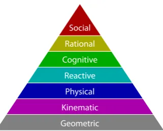
2.3. Behaviour pyramid, illustrating the levels of abstraction used in behavioural simulation 43 3.1. Detailed view of our motion capture hardware . . . 56
3.2. Top and perspective views of our camera setup during the motion capture process . . 56
3.3. Coverage of our camera setup . . . 57
3.4. Guiding trajectories for locomotion capture . . . 58
3.5. Original Vicon markerset with 43 markers compared to our markerset with 55 markers 59 3.6. Vicon to 3DS MAX animation converter software . . . 60
3.7. The pipeline for Metropolis project characters animated using NaturalMotion Mor-pheme software . . . 61
4.1. Footstep enforcement pipeline . . . 65
4.2. The foot bones and their representation in our optical motion capture . . . 66
4.3. Foot markers placement and naming in our capture pipeline . . . 67
4.4. Non-rigidity tting artifact of skeletal motion capture data . . . 68
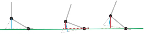
4.5. The description of dierent stages of a footstep . . . 68
4.6. XYZ plot of joint trajectories during locomotion . . . 69
4.7. The y (up) component of the foot marker trajectory data during a footstep . . . 69
4.8. The x-z and y axis separation of joint data for two dierent locomotions . . . 70
4.9. A comparison between the y axis data of the joints and closest markers . . . 70
4.10. An illustration of the input signal dierentiation causing an increase in the noise levels 71 4.11. Result of ltering the y ankle signal using a discrete Gaussian lter . . . 72
4.12. Result of ltering the y ankle signal using a median lter . . . 73
4.13. Result of ltering the y ankle signal using a bilateral lter . . . 74
4.14. The illustration of the y axis thresholding constraint detection approach . . . 75
4.15. A detailed view on a single footstep detected using XZ position thresholding . . . 76
4.16. Velocity magnitude (speed) graph of one foot during straight walking motion . . . 77
4.17. Detail of a footstep in the speed graph . . . 78
4.18. A graph of joint speeds for dierent types of locomotion . . . 78
4.19. An illustration of the circle t into noisy data . . . 78
4.21. Rotation centre analysis of the XZ-Y separated trajectory data as a constraint detection
method . . . 79
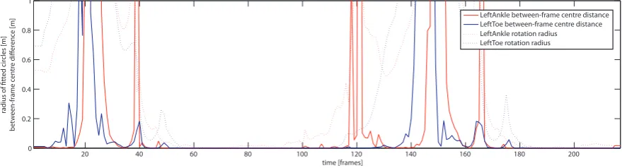
4.22. The radii of detected circles in footstep data . . . 79
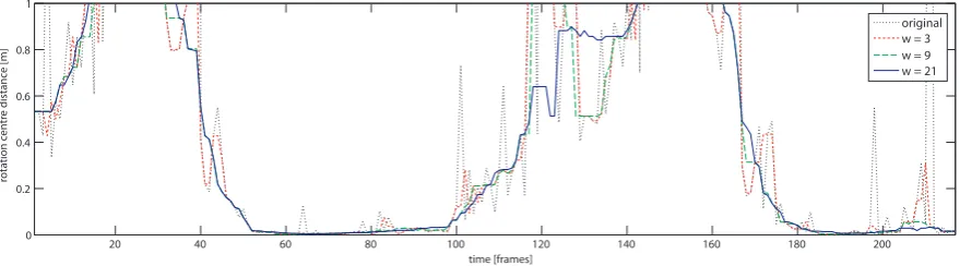
4.23. The impact of dierent tting window width on the detected circle diameters . . . 79
4.24. The median ltering of the circle diameters . . . 80
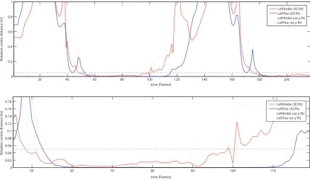
4.25. The comparison of the xz-y separation to the rotational axis detection . . . 80
4.26. A comparison between XZ-Y separation method and the rotation axis method . . . . 81
4.27. An example of between-frame rotational centre distance function on footstep data . . 82
4.28. An example of binary median ltering of the output constraint data with noise . . . . 82
4.29. The skeleton miscalibration artifact . . . 83
4.30. Methods of addressing the feet miscalibration artifact . . . 84
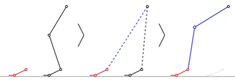
4.31. Limb-lengthening solution for footstep constraints . . . 88
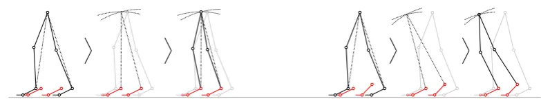
4.32. The naive rootx solution for footstep constraints . . . 89
4.33. XZ-Y separate rootx solution . . . 89
5.1. The overview of our data-driven locomotion system . . . 92
5.2. The motion maps visualisation overview . . . 94
5.3. A comparison of metric functions, showing their impact on the resulting motion map . 95 5.4. An illustration of the eects of applying a normalised smoothing lter to a motion map 96 5.5. A comparison of 2D Gaussian smoothing with the eects of the diagonal smoothing approach . . . 97
5.6. An example of period detection using the periodic smoothing approach . . . 98
5.7. An illustration of histogram equalisation on a motion map generated from a dancing sequence . . . 99
5.8. Illustration of the footsliding artifacts as a result of period dierence frame blending . 99 5.9. An illustration of dierent trajectory extraction methods . . . 100
5.10. The idealised trajectory extraction, demonstrated on a turning locomotion . . . 101
5.11. Limited and damped PD controller (behaviour interface) path following examples . . . 102
5.12. The artifacts of the PD controller as a behaviour animation interface . . . 103
5.13. The parametric space structure and the region of inuence of one clip . . . 104
5.14. An example motion clip generated by a sequence of parameter changes inside the para-metric space . . . 105
5.15. The inaccuracies caused by the linear blending scheme and the corrective step that alters the length interpolation method . . . 106
5.16. Demonstration of errors introduced by our blending method . . . 109
5.17. A combination of a pre-simulated mesh animation with a skeletal animation . . . 111
5.18. Results of the performance tests of our blending method and the resulting animation system . . . 112
6.1. Layout of the locomotion metric perceptual experiment . . . 115
6.2. Results of the classication performed on the data obtained in the perceptual experiment117 6.3. Graphical representation of the data obtained in our perceptual experiment . . . 118
6.4. The components of a composite metric based on two periodic animation . . . 120
6.5. Mannequin character building steps . . . 123
List of Figures
6.7. Scenario trajectory optimisation . . . 124
6.8. The experiment stimuli and their creation . . . 125
6.9. The selection of motion clips based on actors' body shapes . . . 126
6.10. Results from the experiment on the perception of crowd variety . . . 127
6.11. Illustration of the footstep cleanup and parameterised footskate introduction used in our experiments . . . 129
6.12. Stimuli example for the baseline experiment . . . 131
6.13. Results of the baseline experiment . . . 132
6.14. Stimuli example for the footskate cleanup experiment . . . 133
6.15. The main eect of comparison factor on trials where corrected motions (K or L) were presented together with uncorrected ones (U) . . . 134
6.16. The main eect of footsliding level factor on trials where corrected motions (K or L) were presented together with uncorrected ones (U) . . . 135
6.17. Lengthening correction method is preferred over Kovar's when displayed simultaneously 136 6.18. The timewarping experiment stimuli . . . 137
6.19. Results of the timewarping experiment . . . 138
1
Introduction
Through the inuence of the entertainment industry, virtual reality and articially created environ-ments became a part of our daily lives. With the help of modern computer graphics, artists can express their visions in virtual worlds with limitless potential. Advances in rendering methods allow these worlds to become extremely believable; particularly so in movies, where even very complex mod-els of physical behaviour can be implemented, and every little aspect can be dened in advance and fully controlled by the artist. But even recent games and virtual reality applications, operating under very limiting constraints of responsiveness and high framerates, can provide a real-time immersive experience very close to that of the lm world.
However, to complete the illusion of a living world, impressive visual scenes are not enough they need to be inhabited by virtual humans, which in turn have to be moving and interacting, both with the environment and among themselves. For certain purposes, we need many humans from dozens to simulate a tourist group, through thousands to create a protest march or a virtual army, up to millions if we want to recreate whole cities.
The movie industry oers many interesting examples of large crowds. Older movies, such as The Last Emperor (1987) or Stargate (1994) would employ thousands of actors to create their crowd scenes. However, the same eect and much more can be achieved using computer graphics (CG), with signicant savings in eort, nance and manpower. CG can create a large variety of crowd scenarios from highly-stylised crowds (I, Robot, 2004; Antz, 1998), through fantasy-like humanoid characters (Lord of the Rings Trilogy, 2001-2003; the Chronicles of Narnia, 2005), up to very realistic crowds in a stylised environment (Inception, 2010) or during natural disasters (2012, 2009).
Figure 1.1.: Metropolis crowd simulation system.
small size of individual characters simplies the task signicantly. Several recent games employ crowds in the most natural and challenging 1st (or close 3rd) point of view (e.g., Assassins Creed I and II). While extremely impressive considering the level of crowd interaction and real-time framerates on common hardware, these games also demonstrate the shortcomings of current state-of-the-art crowd techniques, such as the lack of responsiveness and animation artifacts.
The main topic of this thesis is to address the animation aspects of crowd simulations, creating an entire city of realistically moving characters in real times. Naturally, in a city simulation, most of these characters will be walking, hence the focus on the locomotion of humanoid gures. Our system should be capable of providing an artifact-free animation for each individual character based on example animation data (with a very low computational cost), while providing an ecient interface to the behaviour module and the necessary animation variety.
1.1. Motivation
As the eld of data-driven character animation matures, its methods provide increasing levels of animation realism for single characters. Several distinct groups of methods evolved, each with its own specic set of properties and limitations (see Section 2.5). However, a large majority of these methods either scale linearly with the number of characters, with a relatively large computational cost for every character, or do not allow the necessary animation variety required for a crowd. This is an important issue, as the number of characters in a crowd can be very high. However, not all of them will be visible at high detail all the time; an aspect described in the rendering systems as level of detail (LOD).
Therefore, we aim to create a data-driven crowd animation model eective enough to animate a large crowd, in a level of detail high enough to provide realistic animation, but at the same time low enough to avoid any unnecessary computation. Moreover, the computational and storage costs required for storing a new characteristic animation style should be minimised, with the style creation automatised as much as possible. Lastly, the animation should be responsive, to enable interactive crowd simulations that are inuenced by the user.
1.2. Scope
1.2. Scope
In this thesis, we focus on the animation aspects of human locomotion and their perceptual properties, in the context of crowd animation synthesis.
Apart from an animation module, a typical crowd system has to include high level behaviour and rendering components. However, these latter two topics are not within the scope of this thesis; we only describe the layers connecting them to our animation system. For behaviour, we assume the existence of a system that provides the position and velocity of every character for every frame, with values within a range natural for a human actor. The rendering should be performed by a state of the art hardware accelerated graphics engine, that describes the character's deformation using a set of 4x3 matrices.
Even though we use a certain amount of procedural animation editing, our model is primarily data-driven and requires a motion database as its input. These data are captured using our passive optical motion capture system, a description of which is included. While other data sources for our animation model are possible, they are not described as a part of this thesis. We assume that the data do not contain explicit constraints information (e.g., footstep timing and positions), and therefore require a constraints detection step to be performed during a preprocessing stage.
Apart from the behaviour and rendering modules, we assume that a level of detail (LOD) system is in place, which separates the visible crowd into several groups with dierent display and animation accuracy requirements. As such a system is a standard part of either behaviour or rendering module (or a combination of both) of a crowd simulator, this is a generalisable assumption. The main part of our work is focused on the middle level of detail characters, with characters large enough to be individually recognisable, but small enough for the animation not to require an excessive level of accuracy. Generally, the high LOD characters are in the foreground, usually numbering less than 100; the middle level of detail characters can number up to several thousand; and the low level of detail, with characters spanning no more than several pixels of the screen, can be animated using a very simple model.
As our perceptual experiments are designed to answer questions arising from the technical and imple-mentation aspects of the thesis, we use only humanoid characters as the experiment stimuli. However, their representation varies depending on the type of the experiment from a simple stick-gure, through a wooden mannequin to a realistic skinned human model. The number of simultaneously displayed characters also varies depending on the experiment goal from a single character to a group of 25.
While we limit our scope mainly to crowd animation, almost all developed techniques and established perceptual properties apply to single character animations as well. For a list of limitations of our implementation and results please refer to Section 7.2.
1.3. Methodology
In a similar way to the rest of the thesis, our methodology can be separated into the implementation and technical part, and the techniques used for the design and evaluation of perceptual experiments.
1.3.1. Implementation Methodology
Figure 1.2.: The Biodancer installation screenshots.
rigorously by performing a formal perceptual experiment.
The implementation uses exclusively the C++ programming language, extensively incorporating the Standard, Boost, OpenGL and Wild Magic libraries. A large number of other libraries were used for specic tasks, such as ANN (Approximate Nearest Neighbour), SDL (Simple DirectMedia Layer), wxWidgets, TinyXML, FreeImage and NaturalMotion Morpheme. With the exception of the Metropolis project, all development was done in the Linux operating system (Ubuntu, Debian), using the GCC compiler and the CMake building system. To allow the use of the run-time system inside the Metropolis project, a part of the developed code was ported to the MS Windows and Visual Studio 2005 compiler. The visualisation of the algorithms' results, both for debugging purposes and for perceptual experimentation, also includes several GLSL shaders.
1.3.2. Perceptual Experiments and Evaluation
All the perceptual experiments presented in this thesis use standard methods developed in the eld of psychophysics. The procedures (tasks) used are variations of the standard n-alternative or n-interval forced choice task, where several stimuli are presented, separated either spatially or temporally, on a computer screen (please see the description included in each experiment section for more details).
The majority of the experiments use the method of constant stimuli, where a combination of pre-sented stimuli are selected from a set of pre-generated examples. Each possible combination of the tested factors, as represented in the example database, is shown to the user several times, leading to a reliable measure of the responses. The signicance of the results is tested using a repeated mea-sures analysis of variance (ANOVA), with a post-hoc analysis using the Newman-Keuls comparison of means, or by performing the standard t-test. All the presented graphs show the average values for signicant factors and their standard error.
For the particular purpose of accurate threshold estimation in the footskating experiments (see Section 6.3.2), we employ the adaptive staircase method. Its evaluation is performed by tting a psychometric curve to the results, with the point of subjective equality (PSE) and just-noticeable dierence (JND) parameters determined from the curve shape.
1.4. List of Contributions
The contributions of this thesis can be separated into three groups, which consist of three dierent aspects of the research.
The rst group, technical contributions, focuses on the development of a framework for large crowd animation. The contributions include:
1.4. List of Contributions
a camera setup (Section 3.1),
an anatomically-based human body model (Section 3.4), a novel constraints detection algorithm (Section 4.3), and
a pipeline for converting motion capture data to a format usable in motion editing software (Section 3.5);
a novel data-driven animation system (Chapter 5), aiming in particular at large crowd anima-tions. Its parts are:
motion preprocessing (Sections 5.2 and 5.3), editing the source animations and making them periodic,
a classication scheme (Section 5.3.3), registering each input animation based on its tra-jectory,
a parametric model (Section 5.5), and related blending scheme (Section 5.6), and
a behaviour interface (Section 5.4), connecting the animation system with a higher level planning module.
The second group, perceptual metrics, provides a set of metrics and recommendations aimed in particular at data-driven crowd simulations. It is separated into four sections, each describing a set of experiments, their setup, evaluation and results:
The human locomotion comparison metric (Section 6.1) provides insights into the way people dierentiate between locomotions and identies which features provide the largest amount of information to do so,
the crowd motion variety experiment (Section 6.2) determines the minimal number of dierent characteristic animations required for a group of walking characters to appear varied,
the footskating perception experiments (Section 6.3) determine the saliency of this common artifact and evaluate ways to address it in a perceptually consistent manner, and
the human animation timewarping experiment (Section 6.4) shows that the eects of timewarp-ing, one of the simplest and most common methods for animation edittimewarp-ing, are not symmetrically distributed around zero.
While all these experiments are aimed to be used to tune our crowd animation system, their setup is independent of the implementation, making the result generalisable to any crowd / animation system. The last group of contributions contains implementation outputs code base, programs and data created during the course of this research:
the motion editing library, which is the foundation of all programs, demos and experiment frameworks described in this thesis. It includes a large collection of algorithms, data structures and data importers/exporters,
the experimental frameworks, each described in its respective section of Chapter 6,
the data converter, a GUI application capable of converting data between our motion capture system, our modelling software and our runtime framework,
the motion editor, a command-line application allowing advanced manipulations of motion data, the Biodancer Installation (Figure 1.2), an interactive installation presented in the Science
Gallery during the Biorhythm exhibition,
the Metropolis Animation System (Figure 1.1), a crowd animation module integrated into a full crowd simulation system, and
and heights from 1.53 to 1.96m.
1.5. Summary of Chapters
The remainder of this thesis is structured as follows:
Chapter 2 provides an overview of the previous work related to the topic of this thesis. Chapter 3 describes the process of motion capture, aimed in particular at the passive
opti-cal motion capture pipeline. We provide details of the camera and capturing volume setup, calibration, the developed marker setup and connected human model, and a novel method for constraint detection.
Chapter 4 deals with description of the most important constraint type required for locomotion synthesis, i.e., the footsteps. We analyse several previous approaches and suggest a new method, applicable to both skeletal and marker data.
Chapter 5 provides details of our crowd animation module. It includes the description of: the motion map concept, used for determining the properties of the input motions, data preprocessing step,
the parametric blending scheme,
linearised skinning method based on the properties of the blending scheme, and details of the animation module integration into a full crowd simulation system.
Chapter 6 summarises the perceptual experiments we performed in relation to the topic of this thesis, including
a perceptually-based human locomotion metric, allowing to compare the characteristics of human locomotion (Section 6.1),
the requirements of animation variety for a crowd scene (Section 6.2),
the impact of footskating and footstep cleanup (the most common locomotion artifact; Section 6.3), and
the impact of timing changes on the levels of a motion being perceived as realistic (Sec-tion 6.4).
2
Background and Related Work
The area of human character animation is an important part of computer graphics, and as such it received a lot of attention from the start. The corpus of previous work is therefore very large and its full account is beyond the scope of this thesis. The following chapter contains a description of previous work directly inuencing the development of ideas contained in this thesis.
A brief overview of the content of each section and its relation to the rest of the thesis can be listed as follows:
Motion data representation plays a crucial role in storage, data handling and interpolation. In Section 2.1, we provide a brief overview of common representations, with a focus on joint-based (skeletal) methods. Throughout the thesis, we use mainly the matrix form (see Section 2.1.2), but other techniques are used for specic tasks (e.g., rotation interpolation using quaternions, axis-dependent joints using Euler angles).
The nal goal is to use skeletal data to drive a human character represented as a polygonal mesh using a process called skinning (see Section 2.2). This topic is also closely related to our linear mesh deformation technique to speed-up the animation generation in a parametric space (see Section 5.6).
Motion editing techniques are necessary for both altering captured motion and creating data-driven animation models (Section 2.3). They are used in both contexts throughout this thesis (Section 4.4 and Chapter 5). As constraint-based methods are part of the motion editing eld, an overview of constraints detection (closely related to Chapter 4) is provided as well.
Motion capture serves as our main source of data. A brief summary of motion capture technolo-gies and motion data storage is provided in Section 2.4.
Our parametric space, described in Chapter 5, uses a data-driven parametric motion synthesis model. A summary of previous work on data-driven motion synthesis can therefore be found in Section 2.5.
to assess motion naturalness and for clip comparison. A discussion of several metrics from previous work can be found in Section 2.6, followed by a brief summary of related perceptual research (Section 2.7).
2.1. Motion Data Representation
The question of motion data representation is fundamental to data-driven character animation, and as a topic it is still an area of active research.
With the exception of fully parametric representations, each method consists of a description of keyframes (explicit datapoints with their deformation description) and an interpolation method (a way to extend the keyframes' description to include other times). During motion synthesis, the animation system combines these to create a particular pose corresponding to the animation time parameter.
While other representations exist, the most common way of describing a model in computer graphics is using a polygonal mesh. This is essentially a piecewise-linear representation of a manifold in space. An animation of such a mesh is a function describing the position of each vertex in time. Although an explicit representation of this function can be used directly, for character animation we can exploit the fact that the human body contains an almost-rigid underlying structure a skeleton.
This section provides an overview of methods used to describe this skeleton as a method for motion data representation. As the main focus of this thesis is on data-driven animation models, animation representation is an important issue. For the most part, our data are represented in a hierarchical format and we use matrix algebra to perform operations on them (see Appendix A). However, the storage model for our data uses quaternions to represent orientations and their algebra to perform accurate orientation interpolation. Moreover, most constraints handling is performed after the source data are converted into a world-space (Euclidean) representation, as we need to know the exact world location of each end-eector (see Section 4.3).
2.1.1. Animation Skeleton
The most natural way of describing a human skeleton is as a hierarchical structure of rigid bodies (bones). Any movement of a bone in the hierarchy propagates to all its children bones (e.g., the shoulder inuences all bones in the arm), which is a desirable property for mimicking the real skeleton. However, this behaviour also amplies any errors introduced at the lower levels (Arikan, 2006), thus causing error accumulation at the end nodes (called end-eectors; usually feet and hands). Mathematically, the skeletal structure is represented as a directed graph (tree) of rigid body trans-formations. The root of this graph, usually located in the pelvis (close to the centre of mass of the character), is described as a full 6 degrees-of-freedom (DOF) transformation. It determines the over-all position and orientation of the character. All remaining joints are then described using 3 DOF rotational transformations related to their parent (see Appendix A for more details).
The actual structure of joints used to create a human model is determined by the human skeleton, but certain aspects (like spine links, position of the root in the hierarchy, details in the hands) can be application-specic, as some applications benet from a more simplied model than others. A common standard for skeletal topology and naming would simplify the reusability of motion data a desirable property especially for public motion databases. The H-Anim ISO standard ("Web 3D Consortium", 2005) aims to achieve this objective by providing standardised topology, naming, rest-poses and types of joint connections in the human body.
2.1. Motion Data Representation
x
y
z z
x
y
x
y
z
z
x
y
x
y
z
Source transformation100% : 0% 75% : 25% (interpolated results)50% : 50% 25% : 75% Target transformation0% : 100%
Figure 2.1.: Linear interpolation of transformation matrices (depicted as three axes of the local coordinate system) showing the violation of orthonormality principle during interpolation.
a single world origin. This representation lacks an implicit propagation of transformations, but it is useful for several purposes it forms a basis for most of skinning methods (Section 2.2), and constraint-based and simulation methods (such as Inverse Kinematics (IK); see Section 2.3.3). Furthermore, by avoiding the error accumulation of hierarchical methods, it allows for better compression (Arikan, 2006; Troje, 2002). The mathematical representations of non-hierarchical skeletons are the same as for the hierarchical case, except every bone has to have both its position and orientation represented explicitly (i.e., storing 6 DOF per bone).
Non-hierarchical methods are often used only temporarily for performing certain types of operations (e.g., IK), reverting back to the hierarchical representation after this processing is nished. Neverthe-less, several methods use them as the main representation notably the pointlight walker framework of Troje (2002) and motion compression methods of Arikan (2006).
2.1.2. Bone Representation Overview
The rotational 3 DOF transformations are mathematically described as theSO3 group with
compo-sition operation. This group has several properties that make its representation problematic it is inherently non-linear, non-commutative and nite. This section describes previous work related to dierent representations of these transformations.
Rigid-body transformation matrices are the most common way of representing skeletal trans-formations, and as such they are used extensively in this thesis. The underlying algebra allows simple composition (using matrix multiplication), correct handling of both translations and rotations in a uniform manner, and conversion between coordinate frames. General (non-rigid) matrices can also represent projective transformations, skew and scaling, making them the most versatile representation and the method of choice for modern graphics hardware.
The main disadvantage of this representation is the lack of a simple interpolation method. A linear combination of matrices is usable for certain specialised tasks, such as linear skinning (Lewis et al., 2000), but even if both input matrices represented rigid body transformations (or rotations), the resulting matrix will generally not. A general matrix can be converted to a rigid-body transformation using singular value decomposition (SVD) or polar decomposition (Shoemake & Du, 1992), but both are computationally expensive, might introduce numerical errors and the result is not dened for all input matrices. Another disadvantage is their inherent data redundancy 6 eective DOF are represented using 16 numbers (or 3 DOF using 9 numbers for rotational matrices).
one further degree of freedom. This reduces storage requirements to 7 real numbers, with some of them requiring only limited accuracy to provide a description with relatively small error.
While not providing any advantage over transformation matrices for motion interpolation, this representation can be used for motion compression. Arikan (2006) uses such representation as a rst step of a motion compression algorithm (with each rigid body transformation described as 3 points in space, thereby providing more accuracy and better compression parameters).
Euler angles decompose an orientation into three (or less) rotations around predened axes. This representation is simple and intuitive, and allows rotations to be dealt with in a linear manner, thus allowing even complex linear manipulations such as principal and independent component analysis (Shapiro et al., 2006) and frequency-domain analysis (Unuma et al., 1995).
Unfortunately, the linear combinations of angular data do not always correspond to expected ge-ometric results. Each orientation can be represented in an innite number of ways and therefore provide dierent interpolation results when used naively (each axis angle is periodic). Moreover, the results are dependent on the order of applied rotations and certain combinations of angles lead to gimbal lock (a loss of one degree of freedom).
Unit quaternions are a 3D extension of the ability of unit complex numbers to describe 2D rotations (Shoemake, 1985). They are more eective than transformation matrices in representing orientation (4 real numbers) and their algebra provides a simple and geometrically-correct way of combining (multiplication), inverting (conjugate) and interpolating (spherical linear interpolation) orientations. These properties explain why this representation is popular in data-driven character animation, as they provide an intuitive way of performing all common operations on motion data.
Unfortunately, unit quaternions do not provide an exact way of computing a combination of more than two orientations or their mean. The can only be used to compute their approximate values, i.e., a normalised linear combination (Shoemake, 1985) and exponential maps mean (see below), respectively. Another issue with quaternions is their bipodality each orientation can be represented in two dierent ways. This can be explained by their relationship with axis-angle representation, where both an axis/angle combination and its negative value represent the same orientation (see Shoemake, 1985 for a more detailed explanation). While in most cases bipodality can be handled properly, problems can arise when working with several orientations simultaneously (Park et al., 2002).
Exponential maps attempt to linearise the rotation algebra SO3 by mapping it onto a linear subspace R3 around a particular rotation (often zero). This operation projects the surface of a 4D
sphere onto a section of a 3D hyperplane, thereby successfully capturing most of its local properties, but providing a poor approximation for non-local ones. For example, this can cause singularities around the edges of the projection, with decreasing accuracy based on distance from the projection centre(Grassia, 1998). However, it allows the use of an intuitive and commutative algebra on orientations, including their simple interpolation, integration and dierentiation. The conversion to exponential maps can be performed on both quaternions (Grassia, 1998) and transformation matrices (Alexa, 2002).
2.2. Character Skinning
even further in this direction, by computing a single projection centre for each joint, and then using it throughout the animation.
In his lecture notes, Lee (2008) compares quaternions and exponential maps to points and vectors; the former expressing the absolute value and the latter its relative displacement. Indeed, this method is used quite often. For example, constraint-based motion editing uses a displacement function, e.g., the hierarchical B-splines approach by Lee & Shin (1999), while motion statistical analysis requires a linear and commutative algebra for displacements related to an average value (Lim & Thalmann, 2002; Tournier et al., 2009; Forbes & Fiume, 2005).
The last representation in our list dual quaternions expands the 4-dimensional quaternion algebra to 8 dimensions by including the translational information and redening the related operations (Kavan et al., 2007a). Dual quaternions can be represented either as a pair of quaternions, or as quaternions constructed of dual numbers. Unfortunately, as it is based on quaternion algebra, this representation suers from many of the same disadvantages as unit quaternions. Moreover, for a classical hierarchical skeleton, only 3 degrees of freedom are required for most joints (with the exception of the root), making the added translational information redundant. However, dual quaternions have a practical use as a non-linear and rotationally correct alternative to standard linear skinning (Kavan et al., 2007a; see Section 2.2.2).
A group of physically-based methods reect the physical structure of the human body on a lower level of abstraction than the methods mentioned above, often creating a representation of bones, muscles and other tissues. The motion is then described at the level of joint torques or muscle activations, with physically-based simulation and constrained controllers guiding the overall behaviour. However, even though often inspired by (or trained on) captured data, these techniques are not inherently data-driven, which puts them outside the scope of this thesis. For a detailed list of methods and their descriptions, please refer to Geijtenbeek et al. (2011) and van Welbergen et al. (2010).
2.2. Character Skinning
Character skinning involves a set of methods that deform a character mesh according to a skeletal animation. A broader concept of character skinning can be generally divided into three groups:
generic mesh deformation, i.e., methods that pose the mesh based on a set of constraints, skinning, which is actually a specic subset of the previous group, which uses a set of rigid-body
transformations as constraints to describe desired mesh deformations,
based methods, which avoid real-time deformation calculations by precomputing an image-based proxy representation.
In this thesis, we use the simple linear skinning technique for most of our animated characters. An exception is the linear blending scheme of the parametric space (see Section 5.6), which uses an interpolation method at the level of skinning matrices instead of using a hierarchical skeleton rep-resentation. Mathematically, however, it closely resembles the example-based skinning methods (for more information please refer to Section 2.2.2). The following Sections introduce the related work in this eld.
2.2.1. Generic Mesh Deformation
satisfying the input constraints. Character skinning represents a specic subset of these methods, and uses a set of rigid body transformations as constraints (see Section 2.2.2). The eld of generic mesh deformation is vast and only loosely related to this thesis (see the cloth simulation described in Section 5.6). For this reason, in the next paragraph we provide only several references for further study.
A natural way of dividing dierent generic mesh deformation methods is according to the dimension-ality of their control objects. Gain & Bechmann (2008) provide a survey using this approach, divided into four main sections points (0D), curves (1D), surfaces (2D) and volumes (3D). Apart from the large group of generic methods, several subgroups received particular attention from the research com-munity due to their suitability for a particular purpose. Laplacian mesh editing methods (Sorkine, 2005) allow the shape of a mesh to be controlled on both local and global levels, while preserving the surface details (or deforming them appropriately). Garment deformation methods (e.g., English & Bridson, 2008) behave in the opposite manner, creating or destroying local details (wrinkles) in a physically-consistent manner to compensate for overall shape change.
2.2.2. Skinning
Skinning represents a very specic group of mesh deformation methods, where the target pose is described using a skeleton. However, as most skinning methods expect their input to be dened in world space, the hierarchical skeleton is usually converted into a non-hierarchical representation relative to the world origin (see Appendix A).
The relationship of skinning methods to this thesis is twofold rst, all the characters animated using our parametric space are skinned using a linear skinning approach; and second, we introduce a novel skinning technique that exploits the properties of our animation model (see Section 5.6).
Linear blend skinning (LBS), also called skeleton subspace deformation (SSD), uses a linear combination of matrices that describe the transformation of each bone with respect to its original, or binding, pose to deform a mesh (see Appendix A for a mathematical explanation).
While several more advanced and exible versions of this method were proposed (see below), the original simple method is currently the industry standard and the most popular method for skeleton-based mesh deformation. A detailed description together with a list of properties and drawbacks is provided by Lewis et al. (2000). The skinning data consists of a set of weights assigned to each vertex, which connect the vertex with a number of bones (often limited to 4). Each of these weights is non-negative and their sum equals one. They form a set of weights to compute a weighted average of the bone transformations, which is then used to determine the deformed position of the vertex. While very simple and fast to compute, this method has two main drawbacks: the loss of volume caused by linear combination of matrices (see Figure 2.2) and its inability to represent axis-dependent transformations (e.g., the human wrist).
2.2. Character Skinning
(1) (2) (3) (4)
Figure 2.2.: The illustration of the artifacts of simple linear skinning. A vertex skinned with weight 0.5 to both displayed bones (1) is deformed by bone movement, with its new position as a linear combination of the deformation by the two bones (2). This can lead to loss of volume and self-intersections (3). However, a more natural solution (4) would require non-linear deformation model.
is provided to derive them automatically from an example mesh animation (with connected skeletal data).
Given a mesh animation as a source of data, skeletal animation can be described as a problem of mesh animation compression. From this point of view, skinning methods are decompression mechanisms with varying abilities to represent the original data. In a classical computer animation pipeline, this compression is essentially performed manually by an artist. However, a large group of methods provide automatic ways to do this. For example, Kavan et al. (2007b; 2010) provide methods based on non-linear optimisation that aim to create a non-hierarchical skeletal structure and a set of localised skinning weights that represent an animation as closely as possible. While eliminating the need to specify extra parameters manually, these algorithms are at risk of over-tting source data, making the compression relevant only for the animation provided as input.
Non-linear skinning methods provide alternative ways of deforming a mesh based on skeletal an-imation data. Kavan et al. (2007a) introduce a skinning method based on transformation interpolation using the non-linear algebra of dual quaternions, thereby successfully addressing the joint-deation problem of linear methods, without adding any additional parameters. Furthermore, they provide a way to convert this representation to simple linear skinning, at the cost of adding additional in-terpolation joints into the skeletal hierarchy (Kavan et al., 2009). Physically-based skinning using a nite element solver was presented by McAdams et al. (2011). Simulating the bones and attached soft tissue with collision detection, this technique provides very accurate and physically plausible results. However, as a non-linear solver, it is computationally very expensive and far from being interactive.
The last group of skinning methods example-based skinning use a set of example poses and an interpolation scheme to synthesise even very complex character deformation at a relatively small computational cost. However, to achieve plausible results, the space of deformation parameters has to be sampled appropriately, but determining the positions of new examples is not a trivial task and their creation poses a signicant work overhead. Moreover, the storage costs of a large number of examples can be high.
suer from problems with their interpolation schemes. Radial-basis function parameters are non-local, in that each point in the parametric space has non-zero weights for all examples. Furthermore, as parameters tend towards innity in any direction, the result converges asymptotically towards the mean of all examples. Cardinal basis function solves this problem, at the cost of introducing negative weights with no geometric meaning.
2.2.3. Image-based Techniques
The use of polygonal models can be a limiting factor for systems with a large number of characters displayed simultaneously on the screen. Level-of-detail techniques aim to address this issue, but the models cannot be simplied any further than a particular level without severely impacting on visual quality. Image-based techniques aim to address this problem by representing the geometrical details using textures instead of the geometry, with a particular texture selected (and optionally deformed) using the skeletal pose information. They are especially eective in extreme scenarios, where the number of polygons exceeds the number of displayed pixels.
Dobbyn et al. (2005) presented a system built on impostors (or billboards), where a character is represented by a single polygon with a texture applied. By connecting the impostor generation system with the on-line renderer, the rendering style was matched exactly, creating seamless transitions between the two representation. Unfortunately, animated models require a very large number of stored animation poses. To address this, Kavan et al. (2008) proposed polypostors, which are impostors built of several textured polygons. By displacing the vertices of these polygons, it is possible to deform the displayed models and mimic their appearance after deformation without the need to explicitly store every animation frame.
2.3. Motion Editing
All data-driven animation techniques incorporate a database of motion clips. In order to be able to do more than just replay the pre-recorded motions, we need methods to alter this data in ways suitable to its representation and properties.
The large eld of motion editing methods can be separated into four groups methods dealing with motion as a multi-dimensional signal (Section 2.3.1), blending and interpolation methods (Sec-tion 2.3.2), constraint-based techniques (Sec(Sec-tion 2.3.3) and physically-based techniques (Sec(Sec-tion 2.3.4). The motion editing eld is related to this thesis in several ways. We deal with motion as a signal, when we lter it and blend in motion changes (Section 4.3). Moreover, the motion map method (Section 5.2) uses signal processing methods quite extensively. Motion blending underpins all data-driven animation approaches (including our locomotion system; see Sections 5.5 and 5.6), and our footstep handling (Section 4.4) is just a variation on the theme of constraint-based motion editing methods. Therefore, we focus in this section primarily on these aspects; for a more detailed overview, please refer to a more comprehensive survey by van Welbergen et al. (2010).
2.3.1. Motion as a Signal
A motion clip can be represented in a simple manner using a set of joint-angle functions parameterised by time, which form a multi-dimensional signal. This data can then be altered using signal processing techniques, such as blending, concatenation, multiresolution editing, timewarping or displacement mapping (Bruderlin & Williams, 1995).
2.3. Motion Editing
IK, changes in joint angle or timing edits. The placement of the knots in their spline is based entirely on the input constraints and can therefore be quite uneven, leading to overshooting in certain regions while others are oversmoothed. Lee & Shin (1999) address this issue by implementing a multiresolution approach, with each level using only splines with evenly spaced knots. Starting from the coarsest level, each spline is tted into the dierence residual, thereby adding more details without compromising the overall curve shape. Furthermore, their spline is dened using quaternions and exponential maps, which provide a better interpolation scheme than the joint angles used by Witkin & Popovic.
Motion style describes subtle or stylistic dierences between motion clips of the same type. Amaya et al. (1996) show on non-locomotion motion clips (e.g., drinking, kicking) how simple amplitude and speed changes aect the emotional context of the motion. Unuma et al. (1995) provide a method, based on frequency-domain analysis, which is capable of describing, interpolating and altering more generic styles of periodic motions. A dynamic lter can be used to emphasise a set of primary movements while minimising the inuence of others (Wang et al., 2006). Although this method is particularly suitable for cartoon animation, Wang et al. also demonstrated its applicability to motion capture data.Hsu et al. (2005) use a non-linear optimisation technique to nd spatio-temporal correlations between two motion clips (both periodic and non-periodic) and then construct a time-invariant representation of the motion style dierence.
The motion texturing approach (Pullen & Bregler, 2002) starts with a user-dened rough animation of a small subset of a character's joints. By splitting the source animation into segments, based on the 2nd derivation zero crossing, and matching them with segments from a motion database, this approach creates a new animation by providing more details into the animated joints and synthesising the motion for the free joints.
2.3.2. Blending and Interpolation
Motion clips can also be edited by blending (interpolating) with a database of pre-recorded motion primitives. To do so, it is necessary to rst establish both spatial and temporal correspondences and, based on this information, blend the clips in a way that will reduce the possibility of introducing motion artifacts.
The usual approach to motion interpolation blends skeleton poses (frames) by interpolating each joint of a hierarchical representation separately using an algebra of rigid body transformations (see Section 2.1). However, more advanced interpolation methods can avoid certain artifacts caused by this simple method, such as footsliding. Rose et al. (1996) allow the disassembly of the original motion into bodyparts and time fragments, based on manually-dened spacetime constraints. The blending can then by performed on each bodypart separately, with dierent parameters and timings, and even assembled into more complex motions using IK to enforce blended constraints. Another advanced interpolation scheme was introduced by Mukai & Kuriyama (2005). Their method rst aligns the data in both the spatial and temporal domains and then creates blends using a statistical kernel-based scheme built on an artifact minimising predictor.
Hierarchical blends of poses create a highly non-linear algebra with respect to end-eector positions, which is a problem particularly for data-driven inverse kinematics. For this reason, IK blending schemes must attempt to linearise their parametric space using resampling (see Section 2.3.3).
The problem of temporal alignment for motion blending was rst stressed by Rose et al. (1998) in their Verbs and Adverbs work, showing how it can help to minimise blending artifacts in mo-tion parameterisamo-tion methods. They use manually annotated events and linear timewarping, which stretches and contracts the signal intervals to match the corresponding events in the time domain, to ensure that the blending is performed only on similar frames only. However, the explicit denition of discrete constraints can create conicts and violations of maximal timewarping limits. Therefore, Ménardais et al. (2004) introduced an algebra capable of handling priorities, conicting constraints and incompatible constraint sequences.
Automatic temporal alignment can be achieved using Dynamic Timewarping (DTW), a method commonly used to match two sequences of events in signal processing (Bruderlin & Williams, 1995). Unfortunately, for a set of animations that are not suciently similar, DTW can introduce timewarping artifacts, such as non-causality (incorrect event sequence match/order) or excessive time manipulation. Kovar & Gleicher (2003) address these issues by applying an alternative sequence matching algorithm in both space and time, limiting the maximal slope and nal function shape. In contrast to the DTW algorithm, this leads to an invertible function, making the result usable as a reversible motion alignment transformation (Mukai & Kuriyama, 2005).
Hsu et al. (2005) use a spatio-temporal optimisation technique to determine correspondences be-tween two motions in space and time in a single step, thereby allowing a closer motion match with fewer artifacts. Based on this information, they build a time-invariant dierence data structure usable for motion style transfer.
2.3.3. Constraint-based Motion Editing
A constraint is an explicitly dened spatial or temporal feature that represents a desired state of the motion. This feature can be dened manually, or extracted from the motion (e.g., footsteps). A constraint based editing method changes the original motion to satisfy a set of constraints. With this broad denition, most motion editing techniques can be described as constraint based methods, as they alter the motion to give it a desired property. However, the term usually describes methods that deal explicitly with spatial features.
Constraint based methods are closely related to several parts of this thesis. Chapter 4 is primar-ily concerned with footstep constraints detection and enforcement. Our linearised parametric space (Chapter 5) is aimed at minimising walking motion artifacts dened using constraints. Finally, our perceptual study about footskating evaluates the impact of enforcing (or not) footstep constraints (Section 6.3).
In this Section, we describe only a small subset of constraint based methods that are directly related to this thesis. For a more comprehensive overview, please refer to Gleicher (2001).
Constraints Detection
The rst step of any constraint based motion editing method is to determine the spatial and temporal information about the constraints in the original data. In practical applications, these data are often dened manually by an animator (Rose et al., 1996; NaturalMotion, 2011), because a fully generic and accurate method based solely on motion data is yet to be developed.
2.3. Motion Editing
by Hreljac & Marshall (2000), uses local maxima of acceleration data instead. In their implementation, these points are determined using the rst derivative of the heel and toe acceleration (jerk), separated into its horizontal and vertical components. They provide an evaluation of their method using force platforms.
When noise is present, higher derivatives of motion data tend to be unreliable. To achieve similar results as higher-order methods, the end-eector to object distance threshold can be combined with a threshold of end-eector velocity magnitude (Lee et al., 2002; Ménardais et al., 2004). To avoid multiple detections caused by noise in the data, Glardon et al. (2006) lter the data in a preprocessing step using a PCA based motion anticipation lter, and incorporates an adaptive thresholding scheme instead of a single xed value.
Another group of methods builds on the analysis of the world-space end-eector transformation nullspace (i.e., the subspace that does not change under the transformation). Liu & Popovi¢ (2002) analyse the translations and provide the information about static or sliding constraints. Salvati et al. (2004) extend this method by determining the full nullspace of transformations and merging it over a window of frames. The dimensionality of the solution determines the constraint type a 0D constraint is a rotation around a point, a 1D constraint rotates around an axis and a 3D constraint stops the whole space changing, thus providing a static constraint (please note that a 2D solution is not possible). Based on this work, Le Callennec & Boulic (2006) develop a method using only a dierence transformation between two frames (only 1D and 3D constraints are detectable). They also develop a prediction lter, making the detection more robust against a noisy input.
If a set of annotated data is available, a machine learning approach towards constraint detection is possible. Ikemoto et al. (2006) uses a k-nearest-neighbour classier trained on a set of annotated data and the world positions of leg joints in 21 consecutive frames. This classier outputs a vector of 4 binary ags left or right, heel or toe. The training is simplied by an interactive training tool.
Inverse Kinematics
Inverse kinematics (IK) is one of the basic tools for constraint based motion editing. For its denition, we should start with dening the opposite term forward kinematics. Forward kinematics denes the position (and orientation) of the end-eectorp as a functionf of all joint states in the chain q leading to this end-eector, with the shape of the functionf dened by the topology of the skeletal structure. Inverse kinematics solves the inverse problem, i.e., nding a joint conguration that leads to the desired state of the end-eector by creating an inverse function f−1. This is a much harder problem than forward kinematics, as the inverse function
does not have to have a unique solution, when the problem is under-constrained. This results in a subspace of congurations, all leading to a correct solution;
does not have to have any solution, i.e., when the problem is either over-constrained, or simply outside the space of possible solutions;
may provide a solution with a large number of degrees of freedom (DOFs), each of them being highly non-linear.
Previous work provides several dierent ways of addressing this problem. For relatively simple joint chains, an analytical solution is possible, which denes the complete subspace of all congurations. The IKAN toolkit Tolani et al. (2000) provides such a solution for anthropomorphic limbs.
be very unnatural, especially if the starting pose is far from the goal position (van Welbergen et al., 2010).
The Jacobian inverse method linearises the problem around the current joint conguration (Welman, 1993). This solution ensures minimal changes to the joint rotations, but it is computationally expensive and unstable when close to the Jacobian singularities. The Cyclic Coordinate Descent (CCD) (Wang & Chen, 1991) is both faster and avoids the singularities of the previous method by changing the joint conguration one at a time. However, it can exhibit poor convergence and, by not distributing the transformations along the whole chain, it can lead to unnatural poses (Welman, 1993). To solve the latter problem, Kulpa & Multon (2005) proposed an alternative iteration mechanism.
The solution ambiguity can be reduced using a larger set of constraints, by analytically dening the plausible congurations of the IK chain. Unfortunately, this can lead to an over-constrained problem. Boulic et al. (2003) provide a system that allows constraints to be prioritised, with each priority level restricting the solution space for all lower levels to the subspace of its manifold.
Yet another group of methods based on optimisation poses the IK problem as a minimisation problem, which can be handled using a number of standard non-linear solvers. This approach also allows other constraints to be added into the IK computation, such as joint limits and inter-joint dependencies. The main disadvantages are based on the properties of the solver used, with the most restrictive one being the computational complexity.
A data-driven approach towards solving complex IK chains limits the many-dimensional solution space to poses that can be represented as a combination of examples from a database, thus providing more natural solutions. To represent the example combination in terms of end-eector position, a non-linear reparameterisation of the conguration space is required. A standard solution to this problem is to use a locally linear approximation of the inverse function by registering a larger set of interpolation results into a space parameterised by the end-eector conguration.
Wiley & Hahn (1997) use linear nearest neighbour interpolation and dense uniform sampling to create this structure. Kovar & Gleicher (2004) extend this approach to the temporal domain, using timewarping to blend dierent motions, to create a system that can synthesise not only single poses, but also full animations that reach these poses. Rose et al. (2001) use cardinal basis function interpo-lation to provide smoother parameterisation. This comes at a cost of more complex blending and a risk of unnatural poses, as cardinal basis functions do not guarantee positive weights and each pose is created using a combination of all poses in the parametric structure. Their approach does not sample the parametric space regularly, but rather uses the smoothness of the inverse function to determine the locations for new pseudo-examples, thereby improving the resulting accuracy.
Per-frame Inverse Kinematic + Filtering
The classical denition of inverse kinematics is as a stateless function, not providing any explicit consistency between frames. One possible way to extend this information to other frames is to use ltering to create smooth motion with enforced constraints. This group of techniques is called Per-frame Inverse Kinematics + Filtering (PFIK+F), a term introduced by Gleicher (2001), who also provides a comprehensive list of previous techniques with a discussion of their properties.
2.3. Motion Editing
1999).
Optimisation Methods
Optimisation methods provide more exibility than the previous techniques, because the solution to multiple constraints and their priorities can all be embedded into their minimisation function and solved in one step. They can also be used to solve IK for the whole animation at once, enforcing solu-tion continuity, threfore providing both smoothing and constraints enforcement. Their disadvantages include very high computational complexity, issues with determining a single minimisation function that includes all the desired properties, and the possibility of unpredictable behaviour (van Welbergen et al., 2010). A detailed comparison between PFIK+F vs. optimisation techniques was provided by Gleicher (2001), with the conclusion favouring the former.
Gleicher (1997) provides an implementation of a spacetime optimisation method that enforces con-straints at specied keyframe locations (the constraint enforcement is not guaranteed outside these keyframes). This technique was later extended to incorporate many dierent constraint types, and provides a comprehensive method for motion retargeting (Gleicher, 1998). A constraint based optimi-sation technique, capable of synthesising a motion from a set of motion clips, was introduced by Liu & Popovi¢ (2002). Their approach involves automatic constraint and transition detection, with the nal result generated using a spacetime optimiser that prefers smooth and physically correct (balanced) motions.
Motion Retargeting
Motion retargeting is a specic subset of constraint-based motion editing techniques, that focuses on adapting a motion to a character with a dierent bone structure and/or bone sizes than the ones from which the motion was captured.
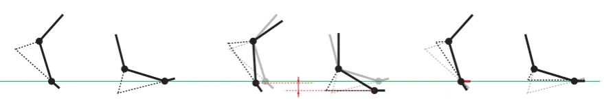
In the case of locomotion, the footstep cleanup (i.e., footstep constraints enforcement) is the most important step when retargeting a motion. Essentially, any constraint based motion editing method can provide a solution, but a targeted method can more successfully address this particular issue. Kovar et al. (2002b) provides such a method, combining successive steps of root displacement, a specic variant of analytic leg inverse kinematic, root trajectory smoothing and leg lengthening. Another specic footstep cleanup method was introduced by Glardon et al. (2006), who use an IK technique with constraint preferences.
To retarget motions of other types, cleaning up the foot motion is not sucient. Gleicher (1998) introduces a retargeting technique based on spacetime optimisation, which incorporates several types of user-dened constraints, e.g., parameter value range (joint limits), point in a specic position, point constrained to a region (above ground, outside an object), stable point (for footstep cleanup), point-to-point distance (holding an object) or vector orientation (heading direction).