Int. J. Communications, Network and System Sciences, 2009, 2, 845-851
doi:10.4236/ijcns.2009.29098 Published Online December 2009 (http://www.SciRP.org/journal/ijcns/).
Frequency-Domain Receivers for Rate-1 Space-Time
Block Codes
Mário Marques da Silva1,2,3, Rui Dinis1,4, Américo M. C. Correia1,5
1
Instituto de Telecomunicações,Lisbon, Portugal
2
Centro de Estudos de Sistemas de Informação e Tecnologias Informáticas, Portugal 3
Universidade Autónoma de Lisboa, Lisboa, Portugal 4
Universidade Nova, Lisboa, Portugal 5
Instituto Superior de Ciências do Trabalho e da Empresa,Instituto Universidade de Lisboa, Lisboa, Portugal
E-mail: [email protected], [email protected], [email protected]
Received September 24, 2009; revised October 28, 2009; accepted November 30, 2009
Abstract
This paper considers iterative frequency-domain receivers for block transmission techniques with rate-1 Space Time Block Coding (STBC) for two and four transmit antennas using both Orthogonal Frequency Di-vision Multiplexing (OFDM) and Single-Carrier (SC) schemes. The proposed receiver includes an interfer-ence canceller which enhances the performance of the non-orthogonal STBC scheme with 4 transmit anten-nas, allowing performances close to those of orthogonal codes. Our performance results show that combining STBC with block transmission techniques allows excellent performances.
Keywords:SC-FDE, Turbo Equalization, STBC, OFDM
1. Introduction
Block transmission techniques, with appropriate cyclic prefixes and employing FDE techniques (Frequency- Domain Equalization), have been shown to be suitable for high data rate transmission over severely time-dis-persive channels [1,2]. OFDM (Orthogonal Frequency Division Multiplexing) is the most popular modulation based on this technique.
Single Carrier modulation using FDE is an alternative approach based on this principle. As with OFDM, the data blocks are preceded by a cyclic prefix, long enough to cope with the overall channel length. Due to the lower envelope fluctuations of the transmitted signals, and im-plicitly a lower PMEPR (Peak-to-Mean Envelope Power Ratio), Single Carrier – Frequency Domain Equalization (SC-FDE) schemes (also named as Single Carrier-Fre- quency Domain Multiple Access (SC-FDMA) are espe-cially interesting for the uplink transmission (i.e., the transmission from the mobile terminal to the base station) [1,2].
OFDM transmission technique has been selected for the downlink of Long Term Evolution (LTE) in Release 8 of Third Generation Partnership Project (3GPP), as opposed to WCDMA which is the air interface technique that has been selected by European Telecommunications Standard Institute (ETSI) for UMTS. Moreover, SC-FDE
technique has been selected for the uplink of LTE in Re-lease 8 of 3GPP, to be deployed in 2010.
A promising Iterative Block–Decision Feedback Equalization technique (IB-DFE) for SC-FDE was pro-posed in [3] and extended to other scenarios in [4] and [5]. These IB-DFE receivers can be regarded as iterative DFE receivers where the feedforward and the feedback operations are implemented in the frequency domain, enhancing the performance as compared to non-iterative methods [3–5].
Transmit Diversity (TD) techniques are particularly interesting for fading channels where it is difficult to have multiple receive antennas (as in conventional re-ceiver diversity schemes). A possible scenario is the downlink transmission where the base station uses sev-eral transmittal antennas and the mobile terminal has a single one [6,7].
The application of Alamouti like transmit diversity in OFDM schemes is more-or-less straightforward [8]. With respect to SC-FDE schemes, [9] proposed a way of combining it with a linear FDE. This technique was ex-tended to SC-FDE with IB-DFE in [10].
diversity. For OFDM schemes we consider conventional receiver and for SC-FDE schemes we consider IB-DFE receivers. For non-orthogonal codes (i.e., with more than two transmit antennas), we also consider iterative re-ceivers with cancellation of the residual interference (for SC schemes with IB-DFE receivers, this means a negli-gible increase on the receiver complexity).
This paper is organized as follows. The system con-sidered in this paper is introduced in Section 2 and Sec-tion 3 describes the proposed iterative receiver structure for SC-FDE systems with transmit diversity. A set of performance results is presented in Section 4 and Section 5 contains the conclusions of this paper.
2. System Characterization
2.1. Space Time Block Coding for Two Antennas
We consider block transmission schemes and the lth
transmitted block has the form
1 ,
G N
l n l T S
n N
s t s h t nT
(1)with Ts denoting the symbol duration, NG denoting the number of samples at the cyclic prefix and hT(t) is the adopted pulse shaping filter. For a single transmit an-tenna system, the signal Sl(t) is transmitted over a time-dispersive channel and the signal at the receiver input is sampled and the cyclic prefix is removed, lead-ing to the time-domain block
yn l,;n0,1,...,N1
,which is then subject to the frequency domain equaliza-tion. For SC-FDE schemes the lth time-domain block to
be transmitted is
sn l,;n0,1,...,N1
, where Sn, l is the nth data symbol, selected from a given constellation (e.g.,a QPSK constellation) under an appropriate mapping rule (it is assumed that sn l, sN n l , , n NG,NG1,..., 1 ); the frequency-domain blocks associated with the data are
Sk l,;k0,1,...,N 1
DFT s
n l,;n0,1,...,N1
. For OFDM schemes, the data symbols are transmitted in the fre-quency domain, i.e., Sk, l are selected according to an appropriate constellation. At the output of the FDE wehave the samples *
2
, , , ,
k l k l k l k l
A Y H H . In the OFDM case this equalization process is simply accom-plished through *
, , ,
k l k l k l
A Y H .
If we employ Alamouti’s transmit diversity we need some processing at the transmitter. The Alamouti’s cod-ing can be implemented either in the time domain or in the frequency domain. In this paper we consider time- domain coding, although the extension to frequency do-main coding is straightforward. By considering the Space Time Block Coding with two transmit antennas, the time-domain blocks to be transmitted by the mth antenna
(m = 1 or 2) are
, ; 0,1,..., 1
m n l
s n N , with
1
,2 1 ,2 1
2 *
,2 1 ,2
1
,2 ,2
2 *
,2 ,2 1
n l n l
n l n l
n l n l
n l n l
s a
s a
s a
s a
(2)
Considering the matrix-vector representation, this is equivalent to
,1 ,2
, 1,2 * *
,2 ,1
n n
n
n n
a a
a a
A (3)
Assuming that the cyclic prefix is longer than the overall channel impulse response of each channel, the lth
frequency-domain block after the FDE block (i.e., the DFT of the lth received time-domain block, after
remov-ing the cyclic prefix) is
yn l,;n0,1,...,N 1
IDFT Y
k l,;k0,1,...,N1
, with 1 1 2 2
, , , , , ,
k l k l k l k l k l k l
Y S H S H N (4)
where
, ; 0,1,..., 1 , ; 0,1,..., 1
m m
k l n l
H k N DFT h n N denotes the channel frequency response for the kth
sub-carrier and the mth transmit antenna (the channel is
as-sumed invariant in the frame) and Nk, l is the fre-quency-domain block channel noise for that subcarrier and the lth block. Assuming, for now, the conventional
linear FDE for SC schemes, the Alamouti’s post-proc-essing for two antennas (denoted in this paper STBC2) comes,
1 * * 2 (2)
,2 1 ,2 1 , ,2 ,
1 * * 2 (2)
,2 ,2 , ,2 1 ,
k l k l k l k l k l k
k l k l k l k l k l k
A Y H Y H
A Y H Y H
(5)
where
Ak m, ,k 0,1...,N
DFT a
n m, ,n0,1...,N
andwhere ( 2 ) 1 2 2 2 1
, ,
k Hk l Hk l
. This leads to
2 (2)
,2 ,2 , ,2
1
0,1
M
m eq
k l j k l j k l k k l j m
A A H N j
. In addition,
we define ENk l, 2/ESk,2lj2. ,
eq k l
N denotes the
equivalent noise for detection purposes, with
2
2 2 ( 2 )
, ,
1
2 M m
e q
k l N k l k
m
E N H
, and with2 2
, 2
N E Nk l
.
The Alamouti’s post-processing for OFDM signals is the same as defined in (5) but without multiplying by the
(2)
k
2.2. Space Time Block Coding for Four Antennas
Using unspecified complex valued modulation, such an improvement is possible only for the two antenna scheme. Higher schemes with 4 and 8 antennas with code rate one exists only in the case of binary transmis-sion [13]. The proposed STBC4 scheme has M=4
trans-mit antennas, presenting a code rate one. The symbol construction can be generally written as [11–12]
*
, 1,2 , 3,4
, 1,4 *
, 3,4 , 1,2
n n n n n A A A
A A (6)
whereAn, 3,4 is the same asAn, 1,2 , by replacing the
sub-scripts 1 by 3 and 2 by 4. Similarly to (2), considering the Space Time Block Coding with four transmit anten-nas, the time-domain blocks to be transmitted by the mth
antenna (m = 1, 2, 3 or 4) are
, ; 0,1,..., 1
m n l
s n N , with
1 1 1 1
,4 3 ,4 3 ,4 2 ,4 2 ,4 1 ,4 1 ,4
2 * 2 * 2 *
,4 3 ,4 2 ,4 2 ,4 3 ,4 1 ,4
3 * 3 * 3 *
,4 3 ,4 1 ,4 2 ,4 ,4 1 ,4 3
4 4 4
,4 3 ,4 ,4 2 ,4 1 ,4 1 ,4
n l n l n l n l n l n l n l
n l n l n l n l n l n l
n l n l n l n l n l n l
n l n l n l n l n l n l
s a s a s a s
s a s a s a
s a s a s a
s a s a s a
,4 2 *
,4 ,4 1
3 *
,4 ,4 2
4
,4 ,4 3
n l
n l n l
n l n l
n l n l a s a s a s a (7) The lth frequency-domain block after the FDE block
(i.e., the DFT of the lth received time-domain block,
af-ter removing the cyclic prefix) is
yn l,;n0,1,...,N 1
k l,; 0,1,..., 1
IDFT Y k N , with
1 1 2 2 3 3 4 4
, , , , , , , , , ,
k l k l k l k l k l k l k l k l k l k l
Y S H S H S H S H N (8)
Assuming, for now, the conventional SC-FDE decod-ing (i.e., no IB-DFE receiver), the post-processdecod-ing STBC for four antennas (M=4) comes,
1 * * 2 * 3 4 * (4)
,4 3 ,4 3 , ,4 2 , ,4 1 , ,4 ,
Re 2
,4 3 , ,4 ,4 3
1
1 * * 2 * 3
,4 2 ,4 2 , ,4 3 , ,4 ,
k l k l k l k l k l k l k l k l k l k Desired Symbol
sidual Interference M
m eq
k l k l k k l k l
m
k l k l k l k l k l k l k l
A Y H Y H Y H Y H
A H C A N
A Y H Y H Y H
4 * (4) ,4 1 ,
2
,4 2 , ,4 1 ,4 2
1
1 * * 2 * 3 4 * (4)
,4 1 ,4 1 , ,4 , ,4 3 , ,4 2 ,
2
,4 1 , ,4 2 ,4 1
1 1 *
,4 ,4 , ,4 1
k l k l k M
m eq
k l k l k k l k l m
k l k l k l k l k l k l k l k l k l k M
m eq
k l k l k k l k l m
k l k l k l k l
Y H
A H C A N
A Y H Y H Y H Y H
A H C A N
A Y H Y
2 3 4 *
* * (4)
, ,4 2 , ,4 3 ,
2
,4 , ,4 3 ,4
1
k l k l k l k l k l k M
m eq
k l k l k k l k l m
H Y H Y H
A H C A N
(9)with
1 2 ( 4) , 1 M m
k k l
m H
, where is defined asabove (j=1,2,3,4), and where Ck2Re
H Hk l 1 *, k l4, H Hk l ,2 k l3 *,
2 , 1 M m k l m H
which stands for the residual interferencecoefficient generated in the STBC decoding process. In the following we will show how we can remove this re-sidual interference.
3. Receiver Design
In this section we describe an IB-DFE receiver for Space Time Block Coding with four antennas considering SC-FDE signals. The frequency-domain block at the output of the receiver is
,4 ; 0,1,..., 1
i k l j
A k N , with
4
1 * 2 * 3 4
,4 3 ,4 3 , ,4 2 , ,4 1 , ,4 ,
e
1
,4 , ,4 3
STBC decoding plus IB DFE feedforward
i i i i i
k l k l k l k l k l k l k l k l k l Cancellation of r sidual interference IB DFE feedback
i i i
k k l k l k l
A Y F Y F Y F Y F
C A B A
1 * 2 * 3 4
,4 2 ,4 2 , ,4 3 , ,4 , ,4 1 ,
1
,4 1 , ,4 2
1 * 2 * 3 4
,4 1 ,4 1 , ,4 , ,4 3 , ,4 2 ,
1
,4 2 , ,4 1
,4
i i i i i
k l k l k l k l k l k l k l k l k l
i i i
k k l k l k l
i i i i i
k l k l k l k l k l k l k l k l k l
i i i
k k l k l k l i
k l
A Y F Y F Y F Y F
C A B A
A Y F Y F Y F Y F
C A B A
A Y
1 * 2 * 3 4
,4 , ,4 1 , ,4 2 , ,4 3 ,
1
,4 3 , ,4
i i i i
k l k l k l k l k l k l k l k l
i i i
k k l k l k l
F Y F Y F Y F
C A B A
(10) where CK is as defined for (9). The feedforward coeffi-cients are
, ; 0,1,..., 1; 1,2,...,
i m k l
F k N m M and the
feedback coefficients are
,; 0,1,..., 1
i k l
B k N . The
block
1
1
,4 ; 0,1,..., 1 ,4 ; 0,1,..., 1
i i
n l j n l j
A n N DFT a n N
, and
denotes the DFT transform of the data estimates associated to the previous iteration, i.e., the Hard Decisions associated to the time-domain block at the
output of
1
1
,4 ; 0,1,..., 1 ,4 ; 0,1,..., 1
i i
n l j k l j
a n N IDFT A k N .
1
,4 ; 0,1,..., 1; 0,1,2,3
i k l j
A k N j denotes the average signal conditioned to the FDE output for the previous iteration
1
,4 ; 0,1,..., 1
i n l j
a n N from (19). It is worth noting that since ,4
i k l j
A presents residual interference,
the detection of ,4
i k l j
A should be accompanied by the
detection of ,4
i k l p
A (with p=3-j) to allow the
decoding process.
In case of a SISO system, (10) takes the form
1
, , , , ,
i i i i
k l k l k l k l k l
A Y F B A , i.e., there is a single branch (there
is no STBC4 decoding) and there is no cancellation of the residual interference. In case of STBC2 (two transmit antennas), there is no residual interference component.
To further improve performance with STBC4 the re-sidual interference to be subtracted (which is a function of the estimate of the symbol that generates interference), we consider an Iterative Interference Cancellation (IIC) that can be implemented as follows:
1) Compute ,4
i q k l j
A
using (10) without cancelling the residual interference.
2) Based on ,4
i q k l j
A
from i., compute ,4
i q k l p
A
after cancelling the corresponding residual interference.
3) Based on ,4
i q k l p
A
from ii., compute 1 ,4
i q k l j
A
after
cancelling the residual interference ( ,4
i k k l p
C A
).
4) Repeat steps ii. and iii. iteratively to improve the accuracy of ,4
i k l p
A
(cancellation of the residual interfer-ence), which will finally be used to improve the accuracy of ,4
i k l j
A
.
It can be shown that the optimum feedback coeffi-cients are described by [3–4].
It can be shown that the optimum feedback coeffi-cients are described by [3–4].
, , ,
1
1
M
i i m m
k l k l k l m
B F H
(11)and the feedforward coefficients are given by
,
, 2 2
1
, 1
1
m
i m k l
k l M
i m i
l k l l
m Q F H
(12)with *
, ,
m m
k l k l
Q H for m=1 or 4 and , ,
m m
k l k l
Q H for m=2
or 3. In the particular case of SISO we only have m=1
(with M=1) and Qk l, Hk l*, . In case of STBC of order
two (i.e., STBC2), we have *
, ,
m m
k l k l
Q H for m=1 and
, ,
m m
k l k l
Q H for m=2. The parameter i l
is defined as
1
, ,
1 0
1 M N
i i m m
l k l k l
m k
F H
N
(13)and the correlation factor 1 4
i l j
is defined as
1 * ,4 ,4 1 4 2 ,4 ˆi
n l j n l j i
l j
n l j
E a a
E a (14)
It can be shown that, for the QPSK modulation, the
correlation coefficient is given by [14]
1
4 ,4 ,4
0
1 2
N
i I i Q i
l j n l j n l j n
N
(15)( 4
i l j
is almost independent of l for large values of N,
provided that ,
m k l
H is constant for the frame duration),
as ,4 ,4 tanh 2 tanh 2 I i
I i n
n l j
Q i
Q i n
n l j
L L (16)
The LLRs (Log Likelihood Ratios) of the ”in-phase bit” and the ”quadrature bit”, associated to ,4
I i n l j
a and
,4
Q i n l j
a , respectively, are given by
,4 2 ,4 2 2 2
I i I i n n l j
i Q i Q i
n n l j
i L a L a (17) respectively, with
2 1 2 2
,4 ,4 ,4 ,4 ,4
0
1 1 ˆ
2 2
N
i i i
i l j n l j n l j n l j n l j n
E a a a a
N
(18)(as with 4
i l j
, i2,4lj is almost independent of l for
large values of N, provided that ,
m k l
H remains constant
for the frame duration).
The conditional average values associated with the data symbols are given by
,4 ,4
,4 tanh tanh
2 2
I i Q i
n l j n l j
i n l j
L L
a j
(19)
Therefore, the several symbols of order jth (j=0,1,2,3)
that comprise the STBC4 block need to be decoded in-dependently by the IB-DFE receiver, with the exception of the symbol estimates that originate the residual inter-ference generated in the STBC4 decoding process, as shown in (10). The IB-DFE with soft decisions described
above does not need to perform the channel decoding in the feedback loop. As an alternative, we can define a
Turbo FDE that employs the channel decoder outputs,
instead of the uncoded “soft decisions” in the feedback loop of the IB-DFE. The main difference between
IB-DFE with soft decisions and the Turbo FDE is in the
for the Turbo FDE a Soft-In, Soft-Out channel decoder is
employed in the feedback loop. The Soft-In, Soft-Out block, that can be implemented as defined in [15], pro-vides the LLRs of both the “information bits” and the ”coded bits”. The input of the Soft-In, Soft-Out block are LLRs of the ”coded bits” at the FDE output, given by (17) and (18).
The receiver for OFDM schemes with STBC2 is straightforward. For OFDM schemes with STBC4, (10) also applies with the difference that there is no feedback component, and the feedforward component only have the numerator of (12). It is worth noting that these STBC schemes can easily be extended to multiple receive an-tennas.
4. Performance Results
In this section we present a set of performance results concerning the proposed receivers, for both SC-FDE and OFDM schemes with two and four-antenna STBC schemes. We consider both Bit Error Rate (BER) and Block Error Rate (BLER) performances, which are ex-pressed as a function of Eb/ N0, where N0 is the one-sided power spectral density of the noise and Eb is the energy of the transmitted bits (i.e., the degradation due to the useless power spent on the cyclic prefix is not included).
Each block has N = 256 symbols selected from a
QPSK constellation under a Gray mapping rule (similar results were observed for other values of N, provided that N >> 1). The pulse shaping filter is raised cosine with
roll-off 0.1. The results shown in this paper considers the Pedestrian A propagation environment [16].
The channel is assumed to be invariant during the block. The duration of the useful part of the blocks (N
symbols) is 1μs and the cyclic prefix has duration 0.125μs. For SC-FDE systems we considered the IB-
DFE receiver with soft decisions and the Turbo FDE,
both with five iterations. Beyond this number the per-formance improvement was almost negligible.
Linear power amplification is considered at the trans-mitter and perfect synchronization is assumed at the re-ceiver. The channel encoder is a convolutional code with generators 1+D2+D3+D5+D6 and 1+D+D2+D3+D6, and
the coded bits associated to a given block are interleaved and mapped into the constellation points.
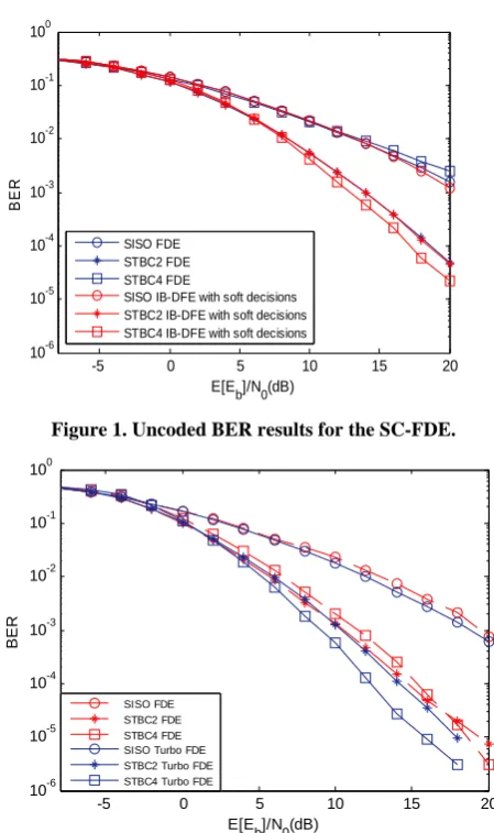
Figure 1 considers uncoded BER results for the SC- FDE and a linear FDE receiver (i.e., just the first itera-tion of the IB-DFE receiver) versus the IB-DFE receiver with soft decisions (i.e., without channel decoding in the feedback loop), in this case with five iterations. Clearly, the increased diversity due to STBC schemes leads to significant performance improvements relatively to the SISO case. From this figure, it is also clear that the IB-DFE performs always better than the linear FDE re-ceiver. It can also be observed that the STBC4 with the
[image:5.595.308.533.322.701.2]linear FDE receiver performs very badly, due to the re-sidual interference (generated in the STBC4 decoding process). However, when we add the IB-DFE with soft decisions to the STBC4, we have a significant perform-ance improvement, namely due to the ability to mitigate the residual interference. It is worth noting that, with the IB-DFE receiver, the STBC4 achieves a performance improvement over the STBC2. It happens because the proposed receiver cancels the interference generated in the STBC4 decoding process. This residual interference is, in fact, the reason why this STBC4 scheme is considered as non-orthogonal. In this case, we have seen that the non-orthogonality is not a reason for loss of perform-ance.
Figure 2 concerns the coded results for the SC-FDE. In this case, the Linear FDE and the Turbo FDE receiv-eris considered. For the linear FDE receiver, the STBC4 performs worse than the STBC2, due to the residual in-terference. However, for the Turbo FDE (i.e., the pro- posed iterative frequency-domain receiver that employs the channel decoder outputs), the STBC4 outperforms
-5 0 5 10 15 20
10-6 10-5 10-4 10-3 10-2 10-1 100
E[Eb]/N0(dB)
BE
R
SISO FDE STBC2 FDE STBC4 FDE
SISO IB-DFE with soft decisions STBC2 IB-DFE with soft decisions STBC4 IB-DFE with soft decisions
Figure 1. Uncoded BER results for the SC-FDE.
-5 0 5 10 15 20
10-6 10-5 10-4 10-3 10-2 10-1 100
E[E
b]/N0(dB)
BE
R
SISO FDE STBC2 FDE STBC4 FDE SISO Turbo FDE STBC2 Turbo FDE STBC4 Turbo FDE
[image:5.595.311.517.333.501.2]-5 0 5 10 15 20 10-6
10-5 10-4 10-3 10-2 10-1 100
E[Eb]/N0(dB)
BER
SISO Turbo FDE STBC2 Turbo FDE
STBC4 Turbo FDE (w/ residual interf cancel) SISO OFDM
STBC2 OFDM
[image:6.595.64.282.69.253.2]STBC4 OFDM (w/ residual interf cancel)
Figure 3. Coded BER for SC-FDE and OFDM.
the STBC2 (and the SISO, as expected). This is a conse-quence of the additional diversity order and the effective residual interference cancellation inherent to the pro-posed receiver. Therefore, although using a higher num-ber of antennas leads to an increase in the system com-plexity, its advantage is clear as long as the proposed iterative receiver is adopted.
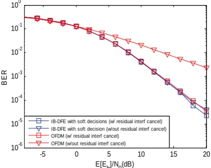
[image:6.595.319.529.313.480.2]Figure 3 shows a performance comparison between SC-FDE and OFDM when channel coding is considered (it is well-know that uncoded performances are very poor for OFDM schemes). Note that the OFDM receiver for the STBC4 also includes a residual interference canceller, similar to the one included and described in the IB-DFE that was considered for the SC-FDE STBC4. The pro-posed Turbo FDE receiver for SC-FDE signals allows similar or better performance than coded OFDM signals for the STBC schemes considered. However, OFDM technique presents much more demanding requirements in terms of PMEPR, as compared to SC-FDE technique. Figure 4 shows the uncoded BER performance of STBC4 with and without residual interference cancella-tion for both SC-FDE (in this case the IB-DFE receiver is considered) and OFDM. From this figure it is seen that, when the residual interference cancellation is considered, SC-FDE with the proposed iterative receiver achieves better results than those achieved with OFDM. Moreover, when we focus on the results without the residual inter-ference cancellation, it is clear the much better results achieved with the SC-FDE due to the inherent ability of the iterative frequency domain SC-FDE receiver to can-cel generic interference. In this case, SC-FDE without the residual interference cancellation achieves approxi-mately the same performance than that achieved with the OFDM scheme with the interference cancelled. Finally, it is noticeable the very bad performance obtained with the OFDM technique when the residual interference is not cancelled.
Figure 5 shows the coded BER performance of STBC4 with and without residual interference
cancella-tion for both SC-FDE and OFDM. From this figure it is observed that, when the residual interference cancellation is considered, SC-FDE with the proposed iterative re-ceiver (i.e., the Turbo FDE rere-ceiver) achieves similar results to those achieved with OFDM. However, when we focus on the results without the residual interference cancellation, as before, it is clear the better results achieved with the SC-FDE, for higher values of Eb/N0,
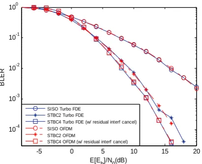
due to the inherent ability of the iterative frequency domain receiver (Turbo FDE) to cancel generic interference. Figure 6 presents results similar to Figure 3, but in terms of BLER, instead of the BER. As before, for the same di-versity order, SC-FDE schemes achieve similar results as those obtained with the OFDM. The BLER results confirm the advantage of the STBC4 over lower diversity orders.
5. Conclusions
In this paper we considered iterative frequency-do main
-5 0 5 10 15 20
10-6 10-5 10-4 10-3 10-2 10-1 100
E[Eb]/N0(dB)
BER
IB-DFE with soft decisions (w/ residual interf cancel) IB-DFE with soft decision (w/out residual interf cancel) OFDM (w/ residual interf cancel)
[image:6.595.317.529.521.692.2]OFDM (w/out residual interf cancel)
Figure 4. Uncoded BER performance for STBC4 (w/ and w/out residual interference cancellation).
-5 0 5 10 15 20
10-6 10-5 10-4 10-3 10-2 10-1 100
E[Eb]/N0(dB)
BE
R
OFDM (w/ residual interf cancel) OFDM (w/out residual interf cancel) Turbo FDE (w/ residual interf cancel) Turbo FDE (w/out residual interf cancel)
-5 0 5 10 15 20 10-4
10-3 10-2 10-1 100
E[Eb]/N0(dB)
BL
ER
SISO Turbo FDE STBC2 Turbo FDE
STBC4 Turbo FDE (w/ residual interf cancel) SISO OFDM
STBC2 OFDM
[image:7.595.70.276.77.244.2]STBC4 OFDM (w/ residual interf cancel)
Figure 6. Coded BLER for SC-FDE and OFDM
receivers for SC-FDE technique with code rate-1 STBC using two or four transmit antennas. OFDM technique was also considered in system description and perform-ance results.
Since our STBC with 4 transmit antennas is not or-thogonal, our receiver includes the cancellation of the residual interference.
The proposed Turbo FDE receiver for SC-FDE signals allows similar or better performance than coded OFDM signals with the same diversity order. However, OFDM technique presents much more demanding requirements in terms of PMEPR, as compared to SC-FDE technique, limiting its applicability. In this sense, SC-FDE is a good alternative to OFDM transmission technique, especially for the uplink.
It was shown that the best overall performance is achieved with STBC4 schemes, as long as the receiver includes the described residual interference cancellation system. It is worth noting that by adding N order receive
diversity (N receive antennas instead of a single one), the
proposed SC-FDE STBC4 receiver keeps being valid and the system can be seen as a 4×N MIMO system.
6. Acknowledgements
This work was supported by the Portuguese Foundation for the Science and Technology (FCT).
7. References
[1] A. Gusmão, R. Dinis, J. Conceicão, and N. Esteves, “Comparison of two modulation choices for broadband wireless communications,” Proceedings IEEE VTC Spring, pp. 1300–1305, May 2000.
[2] D. Falconer, S. Ariyavisitakul, A. Benyamin-Seeyar, and
B. Eidson, ”Frequency domain equalization for single- carrier broadband wireless systems,” IEEE Communica-tions Magazines, Vol. 4, No. 4, pp. 58–66, April 2002. [3] N. Benvenuto and S. Tomasin, “Block iterative DFE for
single carrier modulation,” IEE Electronic Letters, Vol. 39, No. 19, September 2002.
[4] R. Dinis, A. Gusmão, and N. Esteves, “On broadband block transmission over strongly frequency-selective fad-ing channels,” Wireless 2003, Calgary, Canada, July 2003. [5] R. Dinis, R. Kalbasi, D. Falconer, and A. Banihashemi,
“Iterative layered space-time receivers for single-carrier transmission over severe time-dispersive channels,” IEEE Communication Letters, Vol. 8, No. 9, pp. 579–581, September 2004.
[6] S. M. Alamouti, “A simple transmitter diversity scheme for wireless communications,” IEEE JSAC, pp. 1451– 1458, October 1998.
[7] Tarokh, et al., “Space-time block codes from orthogonal designs,” IEEE Transactions on Information Theory, pp. 1456–1467, July 1999.
[8] J. Wang, O. Wen, S. Li, R. Shu, and K. Cheng, “Capacity of alamouti coded OFDM systems in time-varying mul-tipath rayleigh fading channels,” IEEE VTC’06 (Spring), May 2006.
[9] N. Al-Dhahir, “Single-carrier frequency-domain equali-zation for space-time block-coded transmission over fre-quency-selective fading channels,” IEEE Communica-tions Letters, Vol. 5, July 2001.
[10] R. Dinis, A. Gusmão, and N. Esteves, “Iterative block- DFE techniques for single-carrier-based broadband com- munications with transmit/receive space diversity,” IEEE ISWCS’04, Port Louis, Mauritius, September 2004. [11] M. M. Silva and A. Correia, “Space time block coding for
4 antennas with coding rate 1,” IEEE International Sym-posium on Spread Spectrum Techniques and Application (ISSSTA), Prague, Check Republic, 2–5 September 2002. [12] M. M. Silva, A. Correia, and R. Dinis, “Wireless systems on transmission techniques for multi-antenna W-CDMA systems”, European Transactions on Telecommunications, Wiley Interscience, DOI: 10.1002/ett.1252, http://dx.doi. org/10.1002/ett.1252, published on-line in advance of print in 16 November 2007.
[13] B. Hochwald, T. Marzetta, and C. Papadias, “A transmitter diversity scheme for wideband CDMA systems based on space-time spreading,” IEEE Journal on Selected Area in Communications, Vol. 19, No. 1, pp. 48–60, January 2001. [14] A. Gusmão, P. Torres, R. Dinis, and N. Esteves, “A class
of iterative FDE techniques for reduced-CP SC-based block transmission,” International Symposium on Turbo Codes, April 2006.
[15] B. Vucetic and J. Yuan, “Turbo codes: principles and applications,” Kluwer Academic Publication, 2002. [16] ETSI, “Channel models for hiperLAN/2 in different indoor