warwick.ac.uk/lib-publications
Original citation:
Wu, Zhongze, Zhu, Z. Q. and Zhan, Hanlin. (2017) Comparative analysis of partitioned stator
flux reversal PM machine and magnetically geared machine operating in Stator-PM and
Rotor-PM modes. IEEE Transactions on Energy Conversion.
Permanent WRAP URL:
http://wrap.warwick.ac.uk/88897
Copyright and reuse:
The Warwick Research Archive Portal (WRAP) makes this work by researchers of the
University of Warwick available open access under the following conditions. Copyright ©
and all moral rights to the version of the paper presented here belong to the individual
author(s) and/or other copyright owners. To the extent reasonable and practicable the
material made available in WRAP has been checked for eligibility before being made
available.
Copies of full items can be used for personal research or study, educational, or not-for profit
purposes without prior permission or charge. Provided that the authors, title and full
bibliographic details are credited, a hyperlink and/or URL is given for the original metadata
page and the content is not changed in any way.
Publisher’s statement:
“© 2017 IEEE. Personal use of this material is permitted. Permission from IEEE must be
obtained for all other uses, in any current or future media, including reprinting
/republishing this material for advertising or promotional purposes, creating new collective
works, for resale or redistribution to servers or lists, or reuse of any copyrighted component
of this work in other works.”
A note on versions:
The version presented here may differ from the published version or, version of record, if
you wish to cite this item you are advised to consult the publisher’s version. Please see the
‘permanent WRAP URL’ above for details on accessing the published version and note that
access may require a subscription.
1Abstract– In this paper, the partitioned stator flux reversal permanent magnet (PM) (PS-FRPM) machine and the conventional magnetically geared (MG) machine operating in both stator-PM (SPM) and rotor-PM (RPM) modes are comparatively analyzed in terms of electromagnetic performance to provide design guides for a MG machine regarding: (a) a SPM or RPM type machine and (b) a higher or lower gear ratio machine. It is found that a SPM type machine is recommended, since both PS-FRPM and MG machines operating in SPM modes have a higher phase back-EMF and hence torque than their RPM counterparts, respectively, as a result of a similar phase flux-linkage but a higher electric frequency since the iron piece number is larger than the PM pole-pair number. Moreover, a smaller gear ratio machine is preferred from the perspective of a higher power factor and hence a lower inverter power rating, as the conventional MG machines with higher gear ratios suffer from larger flux-leakage, higher synchronous reactance and hence lower power factors, as well as higher iron losses, than the PS-FRPM machines. However, higher gear ratio machines feature lower cogging torques and torque ripples due to the smaller difference between the PM pole-pair number and iron piece number. Both prototypes of PS-FRPM machine operating in SPM mode and MG machine operating in RPM mode are built and tested to verify the FE predicted results.
Index Terms— Flux modulated machine, flux reversal,
magnetically geared (MG) machine, partitioned stator, permanent magnet (PM), power factor, rotor-permanent magnet, stator-permanent magnet.
I. INTRODUCTION
ERMANENT MAGNET (PM) machines have been used for many applications from automotive to domestic, due to the high torque density and efficiency [1]-[5]. According to the PM locations, PM machines can be classified into two types [3], i.e. the rotor-PM machines having rotating PMs [4]-[7], and the stator-PM machines in which PMs are static in the stator.
For the rotor-PM machines with distributed windings having less spatial armature reaction magnetomotive force (MMF) harmonics [4], the average electromagnetic torque is generated by the fundamental air-gap field. Although the spatial armature reaction MMF harmonics caused by the modulation of stator slots in the conventional rotor-PM machines having concentrated windings can produce ~5% of the electromagnetic torque [8], the accompanying parasitic effects such as rotor losses, noise, vibration, unbalanced
Zhongze Wu, Z. Q. Zhu, and Hanlin Zhan are with the Electrical Machines and Drives Group, The University of Sheffield, Sheffield,
U.K. ([email protected], [email protected],
magnetic pull, etc. are severer [9]. However, the torque component can be effectively enlarged when the modulation of stator slots is enhanced in the rotor-PM machine, which can be classified as a vernier machine [10]-[13]. As revealed in [10] and [11], the operation principle of a vernier machine is similar to a magnetic gear [14]-[17] and a magnetically geared (MG) machine [18]-[29]. The modulation of stator slots to the open-circuit PM and armature reaction fields makes them synchronous to each other, generating average electromagnetic torque.
Magnetic gear is a torque transmit device, which consists of two PM bodies and iron pieces modulating the PM MMFs [14]. Torque can be transmitted between every two parts of them, with various gear ratios being obtained [15]. However, in a magnetic gear, the torque transmission between high- and low-speed gears is conducted electromagnetically, whilst this is completed by directly contacting in a mechanical gear. Compared with a mechanical gear, gear lubrication can be exempted in a magnetic gear, and hence noise, vibration and reliability can be improved [14]. Due to the merits of magnetic gear and the electromagnetically torque transmitting, MG machines which integrate electrical machines and magnetic gears together have drawn much attention these years [18]-[29], e.g., a 12/26/22 outer stator pole / iron piece / inner PM pole-pair counterpart shown in Fig. 1, due to low speed high torque characteristic. MG machines can be potentially applied to electric vehicles (EVs) [21], hybrid electric vehicles (HEVs) [22], and wind turbines [23], [24], as well as high performance motion control applications [25]. For the magnetic gear with two rotating PM bodies whilst the iron pieces are static as analyzed in [14] and [15], the MG machine analyzed in [18] can be obtained by displacing one rotating PM body using an equivalent armature winding stator, as shown in Fig. 1.
For the other category PM machines, i.e. stator-PM machines, they also operate based on the magnetic gearing effect, similar to magnetic gears [14]-[17] and MG machines [18]-[29]. The modulation of the salient rotor to the static open-circuit PM field and the rotating armature reaction field makes them synchronous to each other in the air-gap, generating average electromagnetic torque [8]. There are three types of stator-PM machines, including doubly salient PM (DSPM) machines having yoke-inserted PMs [30], [31], switched flux PM (SFPM) machines having tooth-sandwiched PMs [32]-[39] and flux reversal PM (FRPM) machines having tooth-surface-mounted PMs [40]-[42]. Compared with the DSPM and SFPM machines, the FRPM machines have an integral stator lamination, which is better
P
Comparative Analysis of Partitioned Stator Flux
Reversal PM Machine and Magnetically Geared
Machine Operating in Stator-PM and Rotor-PM
Modes
for manufacturing.
Based on the operation principle of conventional stator-PM machines having single stator, stator-PMs and armature windings in the conventional FRPM machine are separately placed in two stators to form the partitioned stator (PS) FRPM (PS-FRPM) machine with enlarged total stator areas and hence torque density [43], e.g. 12/10-stator/rotor-pole PS-FRPM machine shown in Fig. 2. As shown in Fig. 2, the topology of the PS-FRPM machine is similar to the MG machine illustrated in Fig. 1. Indeed, the PS-FRPM machine also operate based on the modulation effect of iron pieces to open-circuit PM and armature reaction MMFs, similar to the PS-SFPM machine. The modulation of the iron pieces to the open-circuit PM and armature reaction fields makes them synchronous in the air-gaps, generating average electromagnetic torque, similar to the MG machine shown in Fig. 1. Similar to a magnetic gear, the armature reaction pole-pair number par, the iron piece number Nip and PM
pole-pair number pPM in both machines satisfy,
[image:3.595.66.286.281.428.2]𝑁𝑖𝑝= 𝑝𝑎𝑟+ 𝑝𝑃𝑀 (1)
Fig. 1. Cross-section of the MG machine having 12/26/22 outer stator pole / iron piece / inner PM pole-pair.
Fig. 2. Cross-section of the PS-FRPM machine having 12/10/6 outer stator pole / iron piece / inner PM pole-pair.
However, two major differences between the PS-FRPM machine shown in Fig. 2 and the conventional MG machine shown in Fig. 1 are,
(1) In the PS-FRPM machine shown in Fig. 2, the PMs are static whilst the iron pieces are rotating. However, the PMs are rotating in the MG machine illustrated in Fig. 1, whilst the iron pieces are static.
(2) Although both the PS-FRPM machine shown in Fig. 2 and the MG machine shown in Fig. 1 have the same outer stator pole number Nos=12, the same winding topology
and hence the armature reaction pole-pair number par=4,
[8], the iron piece number Nip and the PM pole-pair
number pPM are quite different, i.e. different gear ratios.
Similar to the conventional FRPM machines, Nos=2pPM in
the PS-FRPM machine, and Nip=Nos2 or Nip=Nos1.
However, in the conventional MG machines, Nip and pPM
are several times of par. Therefore, the gear ratio of the
conventional MG machine is higher than that of the PS-FRPM machine.
Based on the aforementioned two differences, electromagnetic performance of the conventional MG machine shown in Fig. 1, and the PS-FRPM machine shown in Fig. 2 operating in both SPM and RPM modes will be comprehensively compared in this paper, which aims to provide design guides for a MG machine regarding: (a) a SPM or RPM type machine and (b) a higher or smaller gear ratio machine.
This paper is organized as follows. In section II, the magnetic gearing effect of the conventional MG machine and the PS-FRPM machine operating in both SPM and RPM modes is introduced from the perspective of modulation effect of iron pieces to the open-circuit PM and armature reaction MMFs by a simple MMF-permeance model. This aims to show that the MG machines and the PS-FRPM machines have similar operation principle, i.e. modulation effect, via the qualitative analysis on the pole-pair numbers and rotating speeds of the air-gap field harmonics. The contribution of the main air-gaps harmonics to the average electromagnetic torque is also comparatively investigated for both the conventional MG machine and the PS-FRPM machine in section II. Quantitative and comprehensive comparison of electromagnetic performance of the MG machine and the PS-FRPM machine operating in both SPM and RPM modes is conducted by finite element (FE) analyses in section III. This aims to make recommendations for various applications according to specific requirements, such as lower back-EMF harmonics, cogging torque and torque ripple for wind turbines and motion control applications, and higher power factor for EVs and HEVs. In section IV, the MG machine operating in RPM mode is built and tested to verify the FE predicted results, comparing to the PS-FRPM machine operating in SPM mode which is built and tested in [43].
II. OPERATION PRINCIPLE
In this section, firstly the magnetic gearing effect in the conventional MG machine and the PS-FRPM machine operating in both SPM and RPM modes is introduced based on a simple MMF-permeance model. Then, the contribution of main air-gap field harmonics to the average electromagnetic torque in both PS-FRPM and MG machines is analyzed, as given as follows.
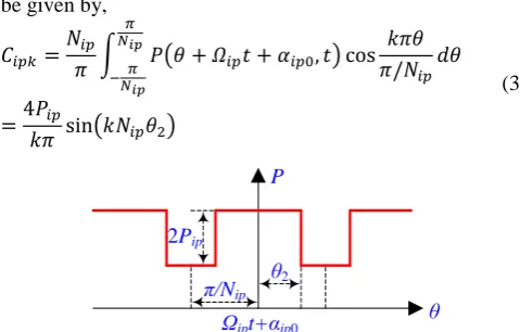
The air-gap permeance waveform accounting for slots between iron pieces is shown in Fig. 3, where 2Pip is the
peak-to-peak value of air-gap permeance waveform. Nip is
the iron piece number. θ2 is half of the rotor iron piece arc.
αip0 is the initial iron piece position. Ωip is the mechanical
angular speed of iron pieces in unit of rad/s, of which the positive direction is anticlockwise. In RPM machines, Ωip=0.
The air-gap permeance waveform can be expressed in Fourier series by,
𝑃(𝜃, 𝑡) = 𝑃0+ ∑ {𝐶𝑖𝑝𝑘cos {
𝑘𝜋[𝜃 − (𝛺𝑖𝑝𝑡 + 𝛼𝑖𝑝0)]
𝜋/𝑁𝑖𝑝
}}
∞
𝑘=1
(2)
where P0 is the DC component of air-gap permeance. Cipkis
the Fourier coefficient of the air-gap permeance, which can
Armature winding
Stator Static iron piece
PM
Rotor
Armature winding
Outer Stator Rotor iron piece PM
[image:3.595.52.284.314.585.2]be given by,
𝐶𝑖𝑝𝑘=
𝑁𝑖𝑝
𝜋 ∫ 𝑃(𝜃 + 𝛺𝑖𝑝𝑡 + 𝛼𝑖𝑝0, 𝑡) cos 𝑘𝜋𝜃 𝜋/𝑁𝑖𝑝 𝜋
𝑁𝑖𝑝 −𝑁𝜋
𝑖𝑝
𝑑𝜃
=4𝑃𝑖𝑝
𝑘𝜋 sin(𝑘𝑁𝑖𝑝𝜃2)
(3)
Fig. 3. Air-gap permeance waveform accounting for slots between iron pieces.
Based on (2) and (3), the Fourier series of the air-gap permeance waveform can be rewritten as,
{
𝑃(𝜃, 𝑡) = 𝑃0+ 𝑉𝑖𝑝∑{𝑀𝑖𝑝𝑘cos[𝑘𝑁𝑖𝑝(𝜃 − 𝛺𝑖𝑝𝑡 − 𝛼𝑖𝑝0)]} ∞
𝑘=1
𝑉𝑖𝑝=
4𝑃𝑖𝑝
𝜋
𝑀𝑖𝑝𝑘=
sin(𝑘𝑁𝑖𝑝𝜃2)
𝑘
(4)
where Vip is the constant in air-gap permeance. Mipk is the
coefficient of air-gap permeance determined by k.
The open-circuit PM MMF is shown in Fig. 4, where pPM
is the PM pole-pair number. FPMs is the PM MMF square
waveform peak value. θ1 is the half of arc between PMs. αip0
is the PM position. ΩPM is the mechanical angular speed of
PMs in unit of rad/s, of which the positive direction is clockwise. In SPM machines, ΩPM=0. The open-circuit PM
MMF waveform can be expressed in Fourier series by,
𝐹𝑃𝑀(𝜃, 𝑡) = ∑ {𝐶𝑃𝑀𝑖sin {
𝑖𝜋[𝜃 − (𝛺𝑃𝑀𝑡 + 𝛼𝑃𝑀0)]
𝜋/𝑝𝑃𝑀
}}
∞
𝑖=1
(5)
where CPMiis the Fourier coefficient of the PM MMF, which
can be given by, 𝐶𝑃𝑀𝑖
=𝑝𝑃𝑀
𝜋 ∫ 𝐹𝑃𝑀(𝜃 + 𝛺𝑃𝑀𝑡 + 𝛼𝑃𝑀0, 𝑡)
𝜋 𝑝𝑃𝑀 − 𝜋
𝑝𝑃𝑀
sin 𝑖𝜋𝜃 𝜋/𝑝𝑃𝑀
𝑑𝜃
=2𝐹𝑃𝑀𝑠
𝑖𝜋 [cos(𝑖𝑝𝑃𝑀𝜃1) − cos(𝑖𝑝𝑃𝑀𝜃1− 𝑖𝜋)]
= { 4𝐹𝑃𝑀𝑠
𝑖𝜋 cos(𝑖𝑝𝑃𝑀𝜃1) , 𝑖 = 1,3,5, … 0, 𝑖 = 2,4,6, …
(6)
Based on (5) and (6), the Fourier series of the PM MMF waveform can be rewritten as,
{
𝐹𝑃𝑀(𝜃, 𝑡) = 𝑉𝑃𝑀∑{𝑀𝑃𝑀𝑖sin[(2𝑖 − 1)𝑝𝑃𝑀(𝜃 − 𝛺𝑃𝑀𝑡 − 𝛼𝑃𝑀0)]} ∞
𝑖=1
𝑉𝑃𝑀=
4𝐹𝑃𝑀𝑠
𝜋
𝑀𝑃𝑀𝑖=
cos[(2𝑖 − 1)𝑝𝑃𝑀𝜃1]
2𝑖 − 1
(7)
where VPM is the constant in PM MMF. MPMi is the
coefficient of PM MMF waveform determined by i.
The armature reaction MMF waveform is illustrated in Fig. 5, where FA, FB, and FC are the A-, B-, and C-phase
armature reaction MMFs, respectively. Nc is the number of
coil turns. θ3 is half of outer stator tooth arc θost plus outer
stator tooth tip arc θot. iA, iB, and iC are the A-, B-, and C
-phase currents, respectively, which can be given by,
{
𝑖𝐴= √2𝐼𝑟𝑚𝑠sin(𝜔𝑒𝑡)
𝑖𝐵 = √2𝐼𝑟𝑚𝑠sin (𝜔𝑒𝑡 −
2𝜋 3) 𝑖𝐶 = √2𝐼𝑟𝑚𝑠sin (𝜔𝑒𝑡 +
2𝜋 3)
(8)
where Irms is the phase current RMS value. ωe is the rotor
electrical angular speed in rad/s.
Fig. 4. PM MMF.
The three-phase armature reaction MMF FABC can be
expressed as,
𝐹𝐴𝐵𝐶(𝜃, 𝑡) = 𝐹𝐴(𝜃, 𝑡) + 𝐹𝐵(𝜃, 𝑡) + 𝐹𝐶(𝜃, 𝑡) (9) where FA(θ,t), FB(θ,t), and FC(θ,t) can be expressed in
Fourier series by,
{
𝐹𝐴(𝜃, 𝑡) =
𝑁𝑐𝑖𝐴
2 + ∑ (𝐶𝐴𝑞cos 𝑞𝜋𝜃 𝜋/4)
∞
𝑞=1
𝐹𝐵(𝜃, 𝑡) =
𝑁𝑐𝑖𝐵
2 + ∑ {𝐶𝐵𝑞cos [
𝑞𝜋 (𝜃 +2𝜋3) 𝜋/4 ]}
∞
𝑞=1
𝐹𝐶(𝜃, 𝑡) =
𝑁𝑐𝑖𝐶
2 + ∑ {𝐶𝐶𝑞cos [
𝑞𝜋 (𝜃 −2𝜋3) 𝜋/4 ]}
∞
𝑞=1
(10)
where CAq, CBq and CCq are the Fourier coefficients of the A-,
B-, and C-phase armature reaction MMFs, respectively, which can be given by,
{ 𝐶𝐴𝑞=
4
𝜋∫ 𝐹𝐴(𝜃, 𝑡) cos 𝑞𝜋𝜃 𝜋/4
−𝜋4
−𝜋4
𝑑𝜃
𝐶𝐵𝑞=
4
𝜋∫ 𝐹𝐵(𝜃 − 2𝜋
3 , 𝑡) cos 𝑞𝜋𝜃 𝜋/4
−𝜋4
−𝜋 4
𝑑𝜃
𝐶𝐶𝑞=
4
𝜋∫ 𝐹𝐶(𝜃 + 2𝜋
3 , 𝑡) cos 𝑞𝜋𝜃 𝜋/4
−𝜋4
−𝜋4
𝑑𝜃
(11)
Based on (8) and Fig. 5, CAq, CBq and CCq shown in (11)
can be calculated as,
{ 𝐶𝐴𝑞=
2√2𝑁𝑐𝐼𝑟𝑚𝑠
𝑞𝜋 sin(4𝑞𝜃3) sin(𝜔𝑒𝑡)
𝐶𝐵𝑞 =
2√2𝑁𝑐𝐼𝑟𝑚𝑠
𝑞𝜋 sin(4𝑞𝜃3) sin (𝜔𝑒𝑡 − 2𝜋
3)
𝐶𝐶𝑞=
2√2𝑁𝑐𝐼𝑟𝑚𝑠
𝑞𝜋 sin(4𝑞𝜃3) sin (𝜔𝑒𝑡 + 2𝜋
3)
(12)
Submitting (10) and (12) into (9), the three-phase armature reaction MMF FABC can be rewritten as,
𝐹𝐴𝐵𝐶(𝜃, 𝑡) = ∑ {
2√2𝑁𝑐𝐼𝑟𝑚𝑠
𝑞𝜋 sin(4𝑞𝜃3) [(1
∞
𝑞=1
− cos8𝑞𝜋
3 ) sin(𝜔𝑒𝑡) cos(4𝑞𝜃) − √3sin8𝑞𝜋
3 cos(𝜔𝑒𝑡) sin(4𝑞𝜃)]}
(13)
The three-phase armature reaction MMF FABC written in
θ P
θ2
2Pip
π/Nip
Ωipt+αip0
θ FPM
-θ1 FPMs
π/2pPM
-π/2pPM π/pPM
-π/pPM
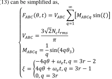
[image:4.595.45.285.52.205.2] [image:4.595.46.291.350.714.2] [image:4.595.301.552.425.771.2](13) can be simplified as,
{
𝐹𝐴𝐵𝐶(𝜃, 𝑡) = 𝑉𝐴𝐵𝐶∑[𝑀𝐴𝐵𝐶𝑞sin(𝜉)] ∞
𝑞=1
𝑉𝐴𝐵𝐶 =
3√2𝑁𝑐𝐼𝑟𝑚𝑠
𝜋 𝑀𝐴𝐵𝐶𝑞=
1
𝑞sin(4𝑞𝜃3)
𝜉 = {
−4𝑞𝜃 + 𝜔𝑒𝑡, 𝑞 = 3𝑟 − 2
4𝑞𝜃 + 𝜔𝑒𝑡, 𝑞 = 3𝑟 − 1
0, 𝑞 = 3𝑟
(14)
where VABC is a constant in armature reaction MMF. MABCq is
the coefficient of armature reaction MMF waveform determined by q. r is a positive integer mathematically.
Fig. 5. Armature reaction MMF (iA=iB=iC).
Based on (4) and (7), the air-gap open-circuit PM fields can be calculated by,
𝐵𝑃𝑀(𝜃, 𝑡) = 𝐹𝑃𝑀(𝜃, 𝑡)𝑃(𝜃, 𝑡)
= 𝑃0𝑉𝑃𝑀∑(𝑀𝑃𝑀𝑖cos 𝛼1) ∞
𝑖=1
+𝑉𝑃𝑀𝑉𝑖𝑝
2 ∑ ∑[𝑀𝑃𝑀𝑖𝑀𝑖𝑝𝑘(cos 𝛼2
∞
𝑘=1 ∞
𝑖=1
+ cos 𝛼3)]
(15)
where 𝛼j (j=1,2,3) is given by,
𝛼𝑗= 𝐻𝑗(𝜃 −
𝜔𝑗𝑡 + 𝛽𝑗
𝐻𝑗
) (16)
where Hj, ωj andβj/Hj are harmonics order, electric rotating
speed and initial phases of air-gap field harmonics. They are given by,
{
𝐻1= (2𝑖 − 1)𝑝𝑃𝑀
𝐻2= 𝑘𝑁𝑖𝑝+ (2𝑖 − 1)𝑝𝑃𝑀
𝐻3= 𝑘𝑁𝑖𝑝− (2𝑖 − 1)𝑝𝑃𝑀
(17)
and,
{
𝜔1= (2𝑖 − 1)𝑝𝑃𝑀𝛺𝑃𝑀
𝜔2= 𝑘𝑁𝑖𝑝𝛺𝑖𝑝+ (2𝑖 − 1)𝑝𝑃𝑀𝛺𝑃𝑀
𝜔3= 𝑘𝑁𝑖𝑝𝛺𝑖𝑝− (2𝑖 − 1)𝑝𝑃𝑀𝛺𝑃𝑀
(18)
and,
{
𝛽1= (2𝑖 − 1)𝑝𝑃𝑀(𝛼𝑃𝑀0+
𝜋 2) 𝛽2= 𝑘𝑁𝑖𝑝𝛼𝑖𝑝0+ (2𝑖 − 1)𝑝𝑃𝑀𝛼𝑃𝑀0+
𝜋 2 𝛽3= 𝑘𝑁𝑖𝑝𝛼𝑖𝑝0− (2𝑖 − 1)𝑝𝑃𝑀𝛼𝑃𝑀0−
𝜋 2
(19)
respectively.
Similarly, the air-gap armature reaction fields BABC(θ, t)
can be calculated from (4) and (14), as shown in (20) and (21) when q=3r-2. When q=3r-1, BABC can also be expressed
by them with the coefficient of q multiplied by ‘-1’.
𝐵𝐴𝐵𝐶(𝜃, 𝑡) = 𝐹𝐴𝐵𝐶(𝜃, 𝑡)𝑃(𝜃, 𝑡)
=3𝑃0𝑉𝐴𝐵𝐶
2 ∑ {𝑀𝐴𝐵𝐶𝑞cos [4𝑞𝜃 − 𝜔𝑒𝑡 + 𝜋 2]}
∞
𝑞=1
+3𝑉𝐴𝐵𝐶𝑉2
4 ∑ ∑[𝑀𝐴𝐵𝐶𝑞𝑀𝑖𝑝𝑘(cos 𝜎1+ cos 𝜎2)]
∞
𝑘=1 ∞
𝑞=1
(20)
where σ1 and σ2 are given as,
{
𝜎1= (𝑘𝑁𝑖𝑝− 4𝑞) [𝜃 −
(𝑘 − 1)𝜔𝑒𝑡 + 𝑘𝑁𝑖𝑝𝜃0+
𝜋 2 𝑘𝑁𝑖𝑝− 4𝑞
]
𝜎2= (𝑘𝑁𝑖𝑝+ 4𝑞) [𝜃 −
(𝑘 + 1)𝜔𝑒𝑡 + 𝑘𝑁𝑖𝑝𝜃0−𝜋2
𝑘𝑁𝑖𝑝+ 4𝑞
] (21)
(a) Outer air-gap
(b) Inner air-gap
Fig. 6. Air-gap average electromagnetic torque proportion of main harmonics.
TABLE I
CHARACTERISTICS OF AIR-GAP OPEN-CIRCUIT PMFLUX-DENSITY HARMONICS (i=1,2,3,…)
Pole-Pairs Electric Rotating Speed (rad/s)
[image:5.595.290.550.47.514.2] [image:5.595.53.512.50.753.2] [image:5.595.47.236.51.184.2](2𝑖 − 1)𝑝𝑃𝑀 (2𝑖 − 1)𝑝𝑃𝑀𝛺𝑃𝑀 𝑘𝑁𝑖𝑝+ (2𝑖 − 1)𝑝𝑃𝑀 𝑘𝑁𝑖𝑝𝛺𝑖𝑝+ (2𝑖 − 1)𝑝𝑃𝑀𝛺𝑃𝑀 |𝑘𝑁𝑖𝑝− (2𝑖 − 1)𝑝𝑃𝑀| 𝑘𝑁𝑖𝑝𝛺𝑖𝑝− (2𝑖 − 1)𝑝𝑃𝑀𝛺𝑃𝑀
TABLE II
CHARACTERISTICS OF AIR-GAP ARMATURE REACTION FLUX DENSITY HARMONICS (r=1,2,3,…)
q Pole-Pairs Electric Rotating Speed (rad/s)
3r-2
4𝑞 𝜔𝑒
4𝑞
|𝑘𝑁𝑟− 4𝑞|
𝑘 − 1 𝑘𝑁𝑟− 4𝑞
𝜔𝑒
𝑘𝑁𝑟+ 4𝑞
𝑘 + 1 𝑘𝑁𝑟+ 4𝑞
𝜔𝑒
3r-1
4𝑞 −𝜔𝑒
4𝑞
𝑘𝑁𝑟+ 4𝑞
𝑘 − 1 𝑘𝑁𝑟+ 4𝑞
𝜔𝑒
|𝑘𝑁𝑟− 4𝑞|
𝑘 + 1 𝑘𝑁𝑟− 4𝑞
𝜔𝑒
θ FA
θ FB
θ3
NCiA
NCiB
θ NCiC
-θ3
FC
-π π
-π
-π
π
π
-20
0
20
40
60
80
100 120
2 4 6 8 10 12 14 16 18 20 22 24 26 28 30 32 34 36
T
orque
proportio
n
(%
)
Harmonic order
PS-FRPM-SPM
PS-FRPM-RPM
MG-SPM
MG-RPM
-20
0
20
40
60
80
100 120
2 4 6 8 10 12 14 16 18 20 22 24 26 28 30 32 34 36
T
orque
proportio
n
(%
)
Harmonic order
PS-FRPM-SPM
PS-FRPM-RPM
MG-SPM
TABLE III
CONTRIBUTION OF MAIN AIR-GAP FIELD HARMONICS TO AVERAGE ELECTROMAGNETIC TORQUE IN PS-FRPMMACHINES (%)
Harmonic Order SPM RPM Outer Inner Outer Inner pPM 6 1.17 108.71 -9.44 99.60
Nip-pPM 4 68.03 -0.03 94.13 0.01
Nip+pPM 16 12.36 0.03 -0.29 0.31
3pPM 18 15.15 -8.71 16.55 -0.17
|Nip-3pPM| 8 -6.73 -0.01 -9.89 0.00
Nip+3pPM 28 3.44 0.01 3.63 0.07
Nos+pPM 18 - - - -
|Nos-pPM| 6 - - - -
SUM - 93.42 ~100 94.69 99.82 TABLE IV
CONTRIBUTION OF MAIN AIR-GAP FIELD HARMONICS TO AVERAGE ELECTROMAGNETIC TORQUE IN MGMACHINES (%) Harmonic Order SPM RPM
Outer Inner Outer Inner pPM 22 -6.87 99.85 -6.98 99.83
Nip-pPM 4 99.17 0.01 98.04 -0.04
Nip+pPM 48 -1.53 0.00 -1.92 0.04
3pPM 66 0.03 -0.01 0.01 0.02
|Nip-3pPM| 40 0.47 0.00 0.59 -0.00
Nip+3pPM 92 -0.03 -0.00 -0.06 -0.00
Nos+pPM 34 7.06 0.07 6.59 0.08
|Nos-pPM| 10 0.20 -0.05 0.12 -0.05
[image:6.595.317.538.281.357.2]SUM - 98.51 99.87 96.39 99.88 TABLE V
OUTER AND INNER AIR-GAP AVERAGE ELECTROMAGNETIC TORQUES (Nm) Air-gap PS-FRPM MG
SPM RPM SPM RPM Outer 1.50 1.01 0.43 0.43 Inner 1.32 1.52 2.34 2.34
Based on the foregoing analytically deduced open-circuit and armature reaction air-gap fields shown in (15) and (20), pole-pairs and electric rotating speed of the open-circuit and armature reaction air-gap fields harmonics can be listed as TABLE I and TABLE II, respectively. Since the open-circuit air-gap fields harmonics listed in TABLE I synchronous with those of armature reaction listed in TABLE II due to the modulation of iron pieces, electromagnetic torque can be generated in both outer and inner air-gaps in both PS-FRPM and MG machines, based on magnetic gearing theory [8]. This can be evidenced by FE predicted air-gap average electromagnetic torque proportion of main harmonics, as shown in Fig. 6, TABLE III and TABLE IV. In Fig. 6(a), the base torque of each machine is the outer air-gap average torque shown in TABLE V, respectively. Similarly, the base torque of each machine in Fig. 6(b) is the inner air-gap average torque shown in TABLE V, respectively.
As listed in TABLE III and TABLE IV, in all the four analyzed PS-FRPM and MG machines operating in both SPM and RPM modes, more than 93% of the average electromagnetic torque is contributed by several dominant air-gap filed harmonics, i.e. those having pole-pairs of (2i -1)pPM (i=1, 2), |kNip(2i-1)pPM| (k=1, i=1), and |Nos(2i
-1)pPM|. This is different from the conventional magnetic gear
[15], in which the average electromagnetic torque is generated by two dominant air-gap filed harmonics having pole-pairs of outer and inner PM pole-pairs. It is worth noting that the air-gap filed harmonics having pole-pairs of |Nos(2i-1)pPM| are due to the modulation of the outer stator
slots to the open-circuit PM and armature reaction MMFs, similar to vernier machines [13].
Similar to magnetic gears [15], different gear ratios can be achieved in the PS-FRPM machine and the MG machine
operating in SPM and RPM modes. For both the PS-FRPM machine and the MG machine, the gear ratios Gr can be
respectively given by,
𝐺𝑟=
𝑁𝑖𝑝
𝑝𝑎𝑟
(22)
and,
𝐺𝑟=
𝑝𝑃𝑀
𝑝𝑎𝑟 (23)
for SPM and RPM modes, respectively.
The gear ratios of the PS-FRPM machine and the MG machine operating at SPM and RPM modes are listed in TABLE VI. Generally, the conventional MG machines have higher gear ratios than the PS-FRPM machine due to the larger iron piece number and PM pole-pair number. Also, the SPM machines have slightly higher gear ratios than their RPM counterparts since the iron piece number is higher than PM pole-pair number, respectively.
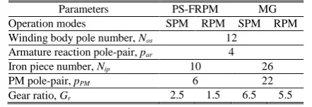
TABLE VI
GEAR RATIOS OF PS-FRPM AND MGMACHINES OPERATING IN SPM AND RPMMODES
Parameters PS-FRPM MG Operation modes SPM RPM SPM RPM Winding body pole number, Nos 12
Armature reaction pole-pair, par 4
Iron piece number, Nip 10 26
PM pole-pair, pPM 6 22
Gear ratio, Gr 2.5 1.5 6.5 5.5
III. ELECTROMAGNETIC PERFORMANCE EVALUATION
In the foregoing analysis, it is found that the PS-FRPM machine and the MG machine have the same operation principle, operating based on the modulation effect of iron pieces to the open-circuit PM and armature reaction MMFs.
In this section, the electromagnetic performance of PS-FRPM and MG machines operating in both SPM and RPM modes will be comparatively analyzed, including open-circuit flux distribution, phase flux-linkage and back-EMF, torque characteristics, loss and efficiency, inductance and power factor. Back-EMF is induced by the variation of flux-linkage, which can be integrated by the flux density along the certain path. Flux distribution can also indicate the ratio of the flux-leakage to the main flux, which is corresponding to the power factor. As well known, a low power factor will increase the power rating of the inverter. On-load torque is made up of three parts, i.e. cogging torque, PM torque due to the back-EMF and reluctance torque. Generally, average torque and efficiency are important for all the EVs, HEVs, wind generation and motion control applications. Specifically, a more sinusoidal back-EMF, a lower cogging torque and also a smoother torque are desired for wind turbines [44], as the cogging torque and pulsating torque are harmful to the starting and running of wind turbines, and the motion control applications. However, a higher power factor is also desired for machines applied to EVs and HEVs for reducing the inverter power rating due to the compact space for the inverter [1].
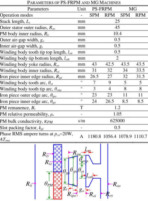
The dimensional parameters of the four analyzed machines are shown in TABLE VII, which can be referred in the linear illustration shown in Fig. 7. Since a higher average torque is commonly desired for all applications, the design parameters of the four analyzed machines are obtained by optimizing for the highest average electromagnetic torque with a fixed copper loss for a fair comparison, i.e. pcu=20W.
are fixed for each machine, whilst those from Roy to θipo are
optimized under zero d-axis current control, i.e. id=0. It
should be noted that in the optimization the PM volume is fixed as 13414.6mm3, similar to the PS-FRPM-SPM
machine in [43].
As foregoing mentioned, both a higher average torque and a larger efficiency are desired for any application. With a fixed copper loss and much smaller iron loss and PM eddy current loss, the design with a larger average torque also features a higher efficiency approximately. Therefore, by optimizing the machine for the largest average torque with a fixed copper loss, a high efficiency can also be obtained.
TABLE VII
PARAMETERS OF PS-FRPM AND MGMACHINES Parameters Unit PS-FRPM MG Operation modes - SPM RPM SPM RPM Stack length, Ls mm 25
Outer stator outer radius, Roo mm 45
PM body inner radius, Rii mm 10.4
Outer air-gap width, go mm 0.5
Inner air-gap width, gi mm 0.5
Winding body tooth tip top length, lott mm 0.5
Winding body tip bottom length, lotb mm 2
Winding body yoke radius, Roy mm 43 42.5 43.5 43.5
Winding body inner radius, Roi mm 31 32 34 33.5
Iron piece inner edge radius, Ripi mm 26.5 27 32 31.5
Winding body tooth arc, θot ° 7 9 5 5
Winding body tooth tip arc, θotip ° 3 4 8 8
Iron piece outer edge arc, θipo ° 23 23 11 11
Iron piece inner edge arc, θipi ° 24 26.5 8.5 8.5
PM remanence, Br T 1.2
PM relative permeability, μr - 1.05
PM bulk conductivity, κPM s/m 625000 Slot packing factor, kpf - 0.5
Phase RMS ampere turns at pcu=20W,
[image:7.595.304.552.49.311.2]ATrms A 1180.8 1056.4 1078.9 1110.7
Fig. 7. Illustration of design parameters in PS-FRPM and MG machines.
The reason why pcu=20W is selected as a reference for a
fair comparison of the four analyzed machines in this paper is explained as follows. As well known, the same thermal condition is usually required for a fair comparison in different machines. When the mechanical loss is neglected, the copper loss, iron loss, and PM eddy current loss are the main thermal sources. Due to the low rotor speed, the copper loss is much higher than both the iron loss and the PM eddy current loss, as will be shown later. Therefore, the same copper loss is applied in the comparison since the PS-FRPM and MG machines having similar topology, similar operation principle, and also same outer radius and stack length. The value of the copper loss 20W is determined to make sure a machine having stack length Ls=25mm and outer radius
Ro=45mm of which the average electromagnetic torque
Tavg=2Nm has an efficiency over 80% at 400rpm. However,
a higher copper loss will make challenges to the thermal dissipation.
(a) PS-FRPM-SPM (b) PS-FRPM-RPM
(c) MG-SPM (d) MG-RPM
Fig. 8. Open-circuit flux distributions at d-axis rotor position (-7mWb/m ~ 7mWb/m).
Fig. 9. Open-circuit phase A flux-linkage waveforms (coil number turns Nc=1).
A. Open-Circuit Flux-Linkage, Back-EMF, and cogging torque
Fig. 8 illustrates the open-circuit flux distribution at d -axis rotor position. Compared with the PS-FRPM machines, the MG machines suffer from more severe flux-leakage between iron pieces and PMs, which do not cross armature teeth. This is due to the higher gear ratios with higher iron piece number or PM pole-pair number. As a consequence, the MG-SPM and MG-RPM machines have lower phase flux-linkages, as shown in Fig. 9.
(a) Waveforms
Rii
gi
θipi
go
θot
Roo
Roy
Roi
Ripo
Ripi
lott
θipo
lotb
Rio
θPM
Riy
θotip
-0.6
-0.4
-0.2
0.0 0.2 0.4 0.6
0 60 120 180 240 300 360
Fl
ux
-l
in
kage
(m
W
b
)
Rotor position (elec. deg.)
PS-FRPM-SPM
PS-FRPM-RPM MG-SPM MG-RPM
-300
-200
-100 0
100
200 300
0 60 120 180 240 300 360
B
a
c
k
-E
M
F
(m
V
)
Rotor position (elec. deg.)
PS-FRPM-SPM A PS-FRPM-SPM B
PS-FRPM-SPM C PS-FRPM-RPM A
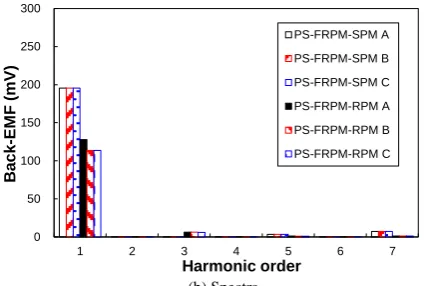
[image:7.595.45.291.196.529.2] [image:7.595.315.529.624.762.2](b) Spectra
Fig. 10. Open-circuit phase back-EMFs in the FRPM-SPM and PS-FRPM-RPM machines (Nc=1, 400rpm).
(a) Waveforms
(b) Spectra
Fig. 11. Open-circuit phase back-EMFs in the MG-SPM and MG-RPM machines (Nc=1, 400rpm).
However, due to higher gear ratios with higher iron piece number or PM pole-pair number, the SPM and MG-RPM machines exhibit larger fundamental phase back-EMFs than the PS-FRPM-SPM and PS-FRPM-RPM machines, respectively, as shown in Fig. 10 and Fig. 11. More importantly, it can be observed that the PS-FRPM-SPM machine has larger fundamental phase back-EMF than the PS-FRPM-RPM machine, although the flux-linkage of the PS-FRPM-SPM machine is even lower. This is due to that the 66.67% higher electric frequency in the PS-FRPM-SPM machine than the PS-FRPM-RPM machine, as Nip>pPM.
Similar trend can be observed between the MG-SPM and MG-RPM machines. However, the electric frequency in the MG-SPM machine is only 18.2% higher than the MG-RPM machine.
(a) Waveforms
[image:8.595.308.541.47.454.2](b) Spectra Fig. 12. Cogging torque.
TABLE VIII
TORQUE CHARACTERISTICS OF PS-FRPM AND MGMACHINES
Item Unit PS-FRPM MG
Operation mode - SPM RPM SPM RPM Tavg Nm 0.53 0.36 0.02 0.01
Tavg Nm 2.82 1.52 2.77 2.34
Tmax Nm 3.09 1.80 2.91 2.37
Tmin Nm 2.56 1.25 2.62 2.30
Tr % 18.56 35.92 10.43 3.01 As shown in Fig. 10 and Fig. 11, the PS-FRPM-SPM machine has three-phase symmetrical back-EMFs, whilst other three machines suffer from three-phase asymmetric back-EMFs which are caused by the unbalanced magnetic circuits. The PS-FRPM-RPM machine shown in Fig. 8(b) suffers from the highest asymmetry, as evidenced by Fig. 10(b).
Cogging torque in PM machines will cause torque ripple, vibration, and acoustic noise, especially at a low rotor speed. Here, the cogging torques in the four analyzed machines are compared in Fig. 12 and TABLE VIII. In TABLE VIII, Tcog
is defined as the peak to peak value of the cogging torque waveforms shown in Fig. 12. Since the difference between the PM pole-pair number and the iron piece number is higher [5], the PS-FRPM machines suffer from larger Tcog than the
MG machines.
B. On-Load Torque Characteristics
On-load average electromagnetic torque versus current angle for the four analyzed machines are illustrated in Fig. 13. It can be observed that the reluctance torque of all these four machines are negligible due to similar d- and q-axis inductances Ld and Lq, which will be shown later. Therefore,
zero d-axis current control, i.e. id=0, is applied to all of them,
at brushless AC mode. It is worth noting that in this paper the FE predicted electromagnetic torque is calculated by injecting three-phase symmetrical sinusoidal currents into the three-phase windings.
0
50
100
150
200
250
300
1 2 3 4 5 6 7
B
a
c
k
-E
M
F
(m
V
)
Harmonic order
PS-FRPM-SPM A
PS-FRPM-SPM B
PS-FRPM-SPM C
PS-FRPM-RPM A
PS-FRPM-RPM B
PS-FRPM-RPM C
-300 -200
-100
0 100
200
300
0 60 120 180 240 300 360
B
a
c
k
-E
M
F
(m
V
)
Rotor position (elec. deg.)
MG-SPM A MG-SPM B
MG-SPM C MG-RPM A
MG-RPM B MG-RPM C
0 50
100
150 200 250 300
1 2 3 4 5 6 7
B
a
c
k
-E
M
F
(m
V
)
Harmonic order
MG-SPM A MG-SPM B
MG-SPM C MG-RPM A
MG-RPM B MG-RPM C
0 2 4 6 8
3
-0.4 -0.2 0.0 0.2
0.4
0 60 120 180 240 300 360
Cog
g
in
g
t
o
rqu
e
(Nm
)
Rotor position (elec. deg.)
PS-FRPM-SPM PS-FRPM-RPM
MG-SPM MG-RPM
0.0
0.1
0.2 0.3 0.4
1 2 3 4 5 6 7
C
oggi
ng
torque
(N
m
)
Harmonic order
PS-FRPM-SPM PS-FRPM-RPM
[image:8.595.56.269.51.194.2] [image:8.595.55.272.220.516.2]Fig. 13. Average torque versus current angle (BLAC, pcu=20W).
The rated on-load electromagnetic torque waveforms with same copper loss pcu=20W are comparatively shown in Fig.
14, of which the characteristics are listed in TABLE VIII. For the SPM and RPM machines, the average electromagnetic torque Tavg can be respectively given by,
𝑇𝑎𝑣𝑔=
3𝐸𝑝1𝐼𝑝1
2𝛺𝑖𝑝
=3
2𝑁𝑖𝑝𝜓𝑝1𝐼𝑝1 (24) and,
𝑇𝑎𝑣𝑔=
3𝐸𝑝1𝐼𝑝1
2𝛺𝑃𝑀
=3
2𝑝𝑃𝑀𝜓𝑝1𝐼𝑝1 (25) where Ep1, Ip1, and ψp1 are phase fundamental back-EMF,
phase fundamental current values, and phase fundamental flux-linkage, respectively.
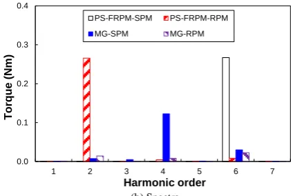
As shown in Fig. 14, the SPM machines generally have higher average electromagnetic torque Tavg than their RPM
counterparts for both the PS-FRPM and MG machines. This can be explained by (24) and (25), since Nip is higher than
pPM as shown in (1) whilst ψp1 and Ip1 are similar. Therefore,
a SPM type machine is recommended to enhance the electric frequency, and hence the back-EMF and torque.
Although the PS-FRPM-SPM machine suffers from 6.98% lower fundamental phase back-EMF than the MG-SPM machine, as shown in Fig. 10, the torque is similar when the copper loss pcu=20W, as shown in Fig. 14 and TABLE VIII.
This can also be explained by (24) and (25), as the PS-FRPM-SPM machine has a 19.39% larger half slot area, i.e. 76.65mm2 and 91.51mm2, and hence electric load than the
MG-SPM machine. More importantly, the average torque difference between the PS-FRPM-SPM and MG-SPM machines becomes higher with copper loss, since the MG-SPM having thinner iron pieces is easier to be saturated.
From the perspective of the higher phase fundamental back-EMF and hence average torque for all applications, the SPM machines are preferred, as shown in Fig. 10, Fig. 11, Fig. 14 and Fig. 15.
(a) Waveforms
(b) Spectra
[image:9.595.315.526.51.193.2]Fig. 14. On-load electromagnetic torque (BLAC, id=0, pcu=20W).
Fig. 15. Average torque versus copper loss (BLAC, id=0).
Besides the average torque, torque ripple is another important torque characteristic in electrical machines especially in those for high performance motion control applications such as direct drive robots [45]. Since the reluctance torques are negligible in the four analyzed machines, Fig. 13, their torque ripples are mainly caused by back-EMF and cogging torque. As for the torque ripple caused by back-EMF, generally, one phase mth (m=1, 2, 3…)
back-EMF will generate (m-1)th and (m+1)th torque ripple
after interacting with the injected fundamental sinusoidal current. However, if three-phase mth back-EMFs are
symmetrical, only the torque ripple harmonics satisfy m+1=3n (n=1, 2, 3…) or m-1=3n (n=1, 2, 3…) remain since the corresponding three-phase phase angles are same, whilst others are eliminated since the corresponding three-phase phase angles are symmetrical.
As shown in TABLE VIII and Fig. 14, the PS-FRPM-RPM machine suffers from the largest torque ripple with a dominant 2nd harmonic, which is caused by the different
three-phase fundamental back-EMFs, as shown in Fig. 10(b). In addition, the high cogging torque of the PS-FRPM-SPM machine shown in Fig. 12 also contributes to the large torque ripple. Although the three-phase back-EMFs are symmetrical, the PS-FRPM-SPM machine also has a higher torque ripple, i.e. 18.56%. This is due to the largest cogging torque in the PS-FRPM-SPM machine, as shown in Fig. 12. Since the cogging torque is low in the SPM and MG-RPM machines, as shown in Fig. 12, their torque ripples are mainly caused by the back-EMFs shown in Fig. 11. The torque ripple in the MG-SPM machine is higher than that of the MG-RPM machine, i.e. 10.43% and 3.01%, respectively. The dominant 4th torque harmonic in the MG-SPM machine
is caused by the three-phase asymmetric 3rd back-EMF
harmonics, as shown in Fig. 11(b). In TABLE VIII, the torque ripple Tr is defined as,
0.0 0.5 1.0 1.5 2.0 2.5
3.0
0 30 60 90 120 150 180
A
v
e
ra
ge
torque
(N
m
)
Current angle (elec. deg.) PS-FRPM-SPM PS-FRPM-RPM MG-SPM
MG-RPM
0 1 2 3 4
0 60 120 180 240 300 360
T
orq
ue
(
N
m
)
Rotor position (elec. deg.)
PS-FRPM-SPM PS-FRPM-RPM
MG-SPM MG-RPM
0.0 0.1 0.2 0.3 0.4
1 2 3 4 5 6 7
T
orque
(N
m
)
Harmonic order
PS-FRPM-SPM PS-FRPM-RPM
MG-SPM MG-RPM
0 1
2
3 4 5 6
0 20 40 60 80 100
A
v
e
ra
ge
torque
(N
m
)
Copper loss (W)
PS-FRPM-SPM PS-FRPM-RPM
𝑇𝑟=
𝑇𝑚𝑎𝑥− 𝑇𝑚𝑖𝑛
𝑇𝑎𝑣𝑔
× 100% (26)
where Tmax and Tmin are the maximum and minimum
electromagnetic torque, respectively.
From the perspective of a more sinusoidal phase back-EMF, a lower cogging torque and a smaller torque ripple, the MG machines are more suitable for wind turbines and motion control applications, as shown in Fig. 10, Fig. 11, Fig. 12 and Fig. 14.
C. Loss and Efficiency
Fig. 16 and Fig. 17 show the iron loss and PM eddy current loss versus rotor speed, respectively. Due to higher gear ratios with higher electric frequencies, the MG-SPM and MG-RPM machines suffer from higher iron loss piron
than the PS-FRPM-SPM and PS-FRPM-RPM machines. However, the PM eddy current loss pPMe of the MG-SPM
and MG-RPM machines are smaller than the PS-FRPM-SPM and PS-FRPM-RPM machines. This is due to the smaller PM bulk volume in the MG-SPM and MG-RPM machines having higher PM pole-pair number. However, the PM eddy current loss pPMe is smaller than the iron loss piron.
Therefore, a smaller gear ratio machine is preferred to achieve a smaller electric frequency and hence iron loss, albeit with a slight higher PM eddy current loss.
It is worth noting that, when the rotor speed is 400rpm, both the iron loss piron and the PM eddy current loss pPMe are
much smaller than the copper loss pcu=20W. This is why in
the global optimization, the iron loss and PM eddy current loss is not accounted. In Fig. 16, the iron loss piron is made
up of three parts, i.e. hysteresis loss phy, eddy current loss ped
and excess loss pex,
𝑝𝑖𝑟𝑜𝑛= 𝑝ℎ𝑦+ 𝑝𝑒𝑑+ 𝑝𝑒𝑥
= 𝑘ℎ𝑦𝑓𝐵𝑚2 + 𝑘𝑒𝑑𝑓2𝐵𝑚2 + 𝑘𝑒𝑥𝑓1.5𝐵𝑚1.5
(27)
where khy, ked and kex are the hysteresis, eddy current and
excess loss coefficients, respectively. They are khy=261.64W/m3, ked=0.10037W/m3, and kex=3.296W/m3,
[image:10.595.305.548.51.246.2]respectively. Bm is the maximum flux density.
Fig. 16. Iron loss versus rotor speed.
TABLE IX lists torque, loss, efficiency characteristics of the four analyzed machines at 400rpm. Generally, the SPM machines can exhibit higher torque and efficiency than the RPM machines, in spite of slightly larger iron loss due to higher electric frequency. The power density of the PS-FRPM-SPM and MG-SPM machines can reach 732665 and 712025 W/m3, respectively. In TABLE IX, T
avg and Pavg are
the average electromagnetic torque and power, respectively, whilst Pout and Tout are the average output torque and power,
respectively, and V is the machine volume. It is worth noting that the efficiency η in TABLE IX is calculated by the
percentage of the output power Pout to the input power Pin,
𝜂 = 𝑃𝑜𝑢𝑡 𝑃𝑖𝑛
× 100% =𝑃𝑎𝑣𝑔− 𝑝𝑖𝑟𝑜𝑛− 𝑝𝑃𝑀𝑒 𝑃𝑎𝑣𝑔+ 𝑝𝑐𝑢
× 100% (28)
Fig. 17. PM eddy current loss versus rotor speed. TABLE IX
TORQUE,LOSS,EFFICIENCY CHARACTERISTICS OF PS-FRPM AND MG MACHINES AT 400RPM
Item Unit PS-FRPM MG
Operation mode - SPM RPM SPM RPM Tavg Nm 2.82 1.52 2.77 2.34
Pavg W 118.3 63.6 116.2 98.0
piron W 1.7 1.2 2.9 2.6
pPMe W 0.096 0.107 0.034 0.034
Pout W 116.5 62.3 113.2 95.4
Tout Nm 2.78 1.49 2.70 2.28
V mm3 159043
Pout/V W/m3 732665 391960 712025 599587
Tout/V Nm/m3 17491 9357 16998 14314
pcu W 20
Pin W 138.3 83.6 136.2 118.0
η % 84.24 74.53 83.13 80.83
D. Winding Inductance and Power Factor
TABLE X lists self-inductance and mutual-inductance of the four analyzed machines. They have similar mutual-inductance, whilst the PS-FRPM-SPM machine has smaller self-inductance than the others three machines, as well as d- and q-axis inductances. As shown in TABLE X, in all the four analyzed machines, d- and q-axis inductances are similar and hence the reluctance torques are negligible, as shown in Fig. 13. This is due to the d- and q-axis similar magnetic paths via iron pieces and inner PM body.
TABLE X
INDUCTANCES PS-FRPM AND MGMACHINES
Item Unit PS-FRPM MG
Operation mode mH SPM RPM SPM RPM Self-inductance, LAA mH 0.17 0.21 0.22 0.23
Mutual-inductance, MBA mH -0.08 -0.09 -0.10 -0.10
Mutual-inductance, MCA mH -0.08 -0.09 -0.10 -0.10
d-axis inductance, Ld mH 0.23 0.30 0.33 0.33
[image:10.595.307.549.191.404.2]q-axis inductance, Lq mH 0.26 0.30 0.32 0.33
Fig. 18. Phasor diagram with id=0.
Based on the phasor diagram shown in Fig. 18 in which phase resistance voltage drop is neglected, the power factors of the four analyzed machines are listed in TABLE XI as cosine value of the angle φ, i.e. cos(φ). In Fig. 18, Eph is the
open-circuit phase back-EMF. Uph is the on-load phase
0 10 20 30 40
50 60
0 800 1600 2400 3200 4000
Iron
loss
(
W
)
Rotor speed (rpm) PS-FRPM-SPM
PS-FRPM-RPM
MG-SPM
MG-RPM
0 2 4 6 8 10 12
0 800 1600 2400 3200 4000
P
M
l
oss
(
W
)
Rotor speed (rpm) PS-FRPM-SPM
PS-FRPM-RPM
MG-SPM
MG-RPM
jXqIq
Eph
Uph=1+j0 O
φ
[image:10.595.57.279.512.648.2] [image:10.595.306.547.546.720.2]terminal voltage. Xq is the q-axis reactance. Iq is the q-axis
current. All of these parameters are in per unit (p.u.) value. As listed in TABLE XI, the PS-FRPM-SPM machine has similar power factor as its RPM counterpart, and the MG-SPM and MG-RPM machines have similar power factor as well. However, due to higher gear ratios with higher electric frequencies, both MG-SPM and MG-RPM machines suffer from lower power factor. This makes challenges to the inverter power rating. Therefore, from the perspective of a smaller inverter power rating, the PS-FRPM machines are recommended for the EVs and HEVs, since they feature higher power factors, as shown in TABLE XI.
TABLE XI
SYNCHRONOUS REACTANCE AND POWER FACTOR OF PS-FRPM AND MG MACHINES AT 400RPM
Item PS-FRPM MG
Operation mode SPM RPM SPM RPM Synchronous reactance 0.58 0.62 0.90 0.90
Power factor 0.81 0.78 0.45 0.43
IV. EXPERIMENTAL VALIDATION
In the foregoing analysis, electromagnetic performance of the PS-FRPM machine and the conventional MG machine operating in both SPM and RPM modes are comprehensively compared by FE analyses. FE results show that the PS-FRPM machine operating in SPM mode exhibits higher torque, efficiency, and power factor than its RPM counterpart. The experiment results of the PS-FRPM-SPM prototype machine have been reported in [43] in terms of phase back-EMF waveforms and static torques. Here, the MG-RPM machine is built and the phase back-EMF, static torque, and winding inductances including both self- and mutual-inductances are tested. These measured results will be presented together with comparison to those of the PS-FRPM-SPM prototype to verify the FE predicted results.
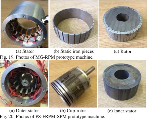
Fig. 19 and Fig. 20 show the pictures of the two prototypes, respectively. Both prototypes are wound with number of turns per phase Nph=72. It is worth noting that to
ease manufacturing, the PM thickness is modified to 4mm in both machines. Also, for easier assembling the rotor iron pieces, an iron bridge of thickness 0.5mm is introduced adjacent to the inner air-gap to connected iron pieces in both prototypes.
(a) Stator (b) Static iron pieces (c) Rotor Fig. 19. Photos of MG-RPM prototype machine.
[image:11.595.313.531.137.431.2](a) Outer stator (b) Cup-rotor (c) Inner stator Fig. 20. Photos of PS-FRPM-SPM prototype machine.
Fig. 21 shows the comparison of the measured and 2D FE predicted phase back-EMFs, from which it can be observed that 2D FE predicted values are slightly lower than the measured ones due to end effect in both machines. As shown
in Fig. 21, the measured phase back-EMF of the PS-FRPM-SPM prototype is more than twice of that of the MG-RPM prototype. It is worth noting that the phase fundamental back-EMF dropped 53.83% in the MG-RPM machine, due to the introduction of the 0.5mm iron bridge for the static iron pieces which is one third of the total thickness of iron pieces, i.e. 1.5mm.
(a) Waveforms
[image:11.595.59.280.218.265.2](b) Spectra
Fig. 21. Comparison of measured and 2D FE predicted phase back-EMFs in MG-RPM and PS-FRPM-SPM machines at 400rpm.
(a) MG-RPM
(b) PS-FRPM-SPM
Fig. 22. Comparison of measured and 2D FE predicted torque variations with rotor position (Ia= -2Ib= -2Ic).
-4 -2
0
2 4
0 60 120 180 240 300 360
B
a
c
k
-E
M
F
(V
)
Rotor position (elec. deg.)
MG-RPM, 2D FE
MG-RPM, MEA PS-FRPM-SPM, 2D FE PS-FRPM-SPM, MEA
0 1 2 3 4
1 2 3 4 5 6 7 8 9 10
B
a
c
k
-EM
F
(V)
Rotor position (elec. deg.) MG-RPM, 2D FE
MG-RPM, MEA
PS-FRPM-SPM, 2D FE
PS-FRPM-SPM, MEA
0.0 0.5 1.0 1.5
0 30 60 90 120 150 180
T
orque
(N
m
)
Rotor position (elec. deg.)
Ia=15A, 2D FE Ia=15A, MEA
Ia=10A, 2D FE Ia=10A, MEA
Ia=5A, 2D FE Ia=5A, MEA
0.0 0.5 1.0 1.5
2.0 2.5
0 30 60 90 120 150 180
T
orque
(N
m
)
Rotor position (elec. deg.)
Ia=15A, 2D FE Ia=15A, MEA
Ia=10A, 2D FE Ia=10A, MEA
[image:11.595.314.531.453.751.2] [image:11.595.46.289.548.745.2]Fig. 23. Comparison of measured and 2D FE predicted peak static torque with phase A current Ia (Ia= -2Ib= -2Ic).
(a) MG-RPM
(b) PS-FRPM-SPM
Fig. 24. Comparison of measured and 2D FE predicted self- and mutual- inductances.
The static torques with current angle of the prototype machines are measured based on the test method reported in [46]. Fig. 22 shows the comparison of the measured and 2D FE predicted torque variations with rotor position. As for the peak torque, the comparison between the measured and 2D FE predicted results under different phase A current Ia is
shown in Fig. 23. Again, the 2D FE predicted and measured static torques agree well with each other, although the 2D FE predicted results are slightly smaller in both prototypes due to end effect. As shown in Fig. 22 and Fig. 23, the measured static torque of the PS-FRPM-SPM prototype is higher than that of the MG-RPM prototype. Nevertheless, the MG-RPM prototype is easier to be saturated than the PS-FRPM-SPM prototype, as predicted by FE in Fig. 15. It is worth noting that in the measurement of static torque, three-phase currents Ia, Ib, and Ic are set as,
𝐼𝑎= −2𝐼𝑏 = −2𝐼𝑐 (29) For the winding inductances including both self- and mutual-inductance, the comparison between the 2D FE predicted values and those measured by LCR meter are shown in Fig. 24. It is worth noting that the self-inductance shown in Fig. 24 is directly measured by the Hioki-LCR
meter 3522 at 20°C, whilst the mutual-inductance between
phase A and B, M is calculated by,
𝑀 =𝐿𝐴+𝐵− 𝐿𝐴− 𝐿𝐵
2 (30)
where LA+B is the self-inductance when the windings of
phase A and phase B are serially connected. LA is the
self-inductance of phase A winding. LB is the self-inductance of
phase B winding.
As can be observed from Fig. 24, the mutual-inductance predicted by 2D FE and those calculated based on (30) agree well with each other in both prototypes. However, the 2D FE predicted self-inductance is slightly smaller than the measured one. This can be explained as follows. Since the 2D FE predicted self-inductance cannot account for the end winding inductance, it is slightly smaller than that measured by LCR meter [47]. However, this influence can be eliminated based on (30) for the calculation of the mutual-inductance between phase A and B, MBA. Therefore, the 2D
FE predicted mutual-inductance and that calculated based on on (30) agree well with each other in both prototypes.
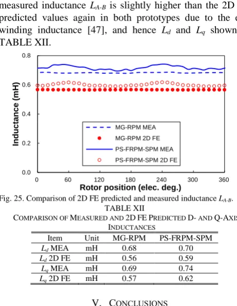
It is worth noting that the FE predicted and measured inductances shown in Fig. 24 are obtained at a low phase current, i.e. 0.1A. The d- and q-axis inductances of both prototypes at rated condition are also tested based on the standstill frequency response method [48]. The d- and q-axis inductances Ld and Lq can be obtained as the values of the
inductance LA-B, i.e. the self-inductance when the windings
of phase A and phase B are oppositely connected, at d- and q-axis positions, respectively [48]. As shown in Fig. 25, the measured inductance LA-B is slightly higher than the 2D FE
predicted values again in both prototypes due to the end winding inductance [47], and hence Ld and Lq shown in
[image:12.595.57.274.50.187.2]TABLE XII.
Fig. 25. Comparison of 2D FE predicted and measured inductance LA-B.
TABLE XII
COMPARISON OF MEASURED AND 2DFEPREDICTED D- AND Q-AXIS INDUCTANCES
Item Unit MG-RPM PS-FRPM-SPM Ld MEA mH 0.68 0.70
Ld 2D FE mH 0.56 0.59
Lq MEA mH 0.69 0.74
Lq 2D FE mH 0.57 0.62
V. CONCLUSIONS
The PS-FRPM and MG machines operating in SPM and RPM modes are comparatively analyzed in this paper. The comparison results can be summarized as
(1) The PS-FRPM-SPM and PS-FRPM-RPM machines have smaller flux-leakage and hence higher main flux than the MG-SPM and MG-RPM machines, due to the smaller iron piece number and PM pole-pair number. 0
1 2 3 4
0 5 10 15 20 25
T
orq
ue
(
N
m
)
Phase A current Ia (A) MG-RPM, 2D FE
MG-RPM, MEA PS-FRPM-SPM, 2D FE PS-FRPM-SPM, MEA
-0.2 -0.1 0.0 0.1
0.2
0.3
0 60 120 180 240 300 360
L
a
nd
M
(
m
H
)
Rotor position (elec. deg.) Self inductance MEA Self-inductance 2D FE Mutual inductance MEA Mutual inductance 2D FE
-0.2 -0.1 0.0 0.1
0.2
0.3
0 60 120 180 240 300 360
L
a
nd
M
(
m
H
)
Rotor position (elec. deg.) Self inductance MEA
Self-inductance 2D FE
Mutual inductance MEA Mutual inductance 2D FE
0.0 0.2
0.4
0.6 0.8
0 60 120 180 240 300 360
Induct
a
nce
(
m
H
)
[image:12.595.55.276.208.506.2] [image:12.595.306.537.397.696.2](2) The PS-FRPM-SPM and MG-SPM machines have higher fundamental back-EMFs than their RPM counterparts, respectively, due to the larger electric frequency since the iron piece number is larger than the PM pole-pair number. The MG-SPM machine has the highest phase fundamental back-EMF, whilst the MG-RPM features the lowest phase back-EMF harmonics. (3) The MG-SPM and MG-RPM machines have much
smaller cogging torque than the PS-FRPM-SPM and PS-FRPM-RPM machines, due to similar PM pole-pair number and iron piece number.
(4) The PS-FRPM-SPM and MG-SPM machines have higher average torque than the PS-FRPM-RPM and MG-RPM machines at the rated condition. However, the MG-SPM machine is easier to be saturated than the PS-FRPM-SPM machine, due to the thinner iron pieces. The PS-FRPM-RPM machine suffers from the highest torque ripple due to the unbalanced magnetic circuit and high cogging torque. The MG-RPM machine has the smallest torque ripple, resulting from the low back-EMF harmonics and also the small cogging torque. (5) The MG-SPM and MG-RPM machines suffer from
higher iron loss than the FRPM-SPM and PS-FRPM-RPM machines, due to the higher electric frequency. However, the MG-SPM and MG-RPM machines have less PM eddy current loss as a result of the smaller PM bulk volumes. The PS-FRPM-SPM and MG-RPM machines have higher efficiency than the PS-FRPM-RPM and MG-SPM machines, due to the larger average torque.
(6) All the four analyzed machines have similar d- and q -axis inductances and hence the negligible reluctance torque. The PS-FRPM-SPM and PS-FRPM-RPM machines have higher power factor than the MG-SPM and MG-RPM machines, due to the less flux-leakage. Overall, in designing a MG machine for various applications, two general design guides regarding: (a) a SPM or RPM type machine and (b) a higher or smaller gear ratio machine are given as follows, respectively.
(1) A SPM type machine is recommended to enhance the electric frequency, and hence phase back-EMF and torque.
(2) As for EVs or HEVs, a smaller gear ratio machine is preferred to reduce the flux-leakage for obtaining a higher power factor and a smaller iron loss, albeit with a slightly higher PM eddy current loss. However, if a lower cogging torque and a smaller torque ripple are desired, higher gear ratio machines are recommended for wind turbines and motion control applications.
REFERENCES
[1] Z. Q. Zhu, and D. Howe, “Electrical machines and drives for electric, hybrid and fuel cell vehicles,” Proc. IEEE, vol. 95, no. 4, pp. 746-765, Apr. 2007.
[2] K. T. Chau, C. C. Chan, and C. H. Liu, “Overview of permanent-magnet brushless drives for electric and hybrid electric vehicles,” IEEE Trans. Ind. Electron., vol. 55, no. 6, pp. 2246-2257, Jun. 2008. [3] M. Cheng, W. Hua, J. Zhang, and W. Zhao, “Overview of
stator-permanent magnet brushless machines,” IEEE Trans. Ind. Electron., vol. 58, no. 11, pp. 5087-5101, Nov. 2011.
[4] T. M. Jahns, G. B. Kliman, Thomas W. Neumann, “Interior permanent-magnet synchronous motors for adjustable-speed drives,” IEEE Trans. Ind. Appl., vol. IA-22, no. 4, pp. 738-747, Jul. 1986.
[5] N. Bianchi, and S. Bolognani, “Design techniques for reducing the cogging torque in surface-mounted PM motors,” IEEE Trans. Ind. Appl., vol. 38, no. 5, pp. 1259-1265, Sep./Orc. 2002.
[6] A. M. El-Refaie, T. M. Jahns, and D. W. Novotny, “Analysis of surface permanent magnet machines with fractional-slot concentrated windings,” IEEE Trans. Energy Convers., vol. 21, no. 1, pp. 34-43, Mar. 2006.
[7] J. Cros, and P. Viarouge, “Synthesis of high performance PM motors with non-overlapping windings,” IEEE Trans. Energy Convers., vol. 17, no. 2, pp. 248-253, Jun. 2002.
[8] Z. Z. Wu, and Z. Q. Zhu, “Analysis of air-gap field modulation and magnetic gearing effects in switched flux permanent magnet machines,” IEEE Trans. on Magn., vol. 51, no. 5, pp. 1-12, May 2015, Art. ID 8105012.
[9] M. Freddy, and L. Heinz, “Parasitic effects in PM machines with concentrated windings,” IEEE Trans. Ind. Appl., vol. 43, no. 5, pp. 1223–1232, Sep./Oct. 2007.
[10] R. Qu, D. Li, and J. Wang, “Relationship between magnetic gears and vernier machines,” in Proc. Int. Conf. Electr. Mach. Syst., Beijing, China, 2011, pp. 1-6.
[11] J. Li, K. T. Chau, and W. Li, “Harmonic analysis and comparison of permanent magnet vernier and magnetic-geared machines,” IEEE Trans. Magn., 47, no. 10, pp. 3649-3652, Oct. 2011.
[12] S. L. Ho, S. Niu, and W. N. Fu, “Design and comparison of vernier permanent magnet machines,” IEEE Trans. Magn., vol. 47, no. 10, pp. 3280-3283, Oct. 2011.
[13] D. Li, R. Qu, W. Xu, J. Li, and T. A. Lipo, “Design procedure of dual-stator, spoke-array vernier permanent magnet machines,” IEEE Trans. Ind. Appl., vol. 51, no. 4, pp. 2972-2983, Jul.-Aug. 2015.
[14] K. Atallah, and D. Howe, “A novel high-performance magnetic gear,” IEEE Trans. Magn., vol. 37, no. 4, pp. 2844-2846, Jul. 2001. [15] K. Atallah, S. D. Calverley, and D. Howe, “Design, analysis and
realisation of a high-performance magnetic gear,” IEE Proc.Electric Power Appl., vol. 151, no. 2, pp. 135-143, Mar. 2004.
[16] P. O. Rasmussen, T. O. Andersen, F. T. Jorgensen, and O. Nielsen, “Development of a high-performance magnetic gear,” IEEE Trans. Ind. Appl., vol. 41, no. 3, pp. 764-770, May-Jun. 2005.
[17] L. N. Jian, and K. T. Chau, “A coaxial magnetic gear with Halbach permanent-magnet arrays,” IEEE Trans. Energy Convers., vol. 25, no. 2, pp. 319-328, Jun. 2010.
[18] L. Wang, J. Shen, Y. Wang, and K. Wang, “A novel magnetic-geared outer-rotor permanent-magnet brushless motor,” in Proc. of Power Electro. Mach. and Dri., Yoke, UK, 2008. pp. 33-36.
[19] K. Atallah, J. Rens, S. Mezani, and D. Howe, “A novel “Pseudo” direct-drive brushless permanent magnet machine,” IEEE Trans. Magn., vol. 44, no. 11, pp. 4349-4352, Nov. 2008.
[20] L. Li, W. N. Fu, and S. L. Ho, S. Niu, and Y. Li, “A quantitative comparison study of power-electronic-driven flux-modulated machines using magnetic field and thermal field co-simulation,” IEEE Trans. Ind. Electron., vol. 62, no. 10, pp. 6076-6084, Oct. 2015. [21] K. T. Chau, D. Zhang, J. Z. Jiang, C. Liu and Y. Zhang, “Design of a
magnetic-geared outer-rotor permanent-magnet brushless motor for electric vehicles,” IEEE Trans. Magn., vol. 43, no. 6, pp. 2504-2506, Jun. 2007.
[22] K. Atallah, J. Wang, S. D. Calverley, and S. Duggan, “Design and operation of a magnetic continuously variable transmission,” IEEE Trans. Ind. Appl., vol. 48, no. 4, pp. 1288-1295, Jul.-Aug. 2012. [23] A. Penzkofer, and K. Atallah, “Analytical modeling and optimization
of pseudo-direct drive permanent magnet machines for large wind turbines,” IEEE Trans. Magn., vol. 51, no. 12, Dec. 2015, Art. ID 8700814.
[24] L. Jian, K. T. Chau, and J. Z. Jiang, “A magnetic-geared outer-rotor permanent-magnet brushless machine for wind power generation,” IEEE Trans. Ind. Appl., vol. 45, no. 3, pp. 954-962, May-Jun. 2009. [25] R. Montague, C. Bingham, and K. Atallah, “Servo control of magnetic
gears,” IEEE/ASME Trans.Mech., vol. 17, no. 2, pp. 269-278, Apr. 2012.
[26] S. Gerber, and R. Wang, “Design and evaluation of a magnetically geared PM machine,” IEEE Trans. Magn., vol. 51, no. 8, Art. ID 8107010, Aug. 2015
[27] J. M. Crider, and S. D. Sudhoff, “An inner rotor flux-modulated permanent magnet synchronous machine for low-speed high-torque applications,” IEEE Trans. Energy Convers., vol. 30, no. 3, pp. 1247-1254, Sep. 2015.
[28] Q. Wang, and S. Niu, “A novel hybrid-excited dual-PM machine with bi-directional flux modulation,” IEEE Trans. Energy Convers., in press.