Novel damage free self centering column base connection for earthquake resilient steel buildings
Full text
Figure
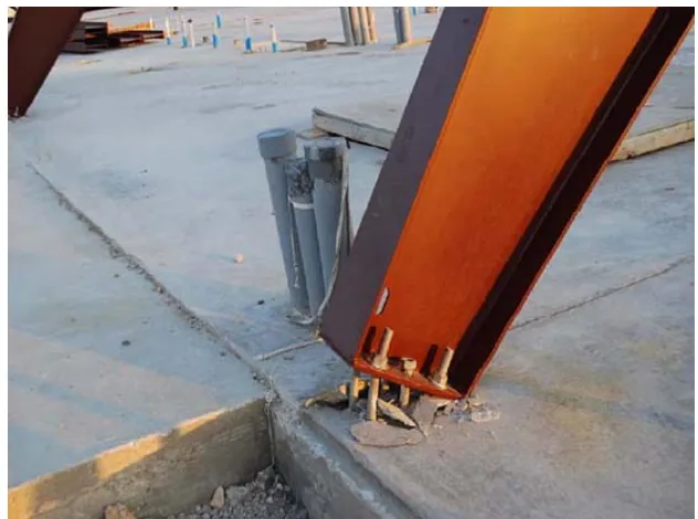
![Figure 1.9 Shear key/lug failure due to shear force from the concrete foundation [after Aguirre and Palma (2009)]](https://thumb-us.123doks.com/thumbv2/123dok_us/9493208.455157/61.595.123.522.90.463/figure-shear-failure-shear-concrete-foundation-aguirre-palma.webp)
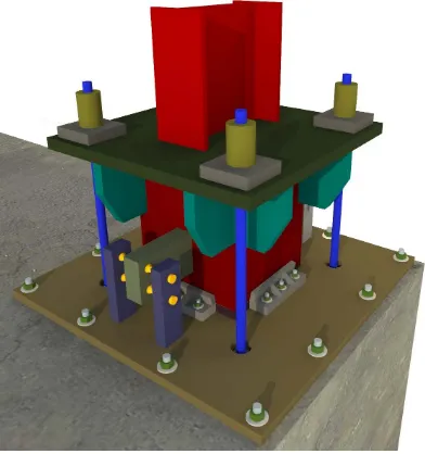
![Figure 3.1 Three-dimensional representation of the proposed column base with 8 WHPs [figure designed in SketchUp (Trimble, 2016)]](https://thumb-us.123doks.com/thumbv2/123dok_us/9493208.455157/102.595.120.517.291.570/figure-dimensional-representation-proposed-column-designed-sketchup-trimble.webp)
Outline
Related documents
Standardization of herbal raw drugs include passport data of raw plant drugs, botanical authentification, microscopic & molecular examination, identification of
She is currently Instructor of structural geology and tectonics at the earth sciences department of the Islamic Azad University, Fars science and research
National Conference on Technical Vocational Education, Training and Skills Development: A Roadmap for Empowerment (Dec. 2008): Ministry of Human Resource Development, Department
The summary resource report prepared by North Atlantic is based on a 43-101 Compliant Resource Report prepared by M. Holter, Consulting Professional Engineer,
Sensory or Motor Stage 2 is that the pairing of stimuli leads to conditioning (Commons, Miller, Commons- Miller, & Chen, 2012). Unlike at Stage 1, the responses begin to be
During the software development process, the Coopera- tion Manager supports a team in planning collaborative work, provides to-do lists and informal communication, allows the
Secondary outcome measures were the percentage of patients in each group whose DAS28 improved by ⬎ 1.2, the percentage of patients who achieved a 20% improvement in the ACR core
The situation that provokes workplace violence does not necessarily have to start in the workplace or and the act of violence does not necessarily have to happen in the workplace
