University of Warwick institutional repository: http://go.warwick.ac.uk/wrap
A Thesis Submitted for the Degree of PhD at the University of Warwick
http://go.warwick.ac.uk/wrap/60562
This thesis is made available online and is protected by original copyright. Please scroll down to view the document itself.
Underwater Optical Wireless Sensor
Network
By
Zahir Uddin Ahmad
A thesis submitted in partial fulfilment of the requirements for the degree of
Doctor of Philosophy
School of Engineering
Table of Contents
Table of Contents ... i
List of figures ... ix
List of tables... xv
List of abbreviations ... xvi
Acknowledgements...xviii
Declaration... xx
Abstract... xxi
Publications associated with this research work ...xxiii
Chapter1 : Introduction... 1
1.1 Overview ... 1
1.2 Motivation ... 2
1.2.1 Ocean biology ... 2
1.2.3 Surveillance system... 3
1.2.4 Seismic monitoring ... 3
1.2.5 Ship hull and equipment monitoring... 4
1.2.6 AUV/ROV operation ... 4
1.2.7 Communicating with submarine/diver... 4
1.3 Application scenario... 4
1.4 Problem statement ... 6
1.5 Approach ... 8
1.6 Contributions ... 9
1.7 Application limit... 10
1.8 Outline of the thesis... 11
Chapter2 : Background research and related work ... 13
2.1 Introduction ... 13
2.2 Communication requirements for underwater network... 14
2.3 Possible options for underwater communication carriers ... 16
2.3.1 Research outcome of underwater radio communications ... 16
2.3.2 Acoustic communication... 19
2.3.3 Underwater optical wireless communication ... 21
2.4 Attenuation of optical wireless underwater... 25
2.4.1 Absorption modelling ... 26
2.5 Issues related to system deign ... 31
2.5.1 LED or Laser? ... 31
2.5.2 Photon detector selection ... 33
2.5.3 Modulation techniques ... 35
2.6 Different types of link for underwater optical wireless... 39
2.7 Conclusion... 42
Chapter3 : Transceiver design and testing ... 44
3.1 Introduction ... 44
3.2 Block diagram of the transceiver... 45
3.3 Transmitter circuit design... 46
3.3.1 LED selection and Frequency response ... 47
3.3.2 LED driver circuit ... 50
3.4 Receiver design ... 51
3.4.1 Photodiode selection ... 51
3.4.2 Receiver circuit configuration... 52
3.4.3 Bootstrap front end... 54
3.4.4 Transimpedance front end... 56
3.5 Amplifier circuit ... 60
3.6 Performance analysis of the designed transceiver... 61
3.6.1 Loss of the link... 61
3.6.3 Noise characteristic ... 63
3.6.4 Comparison of air test with water testing ... 66
3.7 Testing the built transceiver ... 68
3.7.1 Audio source ... 70
3.7.2 Audio preamplifier ... 70
3.7.3 Oscillator ... 70
3.7.4 Pulse width modulator ... 71
3.7.5 LED driver circuit ... 71
3.7.6 Receiver circuit ... 72
3.7.7 Test results ... 72
3.8 Conclusion... 73
Chapter4 : Multi-hop network design and implementation... 74
4.1 Introduction ... 74
4.2 Sensor network performance objective ... 75
4.2.1 Low power consumption... 75
4.2.2 Low cost ... 76
4.2.3 Network topology ... 76
4.2.4 Security ... 77
4.2.5 Data throughput... 77
4.2.6 Message latency ... 77
4.3 Underwater sensor network architecture ... 78
4.3.1 Physical layer development... 83
4.3.2 Pairing green and blue transceiver ... 84
4.4 Sensor node architecture ... 85
4.4.1 Microcontroller selection ... 86
4.4.2 Communication unit and interface selection... 87
4.4.3 Sensors and sensor interface design ... 88
4.4.4 Power source module design... 89
4.4.5 Hardware implementation of the sensor node... 90
4.5 Software design for the sensor node... 92
4.6 Gateway node design... 94
4.7 Software design for Gateway node ... 96
4.8 Multi-hop network prototype ... 98
4.8.1 Example of an operation scenario of multi-hop system... 98
4.9 Conclusion... 102
Chapter5 : MAC protocol design... 103
5.1 Introduction ... 103
5.2 Overview of existing underwater MAC protocols ... 104
5.2.1 Underwater acoustic MAC... 105
5.2.2 Underwater MAC for radio communications ... 107
5.3 Directional MAC concept ... 110
5.4 Proposed TDMA based Directional MAC protocol... 113
5.4.1 Some assumptions... 113
5.4.2 Basic idea ... 114
5.4.3 Data collection scenario ... 118
5.4.4 MAC address assignment... 119
5.4.5 Synchronization protocol ... 120
5.4.6 Normal operation scenario of the proposed MAC ... 120
5.4.7 Emergency scenario ... 122
5.5 Different types of frame design ... 122
5.5.1 Data frame... 123
5.5.2 MAC request and reply frame... 124
5.5.3 Synchronization frame ... 125
5.5.4 Other control frames ... 125
5.6 Hidden terminal problem... 126
5.7 Performance analysis of the proposed MAC... 127
5.7.1 Throughput efficiency... 127
5.7.2 Node power consumption ... 129
5.7.3 Delay analysis ... 131
5.8 Conclusion... 133
6.1 Introduction ... 134
6.2 Experimental setup ... 135
6.3 Performance analysis in air ... 136
6.3.1 Received optical power at different communication range... 136
6.3.2 Success rate for different optical power... 137
6.3.3 Single hop Success rate for different communication range... 138
6.3.4 Single hop test for different transmission rate ... 139
6.3.5 Success rate for the different angle ... 140
6.3.6 Success rate for a multi-hop system in air ... 141
6.3.7 Number of hops vs. Success rate... 141
6.4 Performance analysis for a single hop system through water ... 142
6.4.1 Water tank setup... 142
6.4.2 Tap water testing ... 143
6.4.3 Canal water testing... 144
6.4.4 Sea water testing ... 147
6.5 Comparison between different water testing... 148
6.5.1 Received power vs. Communication range... 148
6.5.2 Success rate vs. Communication distance... 148
6.6 Multi-hop water testing ... 149
6.6.1 Performance analysis using lenses ... 150
Chapter7 : Conclusion and future work ... 152
7.1 Conclusions ... 152
7.2 Future work ... 156
References... ... 158
List of figures
Figure 1-1 Application scenario... 5
Figure 2-1 Signal strength as a function of transmitter antenna ... 18
Figure 2-2 A vertical profile of sound speed as a function of depth... 20
Figure 2-3 Functional block diagram of total attenuation... 26
Figure 2-4 Light absorption in water ... 28
Figure 2-5 Light scattering coefficient of sea water ... 30
Figure 2-6 Received optical power vs. communication range... 31
Figure 2-7 Light power versus current characteristics of Laser and LED ... 32
Figure 2-8 Optical power spectra of common ambient infrared sources ... 33
Figure 2-9 Comparison of (a) NRZ-OOK Pulse (b) RZ-OOK Pulse with duty cycle 0.5... 36
Figure 2-10 Transmitted waveform of 4-PPM... 37
Figure 2-12 Links for optical wireless communication network ... 39
Figure 2-13 BER performance of two types of communication link underwater... 41
Figure 2-14 Reflection communication scenario ... 42
Figure 3-1 Block diagram of an underwater optical wireless transceiver... 45
Figure 3-2 Basic optical wireless transmitter... 47
Figure 3-3 A simple optical wireless receiver... 48
Figure 3-4 Frequency response of two LEDs ... 49
Figure 3-5 Frequency response of different coloured Avago LEDs ... 50
Figure 3-6 Digital optical wireless transmitter... 50
Figure 3-7 Bootstrap front end... 55
Figure 3-8 Frequency response of bootstrap amplifier ... 55
Figure 3-9 Basic transimpedance pre-amplifier... 56
Figure 3-10 Single transistor transimpedance amplifier ... 57
Figure 3-11 Gain of the TIA receiver using different transistor ... 59
Figure 3-12 Feedback resistor vs. output volts ... 59
Figure 3-13 Voltage amplifier for optical wireless receiver ... 60
Figure 3-14 Image of the transceiver ... 61
Figure 3-15 Link gain in different communication range ... 62
Figure 3-16 Maximum possible bit-rate of the transceiver... 63
Figure 3-17 Noise source in photon detection system ... 64
Figure 3-19 Water test setup ... 67
Figure 3-20 Comparison between output voltage at receiver (Left side through air and Right side through water tank ... 68
Figure 3-21 Block diagram of an underwater optical wireless audio transmission system... 69
Figure 3-22 Audio pre-amplifier... 70
Figure 3-23 LM 386 as an oscillator ... 71
Figure 3-24 555IC as a Pulse width modulator... 71
Figure 3-25 Receiver circuit for an underwater audio transmission system ... 72
Figure 3-26 Built transceiver for transmitting audio signal underwater ... 73
Figure 4-1 General underwater acoustic network architecture ... 79
Figure 4-2 Star topology based network architecture ... 80
Figure 4-3 Possible multi-hop network architecture... 81
Figure 4-4 Adopted network architecture for multi-hop underwater optical wireless sensor network ... 82
Figure 4-5 Physical layer structure of the multi-hop underwater optical wireless sensor network a) Simplex, b) Half-duplex, and c) Full duplex ... 83
Figure 4-6 Pairing two different types of transceivers... 84
Figure 4-7 Sensor node architecture block... 85
Figure 4-8 LM35 interface with ATmega 1284 ... 89
Figure 4-9 Schematic layout of the sensor node ... 90
Figure 4-11 Side view of the built sensor node... 91
Figure 4-12 Flow chart of sensor node’s main program ... 93
Figure 4-13 Gateway node architecture ... 94
Figure 4-14 Built gateway node... 95
Figure 4-15 Block diagram of gateway node’s main program ... 97
Figure 4-16 Multi-hop system setup ... 98
Figure 4-17 Physical layer connection of the built prototype ... 99
Figure 4-18 Wave form in different stages of a multi-hop network ... 100
Figure 4-19 RealTerm software showing the received character in the gateway node ... 101
Figure 5-1 Network scenario for underwater acoustic MAC... 105
Figure 5-2 A TDMA based protocol for underwater radio communication ... 107
Figure 5-3 RTS/CTS based directional MAC ... 111
Figure 5-4 TDMA frame format ... 115
Figure 5-5 Data gathering scenario ... 118
Figure 5-6 MAC assignment procedure... 119
Figure 5-7 Operation scenario of the proposed MAC... 121
Figure 5-8 Detailed data frame format... 123
Figure 5-9 MAC request frame ... 124
Figure 5-10 MAC reply frame ... 125
Figure 5-12 Control frame format... 126
Figure 5-13 Hidden terminal problem... 127
Figure 5-14 Throughput for different payload size... 128
Figure 5-15 Total power consumption for one hour ... 130
Figure 5-16 Round trip time for different packet size ... 132
Figure 5-17 Round trip time for different transmission rate ... 133
Figure 6-1 Experimental setup for performance evaluation ... 135
Figure 6-2 Received optical power at different distances ... 136
Figure 6-3 Received optical power with and without presence of room light ... 137
Figure 6-4 Success rate for different optical power ... 137
Figure 6-5 Success rate in air for a single hop system... 138
Figure 6-6 Success rate for various transmission rates ... 139
Figure 6-7 Success rate for different transmission angles ... 140
Figure 6-8 Success rate for multi-hop communication range ... 141
Figure 6-9 Side, bottom and top of the water surface is covered with black paint. 143 Figure 6-10 Success rate for tap water... 144
Figure 6-11 Canal water collection from Coventry canal ... 145
Figure 6-12 Success rate for different communication ranges... 145
Figure 6-13 Success rate for different range without covering the surface ... 146
Figure 6-14 Water collection from Irish Sea at Blackpool ... 147
Figure 6-16 Frame success rate for different communication distance ... 149
List of tables
Table 2-1 Communication requirements for different underwater networks... 15
Table 2-2 Advantage and disadvantage of different communication carriers underwater... 17
Table 2-3 Summary of different underwater optical wireless communications research ... 22
Table 2-4 Comparison between acoustic, RF and optical medium underwater... 25
Table 2-5 Comparison between Laser diode and LED ... 32
Table 2-6 Comparison of photon detectors ... 34
Table 2-7 Comparison of various modulation techniques for optical wireless communication... 38
Table 3-1 Comparison between two Photodiodes... 52
List of abbreviations
ADC- Analogue to Digital Converter
APD- Avalanche Photodiode
AUV- Autonomous Underwater Vehicles
BER- Bit Error Rate
BPSK- Binary Phase Shift Keying
CDMA- Code Division Multiple Access
CSMA- Carrier Sense Multiple Access
CTS- Clear to Send
DSSS- Direct Sequence Spread Spectrum
FDMA- Frequency Division Multiple Access
FM- Frequency Modulation
FOV- Field of View
IrDA- Infrared Data Association
LED- Light Emitting Diodes
LOS- Line of Sight
MAC- Medium Access Control
MSB- Most Significant Bit
NRZ- Non Return to Zero
OFDM- Orthogonal Frequency Division Multiplexing
OOK- On Off Keying
OW- Optical Wireless
PPM- Pulse Position Modulation
PSU- Practical Salinity Unit
QOS- Quality of Service
QPSK- Quadrature Phase Shift Keying
RF- Radio frequency
RISC- Reduced Instruction Set computing
ROV- Remotely Operated Vehicles
RZ- Return to Zero
RTS- Request to Send
SNR- Signal to Noise Ratio
SPI- Serial Peripheral Interface
TDMA- Time Division Multiple Access
TTL- Time to Live
Acknowledgements
First of all, I thank God, for giving me knowledge and strength to complete this PhD
thesis. The completion of the thesis would not be possible without the support and
encouragement of many individuals. I thank all the people who have supported me
throughout my PhD study.
I wish to express my sincere gratitude to my supervisor Professor Roger Green for
his priceless support, guidance and suggestions throughout my study time here at
Warwick. It was a great privilege to work under his supervision, and I was really
fortunate to have him as my PhD supervisor. I would also like to thank Professor
Evor Hines for being my second supervisor. I also thank all the staff of the
University of Warwick, who has directly and indirectly contributed to this work. I
also want to acknowledge the technical support facilities from the School of
Engineering at University of Warwick.
I want to extend my appreciation to my colleagues in the Comsys Lab for their
valuable suggestions and constructive discussions throughout. I would also like to
things together.
Above all, I can never express my gratefulness enough to my parents, wife, brothers,
and other family members here in UK and in Bangladesh. My father (May God,
grant him heaven) always encouraged me to go for the highest degree on earth. I do
believe that, he is watching my success from the heaven. My mother and brothers
always believed on my ability and supported right the way through. I am really
grateful to them. All my family members in Bangladesh, USA and here in the UK
supported me throughout my time here; I want to thank all of them for their valuable
suggestions. My wife, Fatema Zannat had a very tough time and had to give up her
career because of my PhD study. I thank her for her continuous support and endless
love during all these years. Last but not least, I want to mention about my one year
old son, Zarif Ahmad. He was my source of inspiration and enthusiasm during the
Declaration
This thesis is submitted in partial fulfilment for the degree of Doctor of Philosophy
under the regulations set out by the Graduate School at the University of Warwick.
All work reported in the thesis has been carried out by Zahir Uddin Ahmad, except
where stated otherwise, between the dates of November 2009 and September 2013.
No part of this thesis has been previously submitted to the University of Warwick or
any other academic institution for admission to a higher degree.
Abstract
The thesis details the development of a short range, multi-hop underwater optical
wireless sensor network. Multi-hop underwater optical wireless communication
using a line of sight (LOS) link can provide a greater range compared to a single hop
network, and provide physically secure connections for underwater sensor networks.
This kind of system can be very power efficient, and supported data rate can be from
tens of kbps up to a few hundred kbps. The aims were to build a cheap
communication prototype using “off the shelf” components, such as a
microcontroller, optoelectronics etc. for demonstration purpose. To support the built
prototype, a directional MAC protocol has been developed which considers the
directionality of light propagation. The multi-hop approach has not been considered
for underwater optical wireless communication before, while most of the research
focus is to develop long range and high powered communication links.
In this thesis, a custom built transceiver using blue and green LEDs has been
developed, which supports a data rate up to 140kbps, when the NRZ-OOK
modulation technique is used. For the transmitter part, a digital LED driver has been
has been developed. This configuration for optical wireless receiver system design
has not been usual, but it works very well for the proposed prototype. A second stage
voltage amplifier was also designed to boost the signal up to 5V for the
microcontroller, which was also based on transistors.
To demonstrate the principle of multi-hop communication, a line-type network
prototype using two sensor nodes and a gateway node has been designed, built and
tested in the lab environment. Each node was equipped with two transceivers
controlled by a microcontroller to make a full-duplex communication system. To
minimize the cost, all components of a node were built on a single PCB board. To
upload data from the sensor node to the gateway node, a green LED has been used,
and to transmit the control signal from gateway node to sensor nodes, a blue LED
was used. For the demonstration purpose the communication range was considered
up to 1m, which can be increased significantly by using high powered LED, and
external optics such as lenses, concentrators, etc.
A directional MAC protocol has been designed, considering the directionality of the
network. The designed protocol is based on TDMA techniques, but modified for the
proposed application. The gateway node controls all other nodes in the network and
acts as a master node. Because of the directional full-duplex network, there is much
less chance of a collision, when using a TDMA approach. Therefore, a random
access protocol was not needed for the proposed architecture.
Finally, experimental results validate the fact that the multi-hop approach is a viable
solution to increase the communication ranges for underwater optical wireless sensor
networks. Different sets of experiments show that the proposed system can be
Publications associated with this
research work
The following papers have been published/ submitted as a result of the work contained within this thesis.
Journal Papers
Zahir Ahmad and Roger Green, “Development of a Visible Light Communication System for an Underwater Optical Wireless Sensor Network,” International Journal on Advances in Telecommunications (Revision submitted)
Conference Paper
Chapter1 : Introduction
1.1 Overview
More than two thirds of the world’s surface is covered by water, and this area is still
mostly undiscovered by the human beings. Exploration of oceans is not restricted to
fishing, transferring data from one part to another, or observing the different
biological change underwater. It can provide a great deal of information regarding
climate change, natural disasters, and also can provide significant data concerning
the history of our planet. An efficient and reliable communication system is the first
step towards the investigation of this huge underwater world.
Until now, most of the underwater communication has been based on either wired or
acoustic methods. Wired technology has its limitation in terms of installation,
maintenance and mobility. For short and medium range applications, wireless is a
possible solution underwater, where the medium is very rough and harsh. So far,
acoustic methods have been the dominant underwater communication system used
for long range and low bandwidth links, because sound propagates very well
communication are the lack of bandwidth to support high speed communication; for
example, sound can propagate up to a few kilometres at a speed of 1500m/s, which is
not enough for many applications. Time-varying multipath propagation and the low
speed of sound underwater produces a very poor and high latency communication
channel, which cannot support real time data transfer such as audio/video. Moreover,
the cost of acoustic components can be very high, and the dimensions of components
can be very large. All those limitations of acoustic communication have stimulated
researchers to find a cheap alternative underwater communication system capable of
allowing high bandwidth for real time applications.
1.2 Motivation
Motivation of this work has originated from the world-wide interest in exploring the
underwater domain. At the moment, exploration of the oceans is not just because of
curiosity, but necessary for the survival of human beings. During the last decade,
source of the most natural disasters such as the tsunami, cyclones etc. originated
from the deep ocean. Although, this kind of disaster cannot be controlled by humans,
the volume of calamity can be minimized by taking precautions if they can be
detected earlier. Moreover, exploring the colourful underwater world has attracted
not only the marine scientists but also others, which has led to researchers studying
the underwater world for a long time. Furthermore, there are also the commercial
aspects of ocean exploration which involve exploring and maintaining the off-shore
oil/gas industry, transporting water etc.
1.2.1 Ocean biology
Observing and monitoring underwater biological changes requires collecting specific
global warming affects marine biology, can be determined only by monitoring those
species underwater for an extensive period of their life cycle. For this purpose, a
cheap communication system is required, which can operate for a longer period of
time without human intervention.
1.2.2 Environmental research
Oceanographic research requires a vast amount of physical data such as temperature,
current, pressure, and different dissolved components of water. An efficient system
that can provide the above mentioned information continuously, can contribute
greatly in developing an accurate model of the ocean, which can be used to detect
any natural disasters like tsunamis, cyclones, etc.
1.2.3 Surveillance system
Monitoring harbours and borders is an overwhelming task because of the huge
geographical coverage. Until now, mankind has been fully involved to accomplish
this task by using boats, planes or radars. However, this task can be automated by
deploying a sensor network underwater over a larger geographical area. An audio
sensor can be used to detect some sort of engine noise to identify any vehicles.
Through the triangulation process, the position of the boat can be calculated, and
crews can be dispatched.
1.2.4 Seismic monitoring
Seismic monitoring underwater is very challenging compared to ground based
monitoring. Seismic monitoring in the ocean involves a ship which equipped with an
array of hydrophones as a sensor, and cannon as an actuator. This process is very
costly and time consuming, which can be simplified by implementing a sensor
1.2.5 Ship hull and equipment monitoring
The hull of the ship is required to be monitored regularly for maintenance purposes.
This task is accomplished by a diver, or by using a boat underwater, which is also
time-consuming and very expensive. Other than ships, equipment monitoring also
requires human involvement. Alternatively, this task can be performed by deploying
visual image sensors underwater.
1.2.6 AUV/ROV operation
Groups of ROV/AUV operated underwater can be co-ordinated by deploying
intercommunication ability between them. This is the case for on-land robot
operations. On the other hand, because of the lack of a communication system,
underwater robots operate autonomously. A suitable communication technology can
make this operation more sophisticated.
1.2.7 Communicating with submarine/diver
Sharing thoughts and joys with others is the nature of a human being, even if it is for
a short period of time. Because of the lack of the communication technology, a diver
could not do this until recently. However this is no more the case; nowadays two
divers can talk to each other by virtue of visible light communications underwater
[1]. In the same way, communication between two submarines can be established
using an efficient underwater communication technology.
1.3 Application scenario
As described in the previous section, most of the applications in underwater
Figure 1-1 Application scenario
observe the environmental change, or to monitor a certain geographical area for a
security purpose. Also some applications like communication between two AUVs, or
communication between an AUV to sensor node, requires a short term, pointto
-point, link. For collecting long term environmental data on land, widely used
technology which are currently being deployed are sensor networks. In this process,
sensor nodes are placed randomly in a geographical area and those nodes form a
network autonomously by using radio communication and send the sensor
information to a base station. In the same way, for collecting or observing a certain
area, sensor nodes can be deployed underwater as seen in the figure 1-1. Technology
used in free space communication cannot be used directly underwater, because radio
signal do not propagate very well in water as they do in air, so, finding an alternative
solution for underwater communication has stimulated the researchers to see the
possibilities of other communication carriers like visible light. Sensor
Sensor Sensor
Sensor
Sensor
1.4 Problem statement
To collect environmental data from water, an efficient communication system needs
to be established, which does not require any human intervention. In fact, it is not
possible for people to stay in the water for a long period of time, especially in the
deep oceans and in very cold water. Alternatively, ROVs and AUVs are being used
to do tasks underwater, from the middle of the last century, which is also very
challenging and costly. An ROV/AUV has to return to the dock every time after
collecting data from a sensor node, or after performing a specific task. Another
option is placing those vehicles in the floor of the sea and communicating with them
from the sea surface, where there should be a mechanism for it to charge itself for a
longer lifetime. To communicate with the AUV/ROV, a competent and reliable
communication system has to be established. Other than using the ROV/AUV, which
themselves are very expensive and a time-consuming approach, a reliable network
can be built which will be able to send sensor data to a neighbouring node and
eventually to a station located on the sea surface.
Free space sensor technology which uses radio as a communication carrier cannot be
used directly underwater because of the nature of the medium. Water, which is the
medium for communication underwater, behaves totally differently compared to air.
Moreover, different types of water have different characteristics, depending on their
location, mainly because of the variations of particles in the water; for example, sea
water has more salt elements than the canal water which will act differently as a
medium when transmitting electromagnetic signals. So, traditional free space
technologies are not applicable in underwater, and it is desired to have a customized
Until now, most of the underwater communication has been performed using
acoustic waves, which propagate well compare to electromagnetic waves. However,
limitations of this technology are: high cost, large size, and low data transfer rate [2].
Alternative approaches which have been recently investigated by researchers are
either by using optical wireless, or radio frequencies which are frequently used in
free space communications [3] [4]. Since water is very dense and conducting
medium, so it is not so easy to propagate high frequency radio wave through water.
One can use very low frequency radio waves, but again, the antenna size for this kind
of communication system will be large, which is not acceptable.
Optical wireless can provide a large spectrum, starting from the mid infrared all the
way to the visible, which can also offer a considerable bandwidth depending on the
system design [5]. Free space optical wireless mostly prefers infrared because of the
high bandwidth available using infrared transmitters and receivers. But, in case of
underwater, infrared suffers greatly from attenuation. Thus, the best spectrum for
optical wireless for underwater communications is in the visible range specifically
blue and green region, which propagates well. Depending on the system design, data
rates in the Mbps range can be achieved in the communication range up to tens of
metres or more. Since commercial transceivers are not available for visible light
communication, so, the first steps to achieve the goal are to design an efficient
transceiver for the desired application.
A communication range in the region of few metres can be achieved with the
available common design and architecture, but may not be feasible for most of the
underwater applications mentioned above. Range cannot be increase dramatically
because of the limited transmitted optical power by the source and also because of
taken to maximize the communication distance to support as many applications as
possible.
Another problem in deploying a sensor network is to organize and manage the
communication between each node. Medium access control (MAC) protocols have
not been much studied for underwater optical wireless communication, as it is a
relevantly new research topic. So, the need for investigating an efficient MAC
protocol for an underwater optical wireless sensor network has also emerged.
Different MAC protocols for underwater optical wireless sensor network have been
studied, and a directional MAC protocol has been designed for the current
application.
1.5 Approach
To increase the communication range and to cover more geographical area, a
multi-hop system has been developed using a visible light communication carrier.
Multi-hop communication is a well-known technique in free space communication for
spatial reuse, which has also been proposed by many researchers for underwater
optical wireless communication. In this process, intermediate nodes relay the sensor
information to the gateway node, which ultimately stores and sends data to the base
station when requested. To choose the optimum network architecture for multi-hop
communication, several network architectures have been investigated, and the best
one has been chosen.
For managing all nodes in the sensor network, a directional MAC protocol has been
proposed for the designed network prototype. As the proposed network architecture
is static, so directionality between the nodes has to be ensured for communication to
The work began by selecting a photon source, and finished with the MAC layer
implementation. At each step, attention was paid to minimize the cost of the system.
The transmitter and receiver were designed for the specific scenario and performance
analysis was done to choose the best one. A bi-directional communication system
was adopted using blue and green coloured LEDs to make the system more realistic.
To demonstrate the concept, a network prototype of three nodes was built inside the
lab environment. Each node was equipped with two transceivers to communicate
with the upper and lower nodes in the network. A microcontroller was used to
control the medium access where the directional MAC concept has been
implemented. Since this project adopted a line-of-sight communication link, so the
chance of interference in the medium was very low. In the directional MAC
approach, each node has to be aligned properly to other node, which is also
mandatory for physical layer communication for the line-of-sight (LOS) network. So,
implementing a directional MAC was easier in this sort of network.
1.6 Contributions
The contribution of the thesis can be summarized as follows:
• A novel approach in building a short-range, cost-effective, and high bandwidth bi-directional underwater optical wireless network based on
visible light. Here, a green and blue LED is used to send and receive data
from one node to another.
• A novel approach for underwater monitoring and data collection, which consists of sensor nodes, a gateway node, and a static multi-hop optical
wireless network. To increase the communication range for an underwater
• The design and build of a unique underwater optical wireless transceiver capable of bi-directional communication. A simple receiver design was
produced to minimize the cost of the system but still capable of supporting
enough data rate and high sensitivity for an underwater sensor network.
• Design and build of a power-efficient underwater sensor node consisting of a temperature sensor to measure water temperature. This node is capable of
storing, processing and sending data to the neighbour node using optical
wireless transceivers.
• Design of an underwater Gateway station capable of communicating with sensor nodes using optical wireless link. It also has a PC interface using serial
port to save and analyse the received data.
• Design of a TDMA-based directional MAC protocol which enables an all optical wireless communication underwater.
• Performance analysis of an all optical underwater wireless communication system using different types of water.
1.7 Application limit
The focus of this work has been to design and implement a network prototype to
measure and collect different environmental parameters such as temperature,
pressure, conductivity, turbidity etc. and investigate the performance of the network.
Because of the simplicity of implementation, only a temperature sensor was
considered in this thesis, but in a real application more than one sensor could be
attached to the sensor node according to requirements.
environment. However, range can be increased by using external optics and using a
high powered source. But the focus of this project was not to use expensive
components rather to build a simple, cost-effective prototype just to demonstrate the
concept of a multi-hop communication underwater for sensor network.
Finally, static network architecture has been considered for implementation purposes,
although with a minimum modification, mobile network architecture could be
adopted, and it would require slightly different network architecture which may use
same physical layer design.
1.8 Outline of the thesis
The rest of the thesis is structured as follows:
Chapter 2 describes the current underwater optical wireless advancement and
also discusses different issues related to implementation.
Chapter 3 introduces the transceiver for multi-hop underwater optical
wireless sensor network. A transmitter and a receiver have been designed and
implemented using green and blue LEDs. The performance of the designed
transceiver has been discussed.
Chapter 4 presents proposed multi-hop sensor network architecture. It also
includes the discussion about sensor node design and gateway node design of
for the proposed application.
Chapter 5 discussed the different types of MAC protocol for underwater
optical wireless sensor network. Also, a TDMA based directional MAC for
the underwater optical wireless sensor network has been designed for the
proposed application.
prototype.
Finally, in chapter 7, conclusions and suggestions for future work have been
Chapter2 : Background research and
related work
2.1 Introduction
Underwater optical wireless communication has gained considerable attention during
the last few years mostly because of the increasing demand for short range and high
speed applications [5] [6] [7]. Compared to acoustic communication, which has been
the mature communication technology until now for underwater, optical wireless can
be more bandwidth-efficient and cost-effective for short range applications like
sensor network [8] [9]. This is because of developments in low cost and high power
optoelectronics such as LEDs, and photodiodes, during the last decade. Although
acoustic communication will play its role for the long range underwater
communication, and will be the primary communication technology, optical wireless
can be a promising alternative for short range and high speed applications. So far, in
short range free space optical communications, infrared has been considered to be the
water, the best spectrum range which propagates further is visible light, especially
the green and blue part of the visible spectrum [10]. So most of the underwater
optical wireless communication systems consider visible light for transmitting data
from one point to another.
Several research groups are actively investigating different aspects of underwater
optical wireless communication systems, starting from channel characterisation to
system design [11] [12] [13]. The water medium itself is a complex medium, and
light propagation varies in different types of water in different depths , so, it is not an
easy option to find a generic solution for all types of water. Since underwater optical
wireless is a relatively new research area, most of the work until now has focused on
unidirectional single hop communications. At the same time, some groups have been
investigating sensor applications using optical wireless communications [3] [15]. The
rest of this chapter details the various aspects and implementation issues related to
underwater visible light communication.
2.2 Communication requirements for underwater network
Underwater communication can be divided into two main categories. One of them is
point-to-point communication for high volume of data transfer, and another one is
sensor networks for monitoring a geographical area or collecting different
environmental data from water. Point-to-point underwater communication can be
used to communicate between two divers, loading information from an underwater
sensor node to an AUV etc. Requirements of bandwidth and data rate are very high
for this kind communication. In the case of a point-to-point communication link, the
main focus is achieving greater communication range and high bandwidth, whereas
required for dense deployment of sensor nodes. Again, a targeted sensor network can
be classified into two clusters depending on their applications [2]. The first one is
non-time critical for long-term aquatic monitoring applications, such as collecting
different oceanographic data, monitoring water pollutants, observing shore oil and
gas fields, etc. The second category is a short-term time critical application, where an
immediate response is required, for example, identifying a submarine, tsunami
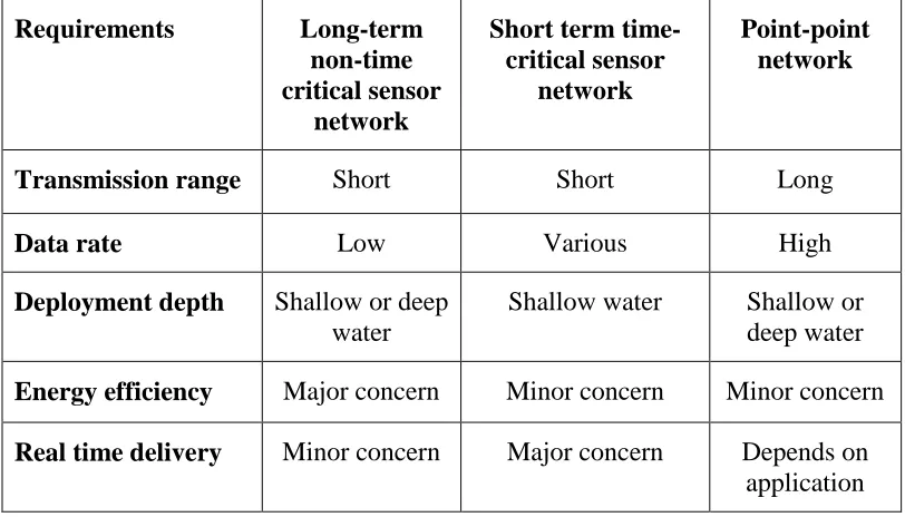
recovery etc. The communication requirement of each type of network is different,
[image:41.595.107.513.350.582.2]which is summarized in the following table 2-1 [2].
Table 2-1 Communication requirements for different underwater networks Requirements Long-term
non-time critical sensor
network
Short term time-critical sensor
network
Point-point network Transmission range Short Short Long
Data rate Low Various High
Deployment depth Shallow or deep water
Shallow water Shallow or deep water
Energy efficiency Major concern Minor concern Minor concern
Real time delivery Minor concern Major concern Depends on application
Long term non-time critical sensor network architecture can be either static or
mobile, depending on the objective of the deployment. On the other hand, a short
term time-critical application normally adopts mobile architecture because of the
nature of application. The focus of this work is to build a non- time critical, long
2.3 Possible options for underwater communication carriers
In free space, the most common communication technology is either wired based on
cooper and fibre optic cable, or wireless which is dominated by radio frequency
communication. But in the ocean environment, none of them are appropriate for
short or medium range applications. Fibre optic cables are installed very deep under
the water to connect different continents, which are very expensive to install, and
cost a lot of money to maintain. On the other hand, radio frequency communication
suffers a significant amount of loss in water (conductivity 0.05mS/m) especially in
sea water (conductivity 4mS/m), so may not be suitable for underwater
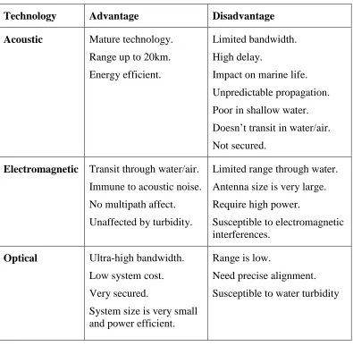
communication. As mentioned earlier, acoustic communications also have their
limitations in specific applications. In this section a detailed description of each of
the technologies has been presented. The Pros and cons of each of the technologies
are summarised in table 2-2 [16].
2.3.1 Research outcome of underwater radio communications
Because of the conducting nature of sea water, radio does not propagate very well
underwater. Attenuation is higher in the high frequencies; therefore most of the
commercial radio equipments, which operate in the MHz and GHz range, cannot be
used underwater. Therefore, the choice is for using a very low frequency radio wave,
which requires a very high power and a large antenna size.
During the mid of last century, radio communication underwater research was
conducted extensively mostly for the military uses. The successful underwater
electromagnetic communications using extremely low frequencies were developed
by US navy and Russian navy for submarine communication. The US system used
Table 2-2 Advantage and disadvantage of different communication carriers underwater
Technology Advantage Disadvantage Acoustic Mature technology.
Range up to 20km. Energy efficient.
Limited bandwidth. High delay.
Impact on marine life. Unpredictable propagation. Poor in shallow water. Doesn’t transit in water/air. Not secured.
Electromagnetic Transit through water/air. Immune to acoustic noise. No multipath affect. Unaffected by turbidity.
Limited range through water. Antenna size is very large. Require high power.
Susceptible to electromagnetic interferences.
Optical Ultra-high bandwidth. Low system cost. Very secured.
System size is very small and power efficient.
Range is low.
Need precise alignment. Susceptible to water turbidity
across the globe to call a specific submarine to come over the surface for radio
communications. To develop a long distance radio based communication system,
Wait proposed a model by which main propagation is established by using a Lateral
EM wave, which travels on the sea surface [17]. To use this technique, a very low
frequency needs to be used for communication to happen. Recently, Al-Shamma’a
and Lucas presented theoretical analysis, simulation, and experimental results to
distance of 100m, at a cost of transmitting power of 100W, which can provide a data
rate of 1Mbps [4] [18] [19]. In their research, they showed that the attenuation is very
high in the first 10m of communication distance, but very low afterwards, which
eventually makes communication possible up to the range of 100m. The reason is
that seawater nearby the antenna acts as a high conductivity because of the intensity
of the electromagnetic field formed by the transmitter antenna. When the distance
increases, it starts to act more as a dielectric. Somaraju and Trumpf also suggested
that large propagation distance is possible at MHz frequency spectrum. According to
their model, conductivity of seawater decreases at small field strengths due to the
hydrogen bonding of water molecules [20]. But, they also failed to prove
experimentally how and why the conductivity of sea water decreases. The signal
strength at a different distance can be found from figure 2-1 [17]. As seen, initially,
signal strength decreases rapidly up to 10m, but eventually it becomes steady. It is
[image:44.595.163.481.464.692.2]also seen that the signal strength remains steady for a long distance even after 90m.
This is actually the noise strength, which has not been considered during the
experiment.
The possibility of underwater radio frequency communication for different
applications is presented in [16]. It has been reported that, the data rate can be up to
10Mbps for fresh water, but hardware implementation for this kind of scenario needs
to be investigated. The design of an underwater sensor network based on 2.4GHz
ISM frequency band has been reported in [21]. In this paper, different aspects of an
underwater radio based sensor network have been discussed. The best modulation
techniques which were observed in experiments are BPSK and QPSK for a
communication distance of 17cm. A static, multi-hop wireless sensor network,
implementing the AODV routing protocol has been reported in [22]. Wireless Fibre
System launched a commercial underwater wireless modem capable of 1Mbps data
transmission at a distance of 1m [23] . Because of the severe attenuation problem in
water, implementing a radio-based communication system may not be a feasible
solution for underwater sensor applications.
2.3.2 Acoustic communication
Acoustic wave is the primary carrier for communications underwater because of the
possibility of longer communication range, due to low absorption of sound waves in
water. Sound travels four times faster at the ocean surface than in air, and
propagation speeds increase with increasing water temperature. The speed of sound
increases 4m/s for an increase of 1 degree centigrade of temperature, and increases
1.4m/s for 1 practical salinity unit (PSU). It has also a relation to the depth of water;
if the water depth increases to 1km, the speed of sound increase by 17m/s. The effect
Figure 2-2 A vertical profile of sound speed as a function of depth [2]
The limitations and challenges of acoustic communications are presented in [24] [25]
[26]. Most important factors which were discussed in those papers are:
Bandwidth is very limited. The highest achievable bandwidth can be
hundreds of kHz for a range of a few metres.
Propagation delay (0.67s/km) is very high, which is in the order of five times
larger compared to radio in free space.
Sound travels in every direction. So it is easy to receive the signals anywhere
even by the unauthorized receiver.
High bit error rate due to multipath propagation caused by inter symbol
interference.
Doppler frequency spread requires a sophisticated receiver design to handle
the inter symbol interferences.
Acoustic communication underwater has a long history, starting from the middle of
group of scientists for military purposes. The research conducted at that time was
mainly to understand ocean phenomena for sound propagation. The acoustic
application underwater was not only limited to communication, it is also has been
used for imaging, navigation, positioning etc. An early stage underwater
communication system was reported by Norman in 1957 [27]. By using 8.087 kHz
single sideband-suppressed carrier communication, distances up to 9000 yards were
achieved. A short range (60m), high data rate (500kbps) communication system was
reported by Kaya and Yauchi in 1989 [28]. The LinkQuest commercial acoustic
modem can support data rates up to 15kbps, for the communication ranges in the
region of few km. In recent years, researchers have been working diligently to
minimize the limitations for better underwater communications using acoustic
waves. For example, a high rate underwater acoustic link for transmitting video was
reported in [29]. An efficient modulation technique and a sophisticated data
compression technique were used to achieve a data rate of 64kbps. Another group
has been trying to use an Orthogonal Frequency Division Multiplexing (OFDM)
based solution to achieve a better link performance [30]. However, obtaining a high
bandwidth using acoustic communication seems unlikely because of the
characteristics of acoustic waves in water.
2.3.3 Underwater optical wireless communication
The limitations of acoustic and radio communications stimulated researchers to see
the possibility of optical wireless especially visible light communication in
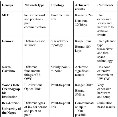
underwater. Until now, the results which have been obtained look very promising.
Some of the underwater optical wireless communication research is summarized in
underwater, which was capable of sending data at Mbps speeds [5]. In his thesis, he
detailed the link budget for underwater optical wireless communication considering
[image:48.595.112.524.236.645.2]the scattering and absorption effects in sea water.
Table 2-3 Summary of different underwater optical wireless communications research
Groups Network type Topology Achieved results
Comments
MIT Sensor network
and pointto -point communication Unidirectional link Range: 2.2m Data rate: 320kbps Used expensive lenses and hardware to achieve results
Genova Diffuse Sensor network
Star network topology
Range : 2m Bitrate:100 kbps Used planner type transceiver and free space technology North Carolina Different fundamental things of U-OWC Mainly point-to-point Achieved significant results Has done extensive research on UW-OW Woods Hole Oceanograp hic Institution Bi-directional Optical link
Point-to-point Range: 200m Bitrate: 5Mbps Very expensive hardware and setup Ben-Gurion University of the Negev Different types of ink for sensor and point-to-point
Point-to-point link
Communicati on up to 100m possible
Simulation based results
Later, his work was advanced further by Simpson ,Cox and Everett to investigate
different issues such as forward error correction, modulation techniques, and
[31] [32] [33]. Cox implemented a Reed-Solomon channel coding in the underwater
optical wireless communication system, and found that the power requirement can be
reduced by 8dB to achieve a bit-error- rate of10 compared to OOK return-to-zero
modulation techniques [34]. Later, Simpson implemented error correction coding for
a 5Mbps link, and tested the system for up to 7.7m [12]. He also built a spatial
diversity system to measure the optical fading in the underwater environment [35].
An unidirectional optical wireless link capable of sending data at 320kbps up to a
distance of 2.2m for underwater sensor networks was presented in [3]. To achieve
this communication distance, a high powered LED array was used, and the link was
only used to upload the sensor data from sensor node to an AUV. The same group
advanced their research to achieve a data rate of 1.2Mbps in the communication
range of 30m [11]. Recently, they reported a bi-directional communication system to
achieve a communication range of 50m [8]. In this paper, a software defined radio
approach was adopted to perform different encoding and decoding techniques. They
used 18, high power LEDs, in an array (each LED was driven at 600mA) at the
transmitter side, and also used an avalanche photodiode at the receiver side to
achieve the distance of 50m. A SNR of 5.1 was determined for a distance of 50m.
Anguita et al also presented a Physical and MAC layer architecture for an
underwater optical wireless sensor network in [26] [15]. The main focus was to build
a diffuse optical wireless communication system capable of interfacing with the
current terrestrial wireless sensor network technologies. They achieved a data rate of
100kbps for a communication distance of 1.8m.
Farr and his group at Woods Hole Oceanographic Research Centre developed a
been proposed by taking account of different link scenarios. This group later reported
a high bandwidth communication link of 5Mbps over a distance of 200m in clean
water using a diffuse optical communication link [36]. Depending on the turbidity of
water, this can be as low as 40m. In their recent system named CORK optical
telemetry system (CORK-OTS), they used both an optical and an acoustic modem
for communications capable of operating up to 10Mbps [37]. They also used both
green and blue light to make the system bidirectional, and used an acoustic modem to
wake up the seafloor installation. Details of the CORK hardware and software were
reported in [38].
Felix also reported a underwater communication system using an IrDA physical layer
with 3W high power LEDs [39]. Hanson proposed a laser based communication link,
which achieved data rate of 1Gbps over a distance of 2m using a water pipe in the
laboratory, and predicted the distance which could be achieved up to 48m in clear
water [9]. A cost-effective underwater optical modem was proposed by Feng to
achieve a communication distance up to 10m [40].
Jaruwatanadilok modelled the underwater optical wireless channel using vector
radiative transfer theory to investigate the multiple scattering and polarization of
light [13]. He calculated the bit error rate for on-off-keying modulation and 4-level
amplitude modulation with different fields of view (FOV). As concluded, the bit
error rate increases according to the distance, and decreases when the FOV is
decreased, because more FOV means more received optical power by the receiver.
Arnon proposed three types of communication links, and analysed the performance
of each type [41]. From his analysis it was shown that the communication
performance decreased rapidly when water absorption increases, but obtaining a high
A basic comparison between different communication systems in underwater is
given in the following table 2-4 [2] [4] [39] [42] .
Table 2-4 Comparison between acoustic, RF and optical medium underwater
Carrier/Features Acoustic Radio Optical wireless
Speed (m/s) 1500 33,333,333 33,333,333
Input power Tens of Watts Watts to Mega-Watts mWatt- Few Watts
Power loss >0.1 dB/m/Hz 28dB/km/100MHz Turbidity
Bandwidth kHz MHz 10-150MHz
Antenna size 0.1m 0.5m 0.1m
Range Km 10m 10-100m
As seen from the table, optical wireless has huge potential compared to other two
carriers in the short and medium communication range. The input power requirement
for optical wireless communication is also lower compared to other two carriers, so it
has been chosen as a communication carrier for the underwater sensor network.
2.4 Attenuation of optical wireless underwater
In spite of having high bandwidth and low power loss, optical wireless also suffers
both from scattering and absorption, resulting in severe attenuation in water.
Behaviour of light in water depends on the water components, so, before designing a
system, one need to understand the propagation phenomena of light in water as it
exhibits differently in different water types. Moreover, system design is affected by
the optical properties of the water. Some of the attenuation factors for optical
The following equation describes the relation between attenuation and
communication distance
Where the position of
respectively, and K is the attenuation coefficient define
Where α is the absorption coefficient which depends on the light wavelength
is the scattering coefficient which mainly depends on wavelength as we
turbidity of water.
Figure
2.4.1 Absorption modelling
Sea water is primarily composed of
as,NaCl MgCl Na So KCl, 2, 2 4,
also occurs due to organic materials like fulvic
shown in figure 2-2. The t
The following equation describes the relation between attenuation and
communication distance [15]
2 1 1 2
2
( )(d )
k d d d
A e
position of transmitter and the receiver are denoted by
K is the attenuation coefficient defined by equation 2
( ) ( )
k
is the absorption coefficient which depends on the light wavelength
is the scattering coefficient which mainly depends on wavelength as we
Figure 2-3 Functional block diagram of total attenuation
Absorption modelling
Sea water is primarily composed of water (H O2 ), but it also has different salts
2 2 4
, , ,
NaCl MgCl Na So KCl, which absorb light at specific wavelengths. Absorption
also occurs due to organic materials like fulvic acid, chlorophyll and
The total absorption coefficient ( )can be calculated from the The following equation describes the relation between attenuation and
(2-1)
the receiver are denoted by d1 and d2
d by equation 2-2
(2-2)
is the absorption coefficient which depends on the light wavelength, and β
is the scattering coefficient which mainly depends on wavelength as well as the
Functional block diagram of total attenuation [5]
, but it also has different salts such
, which absorb light at specific wavelengths. Absorption
chlorophyll and humic acid, as
following equation [5]
( )
a
w( )
a
cl( )
a
f( )
a
h( )
(2-3)Where aw( ) is the absorption coefficient of pure water as a function of wavelength
per metre, acl( ) is the absorption coefficient of chlorophyll, af( ) is the absorption
coefficient of fulvic acid, and ah( ) is the absorption coefficient of humic acid.
Again, each of the absorption coefficients can be defined from [43] [44]. The
absorption coefficient for sea water, aw( ) can be defined from [44]which is given
in equation 2-4
( )
o( )[
c]
awow w o
c
w
a
a
w
(2-4)Where ( )
o w
a =0.0405
, for a water concentration o cw
= 1 3 /mg m and 0≤wc≤15
3 / mg m
Chlorophyll concentration can be expressed as following [41]
0.0602 0
( )
o( )[ ]
ccl c
c
c
a
a
c
(2-5)Where ( )
o c
a is the specific chlorophyll absorption coefficient as a function of
wavelength,
c
c is the total chlorophyll concentration in3 /
mg m , and
0 3
1 /
c
c mg m.
Similarly, absorption coefficient for humic acid and fulvic acid can be expressed by
following equations
[41]:-( )
oh h h h
k
( )
ff
k
o
f f e
a
a
C
(2-7)Where
k
h=0.01105/nm;o h
a
=18.828 2 /m mgis the specific absorption coefficient for
humic acid, and
k
f=0.0189/nm; o fa
=35.959 2 /m mgis the specific absorption
coefficient of fulvic acid. Ch and Cfare the concentration of humic acid and fulvic
acid in mg m/ 3. Now, total absorption can be re-written as follows,
0 0.0602 0 0
0
( ) a ( ) a ( )[
c]
[
kh] [
kf]
w c h h f f
c
C
a
a
C
e
a
C
e
C
(2-8)By considering the attenuation effects mentioned above, it was found that the best
wavelength which propagates in water is in the green-blue region of the visible
spectrum (wavelength 400-550nm), as seen from the figure 2-4 [15]. So, this
wavelength will be considered when designing a transceiver for underwater
[image:54.595.159.481.477.693.2]communication.
2.4.2 Scattering modelling
The scattering coefficient b( ) is defined as the loss of flux due to the re-direction
of photons, which is a combination of the scattering coefficient of pure waterbw( ) ,
small particles ( )
o s
b , and large particles o( )
l
b , as seen in figure 2-2. The total
scattering coefficient can be calculated from the following equation [45],
( ) ( ) o( ) o
w s s l l
b b b C b C (2-9)
Where Cs and Cl are the total concentration of small and large particles in
3 / gm m .
Again, to find each of the coefficients , the equation can be found from [5]
4.322 0.005826 400 ( ) ( )( ) w b m (2-10) 2 1.7 400 ( ) 1.151302( )( )
o s m b g (2-11) 2 0.3 400 ( ) 0.3411( )( )
o l m b g (2-12)
Adding all three equations together gives the total scattering
coefficient:-2
4.322 1.7
2
0.3
0.005826 400 400
( ) ( )( ) 1.151302( )( ) ( )
400
0.3411( )( ) ( )
s l m b C m g m C g (2-13)
Figure 2-5 shows the light scattering behaviour of sea water. It is seen that the
scattering coefficient is at its minimum in the green and blue part of the spectrum,
Figure 2-5 Light scattering coefficient of sea water [46]
Now, considering both the absorption and scattering coefficients, the relationship
between received optical power with respect to transmission distance can be found
from the equation 2-14 ,considering the attenuation [44].
( )LM R T
P Pe
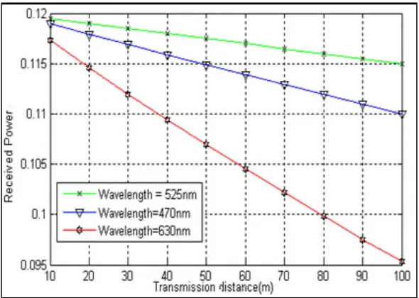
(2-14)Where PR is the received optical power, PT is transmitted optical power, ( )is
attenuation which is wavelength dependent, and LM is the transmission distance. By
keeping all other variables constant in equation 2-14, the relation between
transmission distance and received optical power can be calculated for different
wavelengths, which is shown in figure 2-6.
As absorption and scattering are in minimum level around the blue-green part of the
Figure 2-6 Received optical power vs. communication range
2.5 Issues related to system deign
In this section, some of the system level issues such as photon sources, photon
detectors, and modulation techniques, related to underwater optical wireless
communication will be discussed.
2.5.1 LED or Laser?
The first step to design an optical wireless transmitter starts with the photon source
selection. A Laser, LED or incandescent light can be used as the source, but will
depend on the switching speed, bandwidth, size constrains and power limitation of
the required system. The most widely used photon sources for communications are
LEDs and Lasers, which are compared in table 2-5 [47].
From the table, it is realized that the Laser has minimum divergence, and coherence
compared to an LED, but it has a higher cost and medium life time. In terms of
bandwidth, a laser can operate in the GHz range for high bandwidth applications
life time.
Table 2-5 Comparison between Laser diode and LED Characteristics LED Laser diode
Optical spectral width 25-100nm 0.1-5nm
Modulation bandwidth <200MHz >1GHz
Output beam divergence Wide Narrow
Cost Low High
Life time Long Medium
Reliability High Moderate
Range Low High
Besides all of these characteristics, one should consider the optical power versus
current characteristic of a LED and a laser, which can be found from figure 2-7 [48].
[image:58.595.156.487.470.693.2]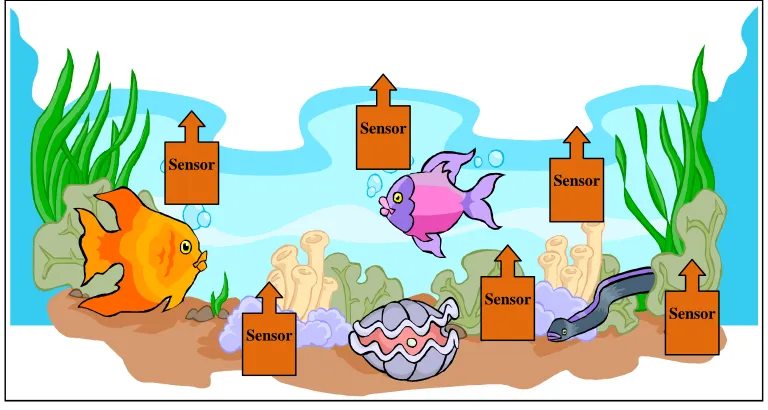
![Figure 2-1 Signal strength as a function of transmitter antenna [17]](https://thumb-us.123doks.com/thumbv2/123dok_us/9600069.463279/44.595.163.481.464.692/figure-signal-strength-function-transmitter-antenna.webp)
![Figure 2-2 A vertical profile of sound speed as a function of depth [2]](https://thumb-us.123doks.com/thumbv2/123dok_us/9600069.463279/46.595.180.462.68.303/figure-vertical-profile-sound-speed-function-depth.webp)
![Figure 2-4 Light absorption in water [15]](https://thumb-us.123doks.com/thumbv2/123dok_us/9600069.463279/54.595.159.481.477.693/figure-light-absorption-in-water.webp)
![Figure 2-5 Light scattering coefficient of sea water [46]](https://thumb-us.123doks.com/thumbv2/123dok_us/9600069.463279/56.595.157.488.70.300/figure-light-scattering-coefficient-sea-water.webp)
![Figure 2-7 Light power versus current characteristics of Laser and LED [45]](https://thumb-us.123doks.com/thumbv2/123dok_us/9600069.463279/58.595.193.447.155.377/figure-light-power-versus-current-characteristics-laser-led.webp)
