Process Modelling of Equal Channel Angular Pressing
for Ultrafine Grained Materials
Hyoung Seop Kim
1, Pham Quang
1, Min Hong Seo
1, Sun Ig Hong
1,
Kyeong Ho Baik
1, Hong Rho Lee
1and Do Minh Nghiep
21Department of Metallurgical Engineering, Chungnam National University, Daejeon 305-764, Korea
2Faculty of Metallurgy and Materials Technology, Hanoi University of Technology, 1 Dai Co Viet, Hanoi, Vietnam
Equal channel angular pressing (ECAP) is a viable forming procedure to extrude material by use of specially designed channel dies without a substantial change in geometry and to make an ultrafine grained material by imposing severe plastic deformation. Because the evolution of microstructures and the mechanical properties of the deformed material are directly related to the amount of plastic deformation, the understanding of the phenomenon associated with strain development is very important in the ECAP process. The plastic deformation behaviour during pressing is governed mainly by die geometry (channel sizes, a channel angle and corner angles), material properties (strength and hardening behaviour) and process variables (temperature, lubrication and deformation speed). There is a need for modelling techniques which may permit a wider study of the effects observed for better process control and the understanding of process related phenomena. In this study, we describe a range of our continuum modelling results of the ECAP process in order to illustrate the modelling applicability. Firstly, the finite element results of ECAP modelling for various geometric factors are described. Secondly, the inhomogeneous deformation due to the hardening property of the material is explained. Lastly, modelling the temperature field coupled with stress as a typical process variable in ECAP is presented.
(Received December 16, 2003; Accepted February 26, 2004)
Keywords: ultrafine grained materials, severe plastic deformation, equal channel angular pressing (ECAP), process modelling, three dimensional analyses
1. Introduction
The evolution of microstructure of metallic materials during plastic deformation has been extensively studied over
the last few decades.1,2) It is generally accepted that if
metallic materials are deformed at room temperature, average subgrain/cell size decreases with strain. Hence, plastic deformation processing can be a possible method for grain refinement of metallic materials. In recent years, severe plastic deformation (SPD) process was developed by Russian scientists as a new method of manufacturing bulk specimens
having ultrafine grained (UFG) microstructure.3–7)The SPD
processed materials show not only the unique physical and mechanical properties inherent in various UFG materials but also a number of advantages over nanostructured materials manufactured by other methods through powder processing. Several methods of SPD processing, such as equal channel
angular pressing (ECAP),3–6)high pressure torsion straining
(HPT),7) accumulated roll bonding (ARB),8) multiple
forg-ing,9) multipass coin-forging,10) repetitive corrugation and
straightening,11) conshearing,12) continuous confined strip
shearing,13) equal channel multi-angular pressing
(EC-MAP)14)etc., have been developed to process bulk materials
with UFG microstructures. Among them, the ECAP process is so far the most viable forming procedure to extrude material by use of specially designed channel dies without a substantial change in geometry and to make an UFG material, see Fig. 1. The properties of the materials are strongly dependent on the plastic deformation behaviour during pressing, which is governed mainly by die geometry (a
channel angle, corner angles15)and perform geometry),
material properties (strength and hardening behaviour),16,17)
and process variables (temperature, lubrication and
defor-mation speed).18) Because the evolution of microstructures
and the mechanical properties of the deformed material are directly related to the history of plastic deformation, the understanding of the phenomenon associated with strain development is very important in the ECAP process.
Since there are so many variables in ECAP, it is clear that there is a need for modelling techniques which may permit a wider study of the effects observed for better process control and the understanding of process related phenomena. In this study, we describe a range of our continuum modelling results of the ECAP process in order to illustrate the modelling applicability. Firstly, the finite element results of ECAP modelling for various geometric factors are described. Secondly, the inhomogeneous deformation due to the hard-ening property of the material is explained. Lastly, modelling temperature as a typical process variable during the ECAP process is presented.
2. ECAP and Finite Element Analysis
Figure 1 shows the principle of ECAP, where two channels
of equal cross-section intersect at an channel angle. With
reference to the workpiece, three perpendicular directions de-noted as pressing direction, width direction and thickness di-rection, respectively, are introduced. The workpiece parts that flow near the inside corner (point A) and the outside cor-ner (point B) of the die will be referred to as the inside part and the outside part, respectively. The deformation during ECAP occurs within the localized zone in the intersecting re-gion of the two channels. The dashed rere-gion (fan-shaped area ABC) in Fig. 1 indicates a ‘main deforming zone’ (MDZ). ECAP involves large shear plastic deformation in the main
deforming zone. Especially, if the die corner angleis 0,
de-formation occurs in the immediate vicinity of the plane,i.e.
the shear plane, lying at the intersection of the two channels. Special Issue on Ultrafine Grained Structures
In a rectangular workpiece, the thickness direction is perpendicular to the width and length directions, so that the strain along the thickness direction is very small compared to
those of the other directions, i.e. plane strain condition
prevails. Therefore, the deformation during the ECAP process of rectangular specimens can be assumed to be two-dimensional in most cases; the finite element mesh system is shown in Fig. 1. In order to investigate the effects of the geometry and material properties on the deformation behaviour of the workpiece during ECAP, isothermal two-dimensional plane-strain finite element method (FEM) simulations for the ECAP process have been carried out
using the commercial finite element codes, DEFORM19)and
ABAQUS.20) The imaginary model material that exhibits
perfect-plastic behavior was used in the calculations, in order to exclude the effect of strain hardening and strain rate on the deformation behavior and to make investigation into a pure
geometric effect. A constant ram speedv¼0:02mms1was
imposed. The coefficient of friction between the die
channel inside and the specimen was assumed to be zero, implying frictionless condition.
On the other hand, there are some situations where variations of quantities in the thickness direction cannot be ignored, such as friction, residual stress and temperature effects. Indeed, friction is the most important process variable which retards the flow of the surface material and results in high shear strain at the bottom region and lower shear strain at the top region of the workpiece. In these cases three dimensional analyses instead of two dimensional ones are necessary. For the investigation of the temperature coupled with stress fields, three dimensional FEM analysis
using the commercial software, MSC.Superforge,21) was
used. The workpiece material used in the calculations was annealed pure copper. Because the stress-strain curve of the high strain range which is necessary for the FEM calculation of the SPD processes cannot be obtained by conventional experimental techniques, the flow curve of the pure copper was theoretically calculated up to large strains of 5 using the
dislocation cell evolution model22) which can describe the
hardening behaviour of dislocation cell-forming crystalline materials at large strains.
3. Results and Discussion
3.1 Geometry effects
There are two controllable parameters in geometric factors in ECAP; i) die geometry which was well investigated both experimentally and theoretically using analytical and numer-ical methods and ii) workpiece geometry.
The most widely controlled geometric parameters are the
channel angle and the corner angle of ECAP dies.
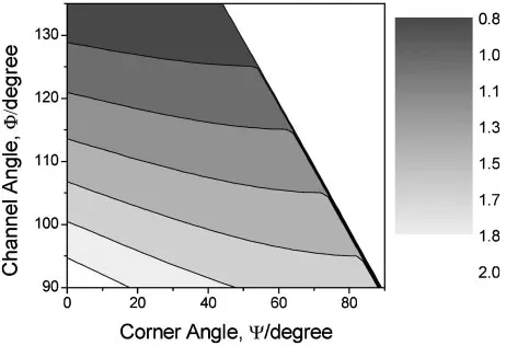
Figure 2 is the calculated equivalent strain"generated in the
workpiece after one pass based on the geometric analysis.23)
"¼ 1ffiffiffi
3
p 2 cot
2 þ
2
þcosec
2 þ
2
: ð1Þ
The effective strain during ECAP can decrease from the maximum of 1.15 to the minimum of 0.907 with changing the
corner angle from ¼0 to ¼90 when the channel
angle is fixed as¼90. The strain is more sensitive to the
corner angle than the channel angle. However, it should be noted that Fig. 2 and eq. (1) represent the average effective strain developed in the workpiece during the ECAP process not the local inhomogeneous strain distributions across the pressing and width directions. It should also be noted that the round die corner not only reduces the overall shear strain but
also intensify the strain inhomogeneity.24)
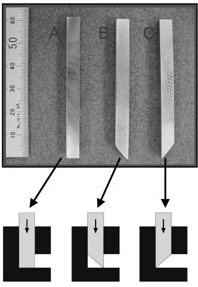
Besides the control of the die geometries, the other effective way of reducing a pressing load and obtaining more homogeneous deformation in ECAP is to modify a perform shape, which is widely used in conventional metal forming
processes, e.g. forging and sheet forming. Figure 3 shows
three preform geometries tried, having different front shapes of workpieces. The predicted effective strain distributions (Fig. 4) corresponding to the three different preforms represent that the type (b) preform generates more uniform strain distribution within the workpiece. Although not shown here, the pressing load is less than the other two types due to the release of the initial transient loading step generated by the front part of the workpiece. The above result implies that there are many possibilities to control the deformation behaviour of materials during ECAP by simply combining the die and workpiece geometries.
Fig. 1 Schematic illustration of the ECAP process and the finite element
[image:2.595.312.543.72.230.2] [image:2.595.51.288.73.221.2]3.2 Material effects
In order to investigate the effects of strain hardening and strain rate sensitivity of materials on the deformation during
ECAP, non-hardening (perfect plastic) materials of n¼0,
strain hardening materials ofn¼0:5, strain rate insensitive
materials ofm¼0, and rate sensitive materials ofm¼0:5
were considered.15) The stress-strain curves for the model
materials are expressed by¼"n""_m, whereis flow stress," is strain,""_is strain rate,nis work hardening exponent andm is strain rate sensitivity. The workpiece material used in the calculations was imaginary non-dimensional model materials
with various strain hardening exponents and strain rate sensitivities. Examples of (nearly) non-hardening materials are peak-aged and overaged Al alloys with high dynamic recovery rate due to easy cross slip in the peak-aged and
overaged matrix and fully pre-strained (e.g. pre-ECAP
experienced) materials which show the saturation of the strength. The example for the strain rate sensitive materials may correspond to ECAP processing of materials at high
temperatures. A constant ram speed v¼1mms1 was
employed.
Figure 5 shows the deformed geometries (flow net) for various materials of different material parameters n and m. In case of (a) the non-hardening and rate insensitive materials
(n¼0andm¼0), the deformed geometry represents almost
ideal and homogeneous behavior within the workpiece. The workpiece flows along the die filling all the inside channel.
On the other hand, in case of (b) the strain hardening and
rate insensitive materials (n¼0:5, m¼0), the corner gap
between the die and the workpiece develops and the center part and the inner part of the workpiece are heavily sheared whereas the outer part appears to be much less sheared. The reason for the formation of die corner gap is due to the difference in developed stress; for the strain hardening materials, the inner part of the workpiece within the deforming zone, which receives more severe deformation, is much harder than the outer part of the deforming zone because of the large hardening exponent. The outer part of the workpiece, which receives lower deformation and there-fore softer than the inner part within the deforming zone, can flow faster to the exit channel and the corner gap is formed. The presence of the less sheared region during ECAP is attributed to the flow path of the workpiece controlled by the die geometry; the outer part of the workpiece with corner gap or in a curved die moves shorter distance than that without corner gap in a sharp-angled die. Therefore, the flow curve Fig. 3 Three different preform shapes.
Fig. 4 Effective strain distributions in three different preform shapes shown in Fig. 3.
(b) n=0.5, m=0
(a) n=0,m=0
(c) n=0, m=0.5
[image:3.595.325.524.67.317.2] [image:3.595.67.268.70.362.2] [image:3.595.48.288.401.605.2]does not make a straight line as in the non-hardening material but draws a curve towards the exit direction in the outer part. That is, the outside surface of the strain hardening workpiece goes through the shorter distance and the bottom surface of the final workpiece of the strain hardening materials would experience the lower shear deformation than that of the non-hardening workpiece. Since the die corner gap reduces the deformation strain especially in the outer part of the workpiece, it produces inhomogeneous deformation and should be avoided if possible.
The strain rate sensitive (m¼0:5) materials in Fig. 5(c)
shows that the outer (bottom after pressed) part of the workpiece experiences more severe deformation and the inner (top after pressed) part of the workpiece shows less shear deformation. The upper channel gap instantly develops upon shearing of the billet from the vertical entrance channel to the horizontal exit channel. The strength near the inner corner increases rapidly due to the high strain rate sensitivity, which would tend to decrease the shear strain. This would result in the formation of the upper channel gap between the billet top and die exit channel, which has the same effect as increasing the die channel angle. The reaction force from the bottom wall would promote the bending of the billet, resulting in the formation of the lower channel gap between the billet bottom and the die.
3.3 Process variable effects
ECAP is conducted not only at a room temperature, but also at elevated temperatures. Although the former is usual because it can fully utilise the grain refining effect and strain hardening results, the latter may be important for difficult-to-work alloys. The temperature change, due to a plastic difficult-to-work release, die chill and frictional heat between the die and the specimen, is important under both cold and hot working conditions, because a temperature rise can induce phase transformation and an alteration in grain structure, especially
in the grain boundary structure.3)These effects, in turn, can
modify the flow stress of the workpiece material as well as other mechanical properties. According to a simple lumped
heat transfer analysis, the temperature rise T of the
workpiece during ECAP can be expressed as follows.20)
T¼ 0:9"þ0:5mð=pffiffiffi3ÞA Vt
CþA Vht
;
ð2Þ
where",,m,,,C,V,A,tand h denote the effective
strain and the effective stress, the friction factor, the relative velocity between the die and the workpiece, the density of the material, its heat capacity, the volume of the calculation
domain (i.e.main deforming zone), the outer surface area of
the domain contacting the die, the dwell time of the domain within the deforming zone and the heat transfer coefficient between the workpiece and the die, respectively.
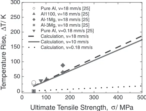
Figure 6 shows a comparison of the calculated and the
experimental25) temperature increases for various materials
with the ultimate tensile strength at various ram speeds,
¼90and¼45using the above heat transfer analysis
eq. (2). The temperature rise increases with the strength of the materials, if the other conditions are the same. The calculated line matches with the experimental temperature rise of Al and
Al alloys well at both fast (18 mms1) and slow
(0.18 mms1) conditions, in that the temperature rise
increases linearly with the ultimate tensile strength. Although the average temperature rises in Al alloys are lower than 100 K, it can be over 150 K for copper which has a flow stress in excess of 400 MPa and the local temperature rise can be even higher than 200 K. This temperature rise can result in a recovery of the defect structure of the grain boundary and a
sharp decrease of the internal stresses in Cu.2)The
temper-ature rise during ECAP can be even more serious for high strength materials such as Al5083 alloys.
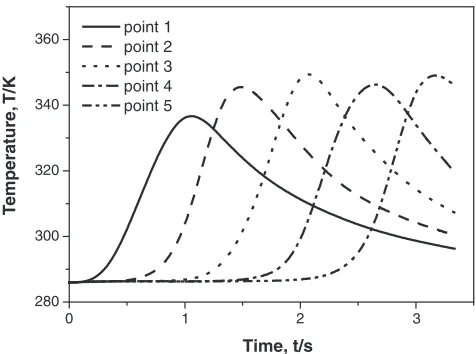
Since the temperature change calculated by eq. (2) is an average value and the temperature in a real workpiece has some distributions (both within the deforming zone and rest of the workpiece), a detailed thermal history cannot be analysed using the lumped approach. Instead, a finite element analysis is necessary for sufficient information on the heat transfer responses of the workpiece during ECAP, consider-ing the material’s nonlinear behaviour, geometric factors, localised deformation and temperature behaviour, conduc-tion and convecconduc-tion terms. For the numerical analysis, two dimensional simulations is not valid because heat flows through the die along the thickness direction. Figure 7 shows the temperature distribution in Al-3Mg predicted by the three dimensional analysis; ¼ ð82:54þ177:46Þ"0:0421 MPa,26)
speed=18 mms1. The temperature rise is about 70 K, which
is comparable to the experimental25)and analytical average
0 100 200 300 400 500
0 50 100 150 200 250 300
Pure Al, v=18 mm/s [25] Al1100, v=18 mm/s [25] Al-1Mg, v=18 mm/s [25] Al-3Mg, v=18 mm/s [25] Pure Al, v=0.18 mm/s [25] Calculation, v=18 mm/s Calculation, v=10 mm/s Calculation, v=0.18 mm/s
Ultimate Tensile Strength, / MPa
T
emper
ature Rise
,
T/ K
∆
σ
Fig. 6 Comparison of the experimental (Ref. 25) and the calculated temperature increases for various materials at¼90and¼45.
[image:4.595.309.544.75.254.2] [image:4.595.306.547.657.764.2]temperature results of Figs. 6 and 7. In Figure 8, the thermal histories at several different points in the workpiece show that not only the heating time but also temperature rise is inhomogeneous; the temperature reaches a higher value in
the rear region (e.g.point 5) than the front region (point 1)
due to conduction heat from the hot front to the cold rear parts during ECAP.
4. Summary
In this study, in order to illustrate the modelling ap-plicability, several results of the continuum approach of the ECAP process were described.
A finite element analysis was carried out and compared to the experimental geometries in order to investigate the effects of the geometric, material and process parameters on the plastic deformation behaviour of the workpiece during the ECAP process. A simple lumped heat transfer analysis, which ignores the temperature inhomogeneity of the work-piece, was done to investigate the temperature rise of the workpiece during ECAP. The temperature rise increases with the strength of the material, the ram speed and the channel angle, and decreases as the density, the heat capacity and the die corner angle increase. A three dimensional numerical investigation reveals that temperature is inhomogeneous in terms of time and temperature rise and the analytical solution is applicable.
Although the macroscopic continuum modelling ap-proaches of ECAP result in successful outputs for a purpose
of the process design, microscopic considerations, e.g.
dislocation, texture, and microstructural evolution, are also necessary, and are underway.
Acknowledgements
This research was performed with the financial support of the Center for Nanostructured Materials Technology under the 21st Century Frontier R&D Program of the Ministry of Science and Technology, Korea.
REFERENCES
1) J. G. Servilano, P. V. Houtte and A. Aernoudt: Prog. Mater. Sci.25
(1980) 69–134.
2) E. Nes: Prog. Mater. Sci.41(1998) 129–193. 3) V. M. Segal: Mater. Sci. Eng.A197(1995) 157–164. 4) R. Z Valiev: Metal Mater. Inter.7(2001) 413–420. 5) I. V. Alexandrov: Metal Mater. Inter.7(2001) 565–571.
6) Y. Fukuda, K. Oh-ishi, Z. Horita and T. G. Langdon: Acta Mater.50
(2002) 1359–1368.
7) H. S. Kim, Y. S. Lee, S. I. Hong, A. A. Tarakanova and I. V. Alexandrov: J. Mater. Proc. Technol.142(2003) 334–337.
8) Y. Saito, H. Utsunimiya, N. Tsuji and T. Sakai: Acta Mater.47(1999) 579–583.
9) A. Belyakov, T. Sakai, H. Miura and R. Kaibyshev: Philos. Mag. Lett.
80(2000) 711–718.
10) A. K. Ghosh and W. Huang: inInvestigation and Application of Severe Plastic Deformation, T. C. Lowe and R. Z. Valiev ed., (Kluwer Academic Publishers, Dordrecht, 2000) p. 29.
11) D. H. Shin, J.-J. Park, Y.-S. Kim and K.-T. Park: Mater. Sci. Eng.A328
(2002) 98–103.
12) Y. Saito, H. Utsunomiya, H. Suzuki and T. Sakai: Scr. Mater.42(2000) 1139–1144.
13) J.-C. Lee, H.-K. Seok, J.-H. Han and Y.-H. Chung: Mater. Res. Bull.36
(2001) 997–1004.
14) H. S. Kim: Mater. Sci. Eng.A328(2002) 317–323. 15) H. S. Kim: J. Mater. Res.17(2002) 172–179.
16) H. S. Kim, M. H. Seo and S. I. Hong: Mater. Sci. Eng.A291(2000) 86– 90.
17) H. S. Kim, S. I. Hong and M. H. Seo: J. Mater. Res.16(2001) 856–864. 18) H. S. Kim: Mater. Trans.42(2001) 536–538.
19) DEFORM: Ver. 5.1, Scientific Forming Technology Corporation, Columbus, OH 1997.
20) Hibbitt, Karlsson & Sorensen Inc.: ABAQUS 5.8. 21) MSC Software Co.: MSC.Superforge.
22) Y. Estrin, L. S. Toth, A. Molinari and Y. Brechet: Acta Mater.46
(1998) 5509–5522.
23) Y. Iwahashi, J. Wang, Z. Horita, M. Nemoto and T. G. Langdon: Scr. Mater.35(1996) 143–146.
24) H. S. Kim: Mater. Sci. Eng.A315(2001) 122–128.
25) D. Yamaguchi, Z. Horita, M. Nemoto and T. G. Langdon: Scr. Mater.
41(1999) 791–796.
26) Q. X. Pei, B. H. Hu, C. Lu and Y. Y. Wang: Scr. Mater.49(2003) 303– 308.
0 2
280 300 320 340 360
T
emperature
, T/K
Time, t/s point 1
point 2 point 3 point 4 point 5
1 3
[image:5.595.50.288.71.248.2]