ISSN Online: 2153-0661 ISSN Print: 2153-0653
DOI: 10.4236/ica.2019.103007 Aug. 12, 2019 107 Intelligent Control and Automation
Obstacle Avoidance Gloves for the Blind Based
on Ultrasonic Sensor
Ruochuan Zhou
The Attached Middle School to Jiangxi Normal University, Nanchang, China
Abstract
Ranging based on the reflection principle of ultrasonic wave propagating in the air has been widely used in modern life, such as car reversing radar, robot automatic obstacle avoidance etc. Aiming at the situation that the blinds have no way to know whether there are obstacles or big safety risks in front of them when they are walking, this paper designed obstacle avoidance gloves for the blinds based on ultrasonic sensors. With Arduino Nano single chip microcomputer as main controller, combined with ultrasonic sensor module, bluetooth module and speaker module, the glove realized the function of ob-stacle detection and alarm. The main working principle is by using the ultra-sonic sensors to transmit and receive ultraultra-sonic, the time difference for transmitting and receiving to detect the distance of obstacles ahead. Besides, by means of voice module output audio signals with different frequency ac-cording to the obstacle distance, the blinds can judge the distance between them to the obstacles based on the sound with different frequencies they heard. In this way, they can make responses in advance to avoid the obstacles ahead and the happening of the risk.
Keywords
The Blind, Avoidance Gloves, Arduino Microcontroller
1. Introduction
It is estimated that the world has 40 million to 45 million binds from the World Health Organization, which haven’t included the low visions. According to the survey, the number of patients with low vision is 3 times the blinds. That means, there are about 140 million low visions from the world, of which 75% or more than 100 million patients can’t restore or improve their eyesight without surgery or diopter correction. And still 25% of low vision patients need low vision care, for example, wear low vision devices and visual rehabilitation instrument etc. [1]. How to cite this paper: Zhou, R.C. (2019)
Obstacle Avoidance Gloves for the Blind Based on Ultrasonic Sensor. Intelligent Control and Automation, 10, 107-117. https://doi.org/10.4236/ica.2019.103007
Received: June 18, 2019 Accepted: August 9, 2019 Published: August 12, 2019
Copyright © 2019 by author(s) and Scientific Research Publishing Inc. This work is licensed under the Creative Commons Attribution-NonCommercial International License (CC BY-NC 4.0). http://creativecommons.org/licenses/by-nc/4.0/
DOI: 10.4236/ica.2019.103007 108 Intelligent Control and Automation Due to the physical defects, blind people have many inconveniences in life and work, among which how to walk safely is the biggest problem. In real life, the blinds usually use the blind rod to detect the obstacle information. But this me-thod is inefficient and also energy consuming. Besides, the blinds need to hold the rod in hand all the time, which brings lots of inconvenience for them. Therefore, there are more and more modernized blind-guiding ways walking into the life of the blinds gradually, such as guiding robots, dogs, electronic glasses and satellite guidance system etc., which have largely enhanced the blinds’ walking ability.
But there are still a lot of limitations in these guiding ways and they are with high cost and very difficult to maintain. To solve the problems, I designed a type of glove that can help the blinds to avoid the obstacle. The glove can use ultra-sonic sensors to measure the distance of obstacles, according to which, the blinds can be warmed to use different audio frequency to avoid the obstacles.
Compared to other obstacle avoidance devices, the Obstacle Avoidance Glove designed by me is more compact, more portable and more practical. With a wide range of obstacle detection and the advantage of convenient wearing, it is able to free the hands of blind people and improve their personal safety while walking.
This article will compare the Obstacle Avoidance Glove with other existing technology and introduce the glove from four main aspects: its design idea, component selection, programming design and structural design.
2. Design Idea and Programming
2.1. Design Idea
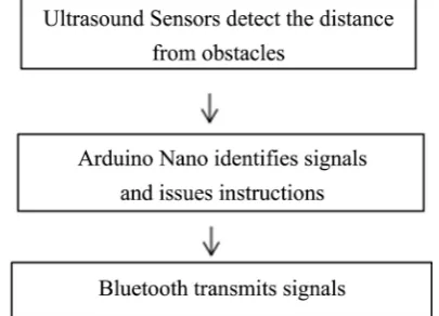
2.1.1. Function Design3 main functions are designed for the blind obstacle avoidance gloves based on Ultrasonic Sensors: 1) The detection for obstacles in front; 2) Different signals transmitted through Bluetooth according to the distance from obstacles; 3) Dif-ferent sounds are prompted according to the distance from obstacles when there are obstacles in front.
2.1.2. Appearance Design
The appearance of obstacle avoidance gloves for the blind based on Ultrasonic Sensor can be divided into two parts: upper computer and lower computer: 1) upper computer combines the sensor with the gloves that we often use in our life; 2) lower computer can be stuck or clipped on the clothes to facilitate the hearing without blocking the external sound.
2.1.3. Interactive Mode
The interaction modes of obstacle avoidance gloves for the blind based on Ul-trasonic Sensor include: 1) measuring the distance between gloves and obstacles by ultrasound; 2) warning gloves users by loudspeakers.
2.1.4. Man-Machine Relation
func-DOI: 10.4236/ica.2019.103007 109 Intelligent Control and Automation tion, it takes the convenience or not, switching freely or not for the blinds to use into account, as well as the need of the blind to be respected and understood psychologically. Compared with the commonly used crutches, this obstacle avoidance glove is simple and portable, which can free the blinds’ hands and fa-cilitate the trip. The machine that hints the sound is pasted or clip in collar etc. that close to the ear place. Only with small volume, the users will be able to hear the sound, which avoided the psychological
2.1.5. Power Supply Mode
The using scene of obstacle avoidance gloves for the blind based on Ultrasonic Sensor includes indoor and outdoor. Considerable power supply methods in-clude DC battery power supply, or DC battery and solar hybrid power supply.
2.2. Component Selection
The components used in the process of making DEMO include Arduino Nano controller, Ultrasonic Sensor, HC-06 Bluetooth module, loudspeaker, Dupont line, etc. The composition diagram of upper computer core hardware function see in Figure 1, and the composition diagram of lower computer core hardware function see in Figure 2.
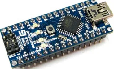
2.2.1. Arduino Nano Controller
Arduino Nano (see in Figure 3) is applied in both upper and lower computers as the control core, mainly due to its open source, low price, small size, can support flex sensor, Bluetooth communication, loudspeaker, etc.
Arduino Nano is a miniature Simple i/o platform based on the open original codes. Compared with the previous USB version of Arduino duemilanove, Ar-duino Nano has a great advantage in volume, and it not only can be used to de-velop electronic products that require running independently and interactive ef-fects, but also to develop electronic products connected with computers, achieve interactive works in the cooperation with software, such as Flash, Processing, Max/Msp, PD, VVVV.
[image:3.595.271.474.557.703.2]Arduino Nano has 12 digital input/output ports D2 - D13; 8 analog input
DOI: 10.4236/ica.2019.103007 110 Intelligent Control and Automation
Figure 2. Composition diagram of lower computer core hardware function.
Figure 3. Arduino Nano hardware.
ports A0 - A7; 1 pair of TTL level serial transceiver ports RX/TX; 6 PWM ports, D3, D5, D6, D9, D10, D11 (see in Figure 4). It applies Atmel Atmega328P-AU MCU which supports USB download and power supply, external 5 V - 12 V DC power supply, 9 V battery power supply and ISP download [2].
2.2.2. Ultrasonic Sensor
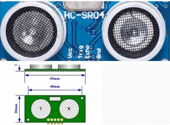
This scheme use the theory that after ultrasonic sensor transmits ultrasonic wave, the ultrasonic wave returns when encountering obstacles. Then the sensor accepts the reflected ultrasonic wave and uses the time difference between transmitting and receiving to detect the distance of obstacles in front The struc-ture diagram of Ultrasonic Sensor see in Figure 5.
The working principle of ultrasonic sensor is as follows: 1) using I/O to trigger ranging and supply high-level signals of at least 10 us; 2) the module automati-cally transmits eight square waves of 40 kHZ to detect the existence of return signals; 3) output a high level through I/O if there is a return signal, the duration of high-level is the time from transmission to return of ultrasound. Testing dis-tance = (duration of high-level*sound speed (340 M/S))/2; Pulse In () is an im-portant function in the application of ultrasonic sensors for detecting the pulse width of high and low levels of the output of pin.
[image:4.595.282.466.268.380.2]DOI: 10.4236/ica.2019.103007 111 Intelligent Control and Automation
[image:5.595.236.512.301.504.2]Figure 4. Arduino Nano hardware circuit diagram.
Figure 5. Structure diagram of ultrasonic sensor.
Table 1. Ultrasound Sensor module and Arduino Nano wire chart.
Ultrasound Sensor echo trig GND VCC
Arduino 2 3 GND 5 V
than 15 degrees; detection distance: 50 px - 11,250 px, high precision up to 5 px; connection mode ports: VCC (power supply), trig (control terminal), echo (re-ceiving terminal), GND (ground) [3]. Ultrasound Sensor module and Arduino Nano wire chart see in Table 1, corresponding Symbols to Distance of Ultra-sound Sensors see in Table 2.
Classical program of Ultrasound Sensors ranging: constintTrigPin = 2;
[image:5.595.210.540.556.591.2]DOI: 10.4236/ica.2019.103007 112 Intelligent Control and Automation float cm;
void setup() {
Serial.begin(9600);
pinMode(TrigPin, OUTPUT); pinMode(EchoPin, INPUT); }
void loop() {
digitalWrite(TrigPin, LOW); //Send a short-time pulse to TrigPin at low and high levels
delayMicroseconds(2); digitalWrite(TrigPin, HIGH); delayMicroseconds(10); digitalWrite(TrigPin, LOW);
cm = pulseIn(EchoPin, HIGH) / 58; //Converting the echo time to cm cm = (int(cm * 100)) / 100; //Keep two decimal places
Serial.print(cm); Serial.print(“cm”);//Serial port output Serial.println(); delay(1000);
}
2.2.3. HC-05 Master-Slave Integrated Bluetooth Module
[image:6.595.206.541.623.655.2]HC-05 master-slave integrated Bluetooth module has a greatest feature that we can ignore the Bluetooth internal communication protocol and directly using Bluetooth as a serial port when the Bluetooth devices paired and connected suc-cessfully. The transmission distance in the open area is about 10 meters. It has the default baud rate at 9600, and the default paired password is 1234. Besides, the default Bluetooth name is HC-05. This work uses two HC-05 Bluetooth modules, one as the transmitting module and the other as the receiving module. The HC-05 Bluetooth module I used has been paired by the teacher. The baud rate function is set as Serial. begin (9600), the function corresponding to the transmitted signal is Serial. println (), and the function corresponding to fetch-ing the signal value is Serial. Read (). The HC-05 Bluetooth module connection between upper and lower is the same. HC-05 Bluetooth module and Arduino Nano wire chart see in Table 3.
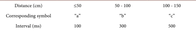
Table 2. Corresponding symbols to distance of ultrasound sensors.
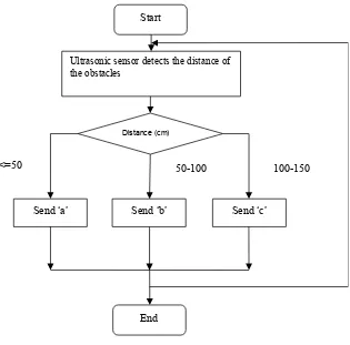
Distance (cm) ≤50 50 - 100 100 - 150
Corresponding Symbols “a” “b” “c”
Table 3. HC-05 bluetooth module and Arduino Nano wire chart.
HC-05 RX TX GND 5 V STATE EN
[image:6.595.206.539.689.731.2]DOI: 10.4236/ica.2019.103007 113 Intelligent Control and Automation 2.2.4. The Loudspeaker Module
The loudspeaker module is equivalent to a passive buzzer. The buzzer is di-vided into active buzzer and passive buzzer. The former has concussion and driving circuit inside, and it produces a sound with power supply, having an advantage of being convenient to use, while the frequency is fixed and there is only one single tone. The latter has controllable sound frequency, which can make the effect of “Do Re Mi Fa So La TiDo (high)”. Common used functions include tone (), and no Tone () [4]. Loudspeaker and Arduino Nano wire chart see in Table 4.
In the composition process, we chose “Do Re Mi Fa So La TiDo (high)”, (see corresponding tone value in Table 5) a total of eight tones.
In this work, tone (294) and tone (330) are selected. The closer the gloves are to the obstacle, the shorter the time between the 2 tones is (see corresponding time intervals in Table 6).
2.3. Programming
We used the Arduino IDE for programming. The Arduino IDE is a software editing environment for Arduino products, mainly used for the editing and de-velopment of Arduino programs. It has the design of opening source circuit dia-gram, the program developing interface which can be free to download and modified according to requirements.
The main function of the upper computer program is to send different signals by Bluetooth after detecting the distance from the obstacle (see in Figure 6), while the main function of the lower computer program is to give out tones with different intervals after receiving the signals from the upper computer (see in Figure 7) [5].
2.4. Structural Design Process
[image:7.595.210.538.667.719.2]Based on ultrasonic sensor, the structure design of the obstacle avoidance glove
Table 4. Loudspeaker and Arduino Nano wire chart.
Loudspeaker Pin1 Pin2
Arduino Nano D7 GND
Table 5. The corresponding tone value to the loudspeaker.
Tone Do Re Me Fa So La Ti Do (high)
Tone Value 294 330 350 393 441 495 556 589
Note: There is no difference between Pin1 and Pin2.
Table 6. Tone interval of loudspeaker corresponds to distance of obstacles.
Distance (cm) ≤50 50 - 100 100 - 150
Corresponding symbol “a” “b” “c”
DOI: 10.4236/ica.2019.103007 114 Intelligent Control and Automation
[image:8.595.223.531.405.704.2]Figure 6. Upper computer program process.
Figure 7. Lower computer program process.
Start
Ultrasonic sensor detects the distance of the obstacles
Distance (cm)
End
100-150 50-100
<=50
Send ‘a’ Send ‘b’ Send ‘c’
Start
Receive Bluetooth signals
Signals
End
c
b
a
Intervals in
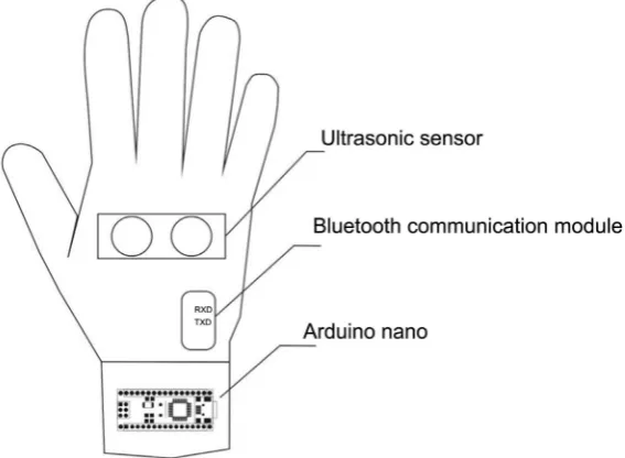
DOI: 10.4236/ica.2019.103007 115 Intelligent Control and Automation for the blinds can be divided into upper computer structure and lower computer structure. The upper computer structure is set with ultrasonic sensor, Bluetooth communication module and Arduino Nano controller (see in Figure 8), while the lower computer structure is set with speakers, Bluetooth module, Arduino Nano controller and switch (see in Figure 9).
3. Testing Results and Innovation Point
[image:9.595.227.511.240.448.2]In the previous practices, scientists normally applied infrared ray to detect ob-stacles. However, in practical application of infrared sensors, there were more interference such as reflected light, which would cause wrong detection and
[image:9.595.241.506.482.707.2]Figure 8. Upper computer structure.
DOI: 10.4236/ica.2019.103007 116 Intelligent Control and Automation trigger false alarm. Some devices try to avoid false detection by emitting a series of consecutive infrared pulses and wait to receive reflected signal. They deter-mine the existence of obstacles by comparing the reflected infrared pulse with the threshold values. Even though such method can lower the false alarm rate to some extent, results of scientific experiments still show that interferences will frequently occur under the existence of stronger reflected light. Different from infrared sensors, ultrasonic sensors are not affected by disturbing factors such as light, smoke and electromagnetic wave. The stable signal of ultrasonic sensor and its affordable cost have opened up broad possibilities for the use of ultra-sonic technology.
The expected goal of this obstacle avoidance glove is to detect whether there is any obstacle in front through the transmission and reception of ultrasonic wave. If yes, the language reminder module will give out warning sounds with different frequency. In the test after debugging, when the glove is 1.5 meters away from the obstacle, the speaker will give out the sound of “doe, reo”, with an interval of 500 mS.
The closer the glove to the obstacle, the shorter the time interval between the two tones will be. When the glove is 50 centimeters away from the obstacle, the time interval will be 100 milliseconds. It can be seen that the obstacle avoidance glove realized the function of the expected setting. When the distance between the glove and the obstacle is different, the lower machine can send out tones with different time intervals, which can be a warning and reminder for the blinds to avoid obstacles.
Main Innovation Points:
1) Large Obstacle Avoidance Distance
Since we use the glove, which has a large space for movement, to detect the distance from the obstacle, the obstacle avoidance range can be wide.
2) Simple, Portable, and Convenient
This product is wearable and can be used with daily gloves for convenient use. 3) Low Price
The product component cost is within 15 dollars and the price can be low.
4. Conclusion
DOI: 10.4236/ica.2019.103007 117 Intelligent Control and Automation
Acknowledgements
Hereby, I would like to express my sincere gratitude to my tutor Huang Qiang, who is the teacher from Beijing Yin Ke Robot Laboratory. He devoted so many time in the process of making the obstacle avoidance and the writing of this pa-per to teach me how to collect literature and also pointed out problems that exist in the programming. Besides, with his guidance, I preliminary learned how to well learn and combine the knowledge from various areas to solve practical problems.
Conflicts of Interest
The author declares no conflicts of interest regarding the publication of this pa-per.
References
[1] Bao, G.H. (2016) The Current Situation and Future Prospect of Large-Character Book Publishing. Disability in China, 7, 30-31.
[2] John, B. (2014) Arduino Workshop. Posts and Telecom Press, Beijing.
[3] Zhang, Q.L. (1993) Principle and Method of Ultrasound Detection. China Univer-sity of Science and Technology Press, Hefei.
[4] Liu, H.S. (2015) Loudspeakers. Speaker Forum, Taipei.