AN EXPERIMENTAL STUDY ON INFLUENCE OF SURFACE CORRUGATIONS TO HEAT TRANSFER
USING DOUBLE PIPE HEAT EXCHANGER
*Dr.
Department of Thermal Power Engineering, VTU PG Studies,
ARTICLE INFO ABSTRACT
The incorporation of surface irregularities on the heat transfer surface is taking its attention because it enhances the thermo
performance enhancement and pressure drop increment comes par
technique. But, in some applications, it is highly appropriate to provide surface roughness where space consideration is more vital to power loss as a result of pressure drop, namely on aerospace industry and nuclear re
surface corrugations to heat transfer using double pipe heat exchanger. The fiction factor and heat transfer parameters are obtained in the turbulent regime and the weight a
compared with the help of thermal performance factor. The experimental data obtained from WILSON PLOT is validated with the data obtained from empirical relations. One smooth tube of 25 mm diameter and two enhanced tubes of same
having surface height, e = 0.3 mm and e = 0.6 mm and pitch, p = 1.3 mm are used. The corrugated tubes are found to be more advantageous than smooth tube for heat transfer applications. The percentage of hea
a tube of e = 0.6 mm, is 90 % to 65 % in the Reynolds number regime of 16700 to 22300.The friction factor for the tube with e = 0.6 mm is found to be greater as compared to
Copyright©2016, Dr. Prakash and Mr. Rajusubedi. This
unrestricted use, distribution, and reproduction in any medium, provided the original work is properly cited.
INTRODUCTION
Heat exchangers are used extensively in many areas like process industries, chemical and petroleum industries, thermal and nuclear power plants, heating ventilation and air conditioning, refrigeration and many other sectors. Since, it occupies a major role in many engineering sectors; the efficiency of its operation is a major concern. The enhancement of effectiveness of heat exchangers permits reduction in size and weight, raises average rate of heat transfer and lowers the difference in temperature betwee fluids. Several heat transfer enhancement techniques are adopted to enhance the thermo-hydraulic behavior of the heat exchanger. The essence of enhancing the heat exchanger’s thermal performance lies in the facts effecting to material, cost and energy savings, have led to the adaption of numerous approaches termed as Heat Transfer Augmentation or Enhancement Technique. The enhancement techniques can be
*Corresponding author: Dr. S. B. Prakash,
Department of Thermal Power Engineering, VTU PG Mysore.
ISSN: 0975-833X
Article History: Received 28th May, 2016
Received in revised form 21st June, 2016
Accepted 18th July, 2016
Published online 20th August,2016
Key words:
Surface corrugations, Double pipe heat exchanger, Heat transfer enhancement, Thermal performance factor, Friction factor,
Pressure drop.
Citation: Dr. S. B. Prakash and Mr. Rajusubedi, 2016. exchanger”, International Journal of Current Research
RESEARCH ARTICLE
AN EXPERIMENTAL STUDY ON INFLUENCE OF SURFACE CORRUGATIONS TO HEAT TRANSFER
USING DOUBLE PIPE HEAT EXCHANGER
Dr. S. B. Prakash and Mr. Raju Subedi
Department of Thermal Power Engineering, VTU PG Studies, Mysore
ABSTRACT
incorporation of surface irregularities on the heat transfer surface is taking its attention because it enhances the thermo- hydraulic characteristics of the heat exchanger. However, the thermal performance enhancement and pressure drop increment comes par
technique. But, in some applications, it is highly appropriate to provide surface roughness where space consideration is more vital to power loss as a result of pressure drop, namely on aerospace industry and nuclear reactors. The objective of this research is to study experimentally on the effect of surface corrugations to heat transfer using double pipe heat exchanger. The fiction factor and heat transfer parameters are obtained in the turbulent regime and the weight a
compared with the help of thermal performance factor. The experimental data obtained from WILSON PLOT is validated with the data obtained from empirical relations. One smooth tube of 25 mm diameter and two enhanced tubes of same diameter with V corrugations on the outer surface having surface height, e = 0.3 mm and e = 0.6 mm and pitch, p = 1.3 mm are used. The corrugated tubes are found to be more advantageous than smooth tube for heat transfer applications. The percentage of heat transfer enhancement for tube with e = 0.3 mm is found to be 68 % to 51% and for a tube of e = 0.6 mm, is 90 % to 65 % in the Reynolds number regime of 16700 to 22300.The friction factor for the tube with e = 0.6 mm is found to be greater as compared to
This is an open access article distributed under the Creative Commons Att use, distribution, and reproduction in any medium, provided the original work is properly cited.
Heat exchangers are used extensively in many areas like process industries, chemical and petroleum industries, thermal and nuclear power plants, heating ventilation and air conditioning, refrigeration and many other sectors. Since, it in many engineering sectors; the efficiency of its operation is a major concern. The enhancement of effectiveness of heat exchangers permits reduction in size and weight, raises average rate of heat transfer and lowers the difference in temperature between the Several heat transfer enhancement techniques are hydraulic behavior of the heat exchanger. The essence of enhancing the heat exchanger’s thermal performance lies in the facts effecting to material, cost y savings, have led to the adaption of numerous
Heat Transfer Augmentation or
. The enhancement techniques can be
Department of Thermal Power Engineering, VTU PG Studies,
categorized into three main types: of tabulators like Inserts and the
surfaces in heat exchanger. In contrast to the augmentation in the heat transfer rate, the heat transfer enha
also escalates largely the friction factor and the required pumping power in the counterpart. However, in some applications, it is highly appropriate to provide surface roughness where space consideration is more vital to power loss as a result of pressure drop. As an example, in case of aerospace applications, the size and weight of the heat exchanger are the significant parameters for design while pumping power comes as secondary parameter. The economic benefit in such applications will
increment in the thermal performance but from the reduction of the material that is achieved by increasing thermal performance or in some aspect, allowing for possibility of using low velocity. In case of nuclear reactors, the main while designing heat exchangers is to reduce the material quantity because of the concern on absorption of more neutrons with increasing material proportion. The enhancement technique occupies its place in such applications in order to enhance thermo
Available online at http://www.journalcra.com
International Journal of Current Research
Vol. 8, Issue, 08, pp.35924-35928, August, 2016
INTERNATIONAL
2016. “An experimental study on influence of surface corrugations to heat transfer using double pipe heat International Journal of Current Research, 8, (08), 35924-35928.
z
AN EXPERIMENTAL STUDY ON INFLUENCE OF SURFACE CORRUGATIONS TO HEAT TRANSFER
Mysore
incorporation of surface irregularities on the heat transfer surface is taking its attention because it hydraulic characteristics of the heat exchanger. However, the thermal performance enhancement and pressure drop increment comes parallel with heat transfer enhancement technique. But, in some applications, it is highly appropriate to provide surface roughness where space consideration is more vital to power loss as a result of pressure drop, namely on aerospace actors. The objective of this research is to study experimentally on the effect of surface corrugations to heat transfer using double pipe heat exchanger. The fiction factor and heat transfer parameters are obtained in the turbulent regime and the weight age of the both factors are compared with the help of thermal performance factor. The experimental data obtained from WILSON PLOT is validated with the data obtained from empirical relations. One smooth tube of 25 diameter with V corrugations on the outer surface having surface height, e = 0.3 mm and e = 0.6 mm and pitch, p = 1.3 mm are used. The corrugated tubes are found to be more advantageous than smooth tube for heat transfer applications. The t transfer enhancement for tube with e = 0.3 mm is found to be 68 % to 51% and for a tube of e = 0.6 mm, is 90 % to 65 % in the Reynolds number regime of 16700 to 22300.The friction factor for the tube with e = 0.6 mm is found to be greater as compared to tube with e = 0.3 mm.
is an open access article distributed under the Creative Commons Attribution License, which permits
categorized into three main types: Use of nanofluid, by the use and the Roughening of heat transfer In contrast to the augmentation in the heat transfer rate, the heat transfer enhancement technique also escalates largely the friction factor and the required pumping power in the counterpart. However, in some applications, it is highly appropriate to provide surface roughness where space consideration is more vital to power result of pressure drop. As an example, in case of aerospace applications, the size and weight of the heat exchanger are the significant parameters for design while pumping power comes as secondary parameter. The economic benefit in such applications will not be arising from the increment in the thermal performance but from the reduction of the material that is achieved by increasing thermal performance or in some aspect, allowing for possibility of using low velocity. In case of nuclear reactors, the main focus while designing heat exchangers is to reduce the material quantity because of the concern on absorption of more neutrons with increasing material proportion. The enhancement technique occupies its place in such applications in order to enhance thermo- hydraulic behavior of the
INTERNATIONAL JOURNAL OF CURRENT RESEARCH
device.(2) The major objective of the present work is to study experimentally the influence of V corrugations made on outside tube surface of inner tube of double pipe heat exchanger to thermo-hydraulic characteristics of heat exchanger. The thermal performance of heat transfer device is evaluated based on heat transfer and friction factor parameters. Also, the experimental data obtained from WILSON PLOT is validated with the data obtained from empirical relations.
Heat Transfer Enhancement Methods
The heat transfer enhancement techniques currently available are generally categorized into three major sets.
Methods requiring power input: Active methods
Methods which does not require power input: Passive Methods
Combination of active and passive Methods: Compound Technique
Roughness Elements Classification
Roughness is defined as the small scale projections or protrusions compared to smooth physical plane surface. basis of the physical ground, the artificial roughness can be categorized as:
1. Integral Roughness 2. Superimposed roughness
The integral roughness elements are integrated with the primary heat transfer surface. The integral roughness indicates the roughness elements are the integral part of the main surface. The superimposed roughness elements can be considered as turbulators. Such roughness elements are not integrated to the heat transfer surface. The different type of inserts like wire inserts, coil inserts are superimposed roughness elements
Experimental setup
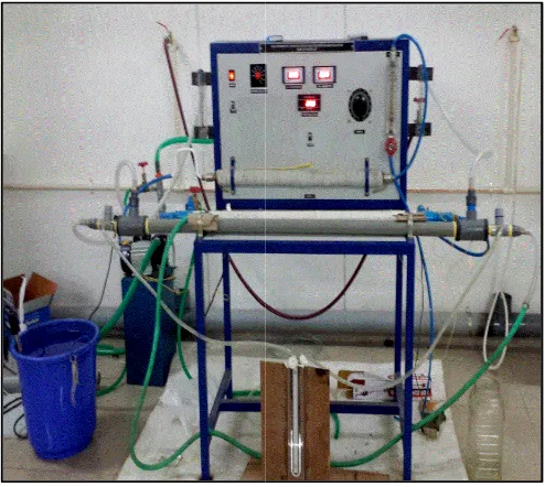
The Figure 1 illuminates the experimental setup with its planlayout. The setup consists of double pipe heat exchanger,
Rotameter, centrifugal pump, U-Tube manometer,
thermocouple, Temperature display unit, overhead tank which is used for supplying cold water, hot water tank with submersion heater and a control unit.
The experimental test section which is one of the components of the experimental setup is a double pipe heat exchanger arranged in a countercurrent flow configuration. It consisted of inner tube made up of Aluminium and outer tube made of CPVC. Total of 3 tubes were tested; one smooth tube for the reference motive and the remaining two were enhanced tubes. The heat transfer fluid used was the normal hard water with the cold fluid being in the annulus side and the hot fluid in the tube side. Two calibrated Rotameters were used in the setup, placed in the cold fluid and the hot fluid side respectively with the flow measuring range of 20-1080 LPH. The cold fluid was drawn from the overhead tank with the assistance of gravity.
35925 Dr. Prakash and Mr. Raju Subedi, An experimental study on influence of surface corrugations to heat transfer using double pip
The major objective of the present work is to study experimentally the influence of V corrugations made on outside tube surface of inner tube of double pipe heat hydraulic characteristics of heat xchanger. The thermal performance of heat transfer device is evaluated based on heat transfer and friction factor parameters. Also, the experimental data obtained from WILSON PLOT is validated with the data obtained from empirical relations.
The heat transfer enhancement techniques currently available are generally categorized into three major sets.
Methods requiring power input: Active methods Methods which does not require power input: Passive
Combination of active and passive Methods:
Roughness is defined as the small scale projections or protrusions compared to smooth physical plane surface. On the basis of the physical ground, the artificial roughness can be
elements are integrated with the primary heat transfer surface. The integral roughness indicates ness elements are the integral part of the main elements can be considered as turbulators. Such roughness elements are not integrated to the heat transfer surface. The different type of serts are superimposed
1 illuminates the experimental setup with its planlayout. The setup consists of double pipe heat exchanger,
Tube manometer,
display unit, overhead tank which is used for supplying cold water, hot water tank with
The experimental test section which is one of the components of the experimental setup is a double pipe heat exchanger n a countercurrent flow configuration. It consisted of inner tube made up of Aluminium and outer tube made of CPVC. Total of 3 tubes were tested; one smooth tube for the reference motive and the remaining two were enhanced tubes. ed was the normal hard water with the cold fluid being in the annulus side and the hot fluid in the tube side. Two calibrated Rotameters were used in the setup, placed in the cold fluid and the hot fluid side respectively with the The cold fluid was drawn from the overhead tank with the assistance of gravity.
[image:2.595.307.560.87.316.2]The cold water was available with the temperature range: 300C.
Fig. 1. Schematic layout of the Experimental Setup
Fig. 2. Test Experimental Setup
The hot water was supplied from the hot water tank at an approximated temperature of 50
centrifugal pump of rating 0.5 kW. The hot water was produced with the help of the submersion Nichrome heater of rating 1.5 kW. The bypass va
discharge of the pump for controlling the flow rate and the bypass was re-circulated to the hot water tank. The U manometer was placed in order to measure the pressure drop in the cold fluid and the hot fluid side and the t
tapings were made at the inlet and outlet section of the heat exchanger and were connected to the U
mercury as a Manometric fluid. temperature measuring range:0
number, one at the hot water tank, one for atmospheric
Dr. Prakash and Mr. Raju Subedi, An experimental study on influence of surface corrugations to heat transfer using double pip
The cold water was available with the temperature range:
28-Schematic layout of the Experimental Setup
Test Experimental Setup
The hot water was supplied from the hot water tank at an approximated temperature of 50-52 0C with the help of the centrifugal pump of rating 0.5 kW. The hot water was produced with the help of the submersion Nichrome heater of The bypass valve was facilitated at the discharge of the pump for controlling the flow rate and the circulated to the hot water tank. The U- Tube manometer was placed in order to measure the pressure drop in the cold fluid and the hot fluid side and the two pressure tapings were made at the inlet and outlet section of the heat exchanger and were connected to the U-Tube manometer with mercury as a Manometric fluid. K Type Thermocouple with a temperature measuring range:0-2000C, were placed six in e at the hot water tank, one for atmospheric
[image:2.595.310.557.347.568.2]temperature, two at the inlet and outlet of the hot fluid side and the remaining two at the inlet and outlet of the cold fluid side. The Figure 2 shows the experimental setup used for the heat transfer analysis.
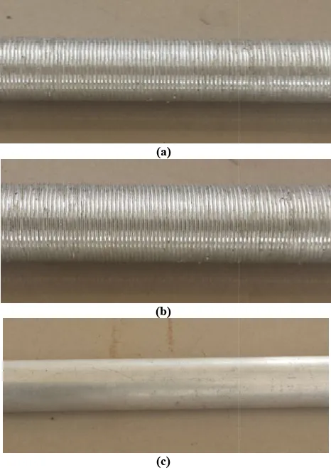
Heat exchanger and Tube geometry
Heat exchanger: Double pipe heat Exchanger (40 mm * 25 mm) and length = 1.5 m
Smooth tube: OD = 25 mm, Length= 1.5 mm
First enhanced tube :Thread depth= 0.3 mm with pitch =1.3 mm
Second enhanced tube: Thread depth= 0.6 mm with pitch = 1.3 mm
(a)
(b)
(c)
Fig. 3. (a) Enhanced tube with Thread depth= 0.3 mm with pitch =1.3 mm (b)Enhanced tube with Thread depth= 0.6 mm with pitch = 1.3 mm (c) Smooth tube with OD = 25 mm, Length= 1.5 mm
Equations used
I. Calculation of Friction Factor:
a.Using Drew, Koo and McAdams within ± 5% 2013)
= 0.0014 + . . , for smooth pipe
√ = 1.8 (
.
+ (
. )
. )
, for rough pipe (Haaland, 1983)
35926 International Journal of Current Research,
temperature, two at the inlet and outlet of the hot fluid side and the remaining two at the inlet and outlet of the cold fluid side. 2 shows the experimental setup used for the heat
Heat exchanger: Double pipe heat Exchanger (40 mm *
Smooth tube: OD = 25 mm, Length= 1.5 mm
First enhanced tube :Thread depth= 0.3 mm with pitch
Second enhanced tube: Thread depth= 0.6 mm with
(a) Enhanced tube with Thread depth= 0.3 mm with pitch =1.3 mm (b)Enhanced tube with Thread depth= 0.6 mm with pitch = 1.3 mm (c) Smooth tube with OD = 25 mm, Length= 1.5
Using Drew, Koo and McAdams within ± 5% (Drew et al.,
, for rough pipe (Haaland,
b.Darcy Equation
= 2
II. Energy Balance Equation
a.
Q = m*Cp*(T1-T2)III. Heat Transfer Calculations
For, Re ≥ 10000, 0.7 < Pr < 16700, L/D ≥ 60, Sieder Tate Equation (Kothandaraman and
a.
= 0.027 . .b.
For Fully Developed flow, DittusFor,2500< Re < 1.25*10^6 , L/D > 60 and 0.6 < Pr < 100
= 0.023
For fluids increasing its temperature, n = 0.4 For fluids decreasing its temperature, n = 0.3
c.
=d.
=( () ( ) )( )
IV. Thermal Performance factor
= ( )
RESULTS AND DISCUSSION
[image:3.595.47.280.232.563.2]The important results drawn from the nature of the experimental data are discussed
Fig. 4. Q vs. Re of cold fluid
International Journal of Current Research, Vol. 08, Issue, 08, pp.35924-35928, August, 2016
Energy Balance Equation
III. Heat Transfer Calculations
≥ 10000, 0.7 < Pr < 16700, L/D ≥ 60, Sieder Tate and Subramanyam, 2015)
( ) .
For Fully Developed flow, Dittus- Boelter equation is used 1.25*10^6 , L/D > 60 and 0.6 < Pr < 100
.
For fluids increasing its temperature, n = 0.4 For fluids decreasing its temperature, n = 0.3
factor
RESULTS AND DISCUSSION
The important results drawn from the nature of the experimental data are discussed
Q vs. Re of cold fluid
[image:3.595.306.561.542.728.2]Fig. 5. h exp vs. h the or for smooth tube
Fig. 6. h vs. Re of cold fluid
Fig. 7. he /hs vs. Re of cold fluid
[image:4.595.39.558.56.535.2]Fig. 8. Pressure drop vs. Flow of cold fluid
Fig. 9. fe/f vs. Frictional Re of cold fluid
Fig. 10. Thermal Performance factor vs. Re
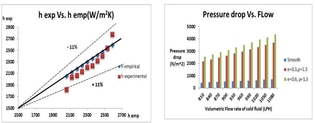
[image:4.595.35.558.269.740.2]It can be noted from Figure 4 that the average heat transfer rate for smooth tube is increased from 2.8 kW to 3.6 kW, in the range of Re, 16700 to 22300 while for the tube with e = 0.3 mm consisted of heat transfer increment rate from 4.1 kW to 4.57 kW and for a tube with e = 0.6 mm, from 4.4 kW to 4.7 kW. It can be seen from figure 5 for a smooth tube that the range of h emp is from 2060 to 2592 W/m2K while h exp came to
be in the range of 1819 to 2773 W/m2K. The theoretical and experimental values are obtained in the range of ± 11% error. The figure 6 showed that the heat transfer coefficient for enhanced tube with e =0.3 mm is increased from 68 % to 51 % in a Reynolds number range of 16700 to 22300 and the maximum enhancement occurred with lowest Re. For a tube with e = 0.6 mm, the heat transfer coefficient is increased from 90 % to 65 % in a given range of Re. The increment in convective coefficient of heat transfer is because of the enhanced thermal and fluid transport properties induced by the thinning of the boundary layer caused by the surface roughness. The thinning of boundary layer is more as the roughness value increases and resulted in more increment in heat transfer coefficient. The Figure 7 illuminated that the enhancement ratio for a given roughness is decreased with increasing Reynolds number. The reason for drastic increment in the pressure drop for enhanced tube as shown in figure 8 is because of high increment in the friction factor caused by the roughness on the surface. The rough tube enhanced the turbulence in the flow with introduction of the secondary viscosity coefficient and induces more shear force and hence more friction factor which leads to the considerably higher pressure drop compared to smooth tube. The figure 10 showed firstly that the thermal performance factor is increased with increase in roughness value (ηc2>ηc1) and second, the thermal
performance factor is declined with rise in Reynolds number. The maximum thermal performance factor for corrugated tube with e = 0.3 mm is 0.981 and for a tube with e = 0.6 mm, the maximum value is 1.047. The mean thermal performance factor is 9.3 % higher for corrugated tube with e = 0. 6 mm as compared to tube with e= 0.3 mm.
Conclusion
The prime objective of this research was to study the influence of surface corrugations to heat transfer in a double pipe heat exchanger. Following conclusions are derived from the experimental study and the nature of the data obtained.
In a bigger picture, the corrugated tubes are found to be more advantageous than smooth tube for heat transfer applications.
The variation of empirical and experimental data for smooth tube is found to be in the range of ± 11 %.
The convective heat transfer coefficient enhancement for tube with e = 0.3 mm is found to be in the range of 68 % to 51 % and for tube with e = 0.6 mm is found to be in the range of 90 % to 65 % in a range of Reynolds number of 16700 to 22300.
The enhancement in the heat transfer coefficient at low value of Reynolds number is found to be greater. Thus, the heat transfer enhancement ratio is decreased with increasing Reynolds number.
The friction factor is found to be increased with increasing the roughness value but tends to remain constant at higher regime of Reynolds number.
The important conclusion that we can make is that, the energy saving is more for corrugated tubes at low value of Reynolds number
REFERENCES
Bhattacharyya, A. 1964. “Heat Transfer and Pressure drop with Rough Surfaces”, Aktiebolaget Atomenergi, Stockholm, Sweden.
Drew, Koo, and McAdams, 2013. “Process heat Transfer”, Donald Q. Kern, 25th Reprint, page no. 53.
Gaurav Johar and Virendra Hasda, “ Experimental Studies on heat transfer augmentation using modified reduced width twisted tapes (RWTT) as inserts for the tube side flow of liquids”, NIT Rourkela, 2010
Hamed Sadighi Dijazi,amad Jafarmadar, FarokhMobadersani, 2015. “Experimental tudies on heat transfer and pressure drop characteristics for new arrangements of corrugated tubes in a double pipe heat exchanger”, International Journal of Thermal Sciences, 96, 211- 220
Kothandaraman, CP. and S Subramanyam, 2015. “Heat and Mass Transfer Data hand book, New Age International Publishers, page no. 126.