Abstract — In recent years, the Global Positioning System (GPS) has been commonly employed for outdoor positioning and location tracking. On the other hand, there has also been growing interest in developing indoor location tracking systems.
Advancements in radio frequency identification (RFID) technology make it a promising technology for use in indoor location tracking systems. In this paper, we present an RFID-based location tracking system using a peer-to-peer (P2P) network architecture, which can provide flexibility for system implementation and cost-effectiveness for system maintenance.
The proposed system employs active RFID technology to estimate the location of users/objects, and ZigBee to build a P2P network for communication purposes. It can be used for various purposes, such as asset management and customer relationship management.
Index Terms — RFID, Location Tracking, Peer-to-Peer Networks
I. INTRODUCTION
n recent years, there has been considerable interest in developing location or position tracking systems.
Generally, such systems can be classified into indoor and outdoor systems. For outdoor location tracking, the Global Positioning System (GPS) is the most commonly used technology. Funded and developed by the Department of Defense (DoD) of the United States, it has been in use since the mid-1990s [1]. Essentially, in GPS, a receiver uses satellite signals to estimate its position (e.g., for navigation purposes [2]). Cellular communications offer an alternative outdoor location tracking solution [3]. Here, the communications signals transmitted between the base stations and the mobile terminals are used to estimate the location of a mobile terminal. However, GPS and cellular communications cannot be employed in an indoor environment and may not work well in urban areas because signal reception can be affected by tall buildings.
For indoor location tracking systems, Wi-Fi and RFID are two major technologies that can be used. Both can be employed to perform location estimation using such methods as Received Signal Strength Indicator (RSSI), Time of Arrival (TOA), Time Difference of Arrival (TDOA), and fingerprint methods [4][5][6]. The popularity of WLANs has led to WLANs becoming common communications
Manuscript received January 8, 2014.
Felix C. P. Hui and Henry C. B. Chan are with the Department of Computing, The Hong Kong Polytechnic University, Hong Kong (e-mail:
{cscphui, cshchan}@comp.polyu.edu.hk).
S. H. Fung is with Hong Kong RFID Limited (e-mail:
This project was supported by the Innovation and Technology Fund of the Hong Kong Special Administrative Region Government and by Hong Kong RFID Limited.
infrastructure in commercial buildings and indoor environments such as shopping malls, coffee shops, hotels, and airports. Existing WLANs infrastructure make it possible for indoor location tracking systems to be developed without the installation of additional networking equipment [7]. For this reason, Wi-Fi-based location tracking techniques have become commonly used solutions for indoor environments.
However, a Wi-Fi-based solution requires not only Wi-Fi-based infrastructure but also Wi-Fi-supported user devices, which may be costly under certain circumstances.
For example, a Wi-Fi-based solution may not be cost-effective for tracking the location of objects or the locations of a large number of users without Wi-Fi devices.
RFID can provide an alternative solution to the use of Wi-Fi. In recent years, RFID has been widely used in different areas [8] such as retailing [9] and logistics [10][11].
Due to the growing demand for RFID for various indoor applications (e.g., for supporting a warehouse system [12]), it is of interest to study the use of RFID for indoor location tracking. Compared with Wi-Fi devices, RFID tags are cheaper and can provide similar functions more cost effectively. However, unlike Wi-Fi, where the infrastructure is often pre-installed, an RFID-based location tracking system requires additional equipment. This paper seeks to address this issue.
Employing a Peer-to-Peer (P2P) network would be a desirable solution to making an RFID-based tracking system more practical and effective. A P2P network is basically a distributed network, which operates through collaboration among the network nodes [13]. In a P2P network, computers or devices can interact with each other in a direct and flexible manner. Unlike traditional networking or client/server approaches, communications can be conducted and information can be exchanged on an ad hoc basis [13]. For instance, Guntella is a popular file sharing system that operates using a P2P network [14][15]. In the proposed P2P RFID-based location tracking system, all readers will represent a node and be connected to at least one other reader to form a P2P network. With the use of the ZigBee protocol, the network can be formed easily and new nodes can be joined using a simple procedure. Data can be easily exchanged. In summary, a P2P-based system facilitates system installation, technical maintenance, and future expansion.
The rest of this paper is organized as follows. In Section II, an overview of the active RFID readers/tags and the communications protocol for the system is given. In Section III, the system architecture of the RFID-based location tracking system is presented. In Section IV the location tracking mechanism is presented. Section V concludes the
RFID-based Location Tracking System Using a Peer-to-Peer Network Architecture
Felix C. P. Hui, Henry C. B. Chan, and S. H. Fung
I
paper and contains an outline of possible future work.
II. ACTIVE RFID&COMMUNICATIONS PROTOCOLS A. Overview
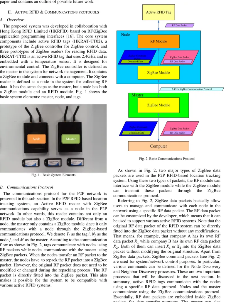
The proposed system was developed in collaboration with Hong Kong RFID Limited (HKRFID) based on RF/ZigBee application programming interfaces [16]. The core system components include active RFID tags (HKRAT-TT02), a prototype of the ZigBee controller for ZigBee control, and three prototypes of ZigBee readers for reading RFID data.
HKRAT-TT02 is an active RFID tag that uses 2.4GHz and is embedded with a temperature sensor. It is designed for environmental control. The ZigBee controller is defined as the master in the system for network management. It contains a ZigBee module and connects with a computer. The ZigBee reader is defined as a node in the system for collecting RF data. It has the same shape as the master, but a node has both a ZigBee module and an RFID module. Fig. 1 shows the basic system elements: master, node, and tags.
Fig. 1. Basic System Elements
B. Communications Protocol
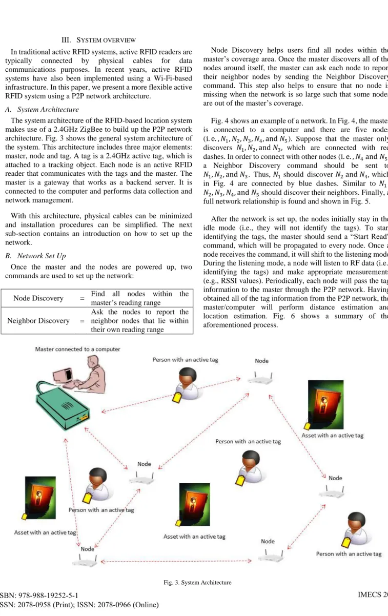
The communications protocol for the P2P network is presented in this sub-section. In the P2P RFID-based location tracking system, an Active RFID reader with ZigBee communications capability serves as a node in the P2P network. In other words, this reader contains not only an RFID module but also a ZigBee module. Different from a node, the master only contains a ZigBee module since it only communicates with a node through the ZigBee-based communications protocol. We denote as the tag i, as the node j, and as the master. According to the communication flow as shown in Fig. 2, tags communicate with nodes using RF packets while nodes communicate with the master using ZigBee packets. When the nodes transfer an RF packet to the master, the nodes have to repack the RF packet into a ZigBee packet. However, the original RF packet does not need to be modified or changed during the repacking process. The RF packet is directly fitted into the ZigBee packet. This also makes it possible for the system to be compatible with various active RFID systems.
Active RFID Tag
RF Module
ZigBee Module
ZigBee Module
Computer Master
RF Data Packet
ZigBee Data Packet RF Data Packet
ZigBee Data Packet RF Data Packet
2.4GHz ZigBee Communication Protocol
Node
ZigBee Command Packet Command Data
ZigBee Command Packet Command Data
Fig. 2. Basic Communications Protocol
As shown in Fig. 2, two major types of ZigBee data packets are used in the P2P RFID-based location tracking system. Using these two types of packets, the RF module can interface with the ZigBee module while the ZigBee module can transmit these packets through the ZigBee communications protocol.
Referring to Fig. 2, ZigBee data packets basically allow users to manage and communicate with each node in the network using a specific RF data packet. The RF data packet can be customized by the developer, which means that it can be used to support various active RFID systems. Note that the original RF data packet of the RFID system can be directly fitted into the ZigBee data packet without any modifications.
That means, for example, that company A has its own RF data packet while company B has its own RF data packet . Both of them can insert or into the ZigBee data packet without modifying the original structure. Apart from ZigBee data packets, ZigBee command packets (see Fig. 2) are used for system/network control purposes. In particular, various commands can be defined for the Node Discovery and Neighbor Discovery processes. These are two important processes that will be discussed in the next section. In summary, active RFID tags communicate with the nodes using a specific RF data protocol. Nodes and the master communicate using the ZigBee communications protocol.
Essentially, RF data packets are embedded inside ZigBee packets for data transfer purposes. The master can also control the nodes through various commands, which are conveyed through the P2P network using ZigBee packets.
Master Node
III. SYSTEM OVERVIEW
In traditional active RFID systems, active RFID readers are typically connected by physical cables for data communications purposes. In recent years, active RFID systems have also been implemented using a Wi-Fi-based infrastructure. In this paper, we present a more flexible active RFID system using a P2P network architecture.
A. System Architecture
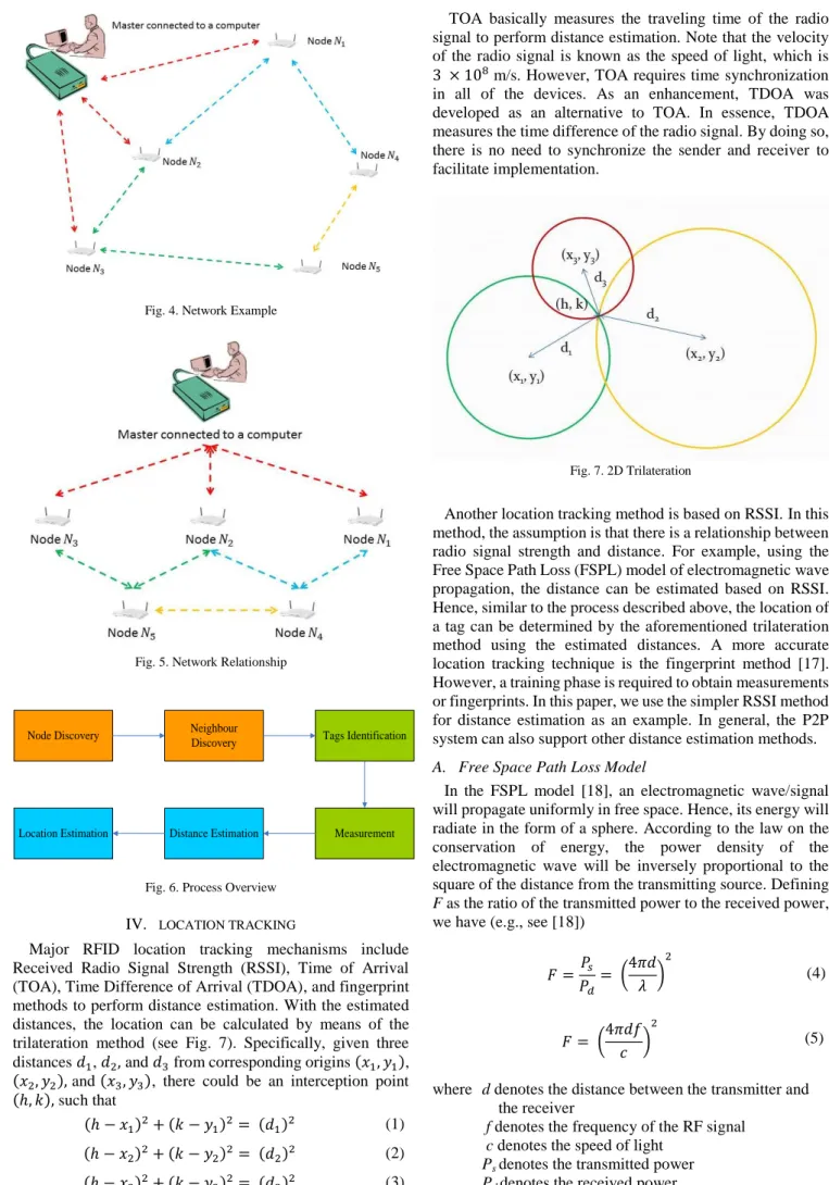
The system architecture of the RFID-based location system makes use of a 2.4GHz ZigBee to build up the P2P network architecture. Fig. 3 shows the general system architecture of the system. This architecture includes three major elements:
master, node and tag. A tag is a 2.4GHz active tag, which is attached to a tracking object. Each node is an active RFID reader that communicates with the tags and the master. The master is a gateway that works as a backend server. It is connected to the computer and performs data collection and network management.
With this architecture, physical cables can be minimized and installation procedures can be simplified. The next sub-section contains an introduction on how to set up the network.
B. Network Set Up
Once the master and the nodes are powered up, two commands are used to set up the network:
Node Discovery = Find all nodes within the master’s reading range
Neighbor Discovery =
Ask the nodes to report the neighbor nodes that lie within their own reading range
Node Discovery helps users find all nodes within the master’s coverage area. Once the master discovers all of the nodes around itself, the master can ask each node to report their neighbor nodes by sending the Neighbor Discovery command. This step also helps to ensure that no node is missing when the network is so large such that some nodes are out of the master’s coverage.
Fig. 4 shows an example of a network. In Fig. 4, the master is connected to a computer and there are five nodes ( ). Suppose that the master only discovers which are connected with red dashes. In order to connect with other nodes ( ), a Neighbor Discovery command should be sent to
. Thus, should discover which in Fig. 4 are connected by blue dashes. Similar to , should discover their neighbors. Finally, a full network relationship is found and shown in Fig. 5.
After the network is set up, the nodes initially stay in the idle mode (i.e., they will not identify the tags). To start identifying the tags, the master should send a “Start Read”
command, which will be propagated to every node. Once a node receives the command, it will shift to the listening mode.
During the listening mode, a node will listen to RF data (i.e., identifying the tags) and make appropriate measurements (e.g., RSSI values). Periodically, each node will pass the tag information to the master through the P2P network. Having obtained all of the tag information from the P2P network, the master/computer will perform distance estimation and location estimation. Fig. 6 shows a summary of the aforementioned process.
Fig. 4. Network Example
Fig. 5. Network Relationship
Node Discovery Neighbour
Discovery Tags Identification
Measurement Distance Estimation
Location Estimation
Fig. 6. Process Overview IV. LOCATION TRACKING
Major RFID location tracking mechanisms include Received Radio Signal Strength (RSSI), Time of Arrival (TOA), Time Difference of Arrival (TDOA), and fingerprint methods to perform distance estimation. With the estimated distances, the location can be calculated by means of the trilateration method (see Fig. 7). Specifically, given three distances , and from corresponding origins ( ), ( ) and ( ), there could be an interception point ( ) such that
( ) ( ) ( ) (1) ( ) ( ) ( ) (2) ( ) ( ) ( ) (3)
TOA basically measures the traveling time of the radio signal to perform distance estimation. Note that the velocity of the radio signal is known as the speed of light, which is m/s. However, TOA requires time synchronization in all of the devices. As an enhancement, TDOA was developed as an alternative to TOA. In essence, TDOA measures the time difference of the radio signal. By doing so, there is no need to synchronize the sender and receiver to facilitate implementation.
Fig. 7. 2D Trilateration
Another location tracking method is based on RSSI. In this method, the assumption is that there is a relationship between radio signal strength and distance. For example, using the Free Space Path Loss (FSPL) model of electromagnetic wave propagation, the distance can be estimated based on RSSI.
Hence, similar to the process described above, the location of a tag can be determined by the aforementioned trilateration method using the estimated distances. A more accurate location tracking technique is the fingerprint method [17].
However, a training phase is required to obtain measurements or fingerprints. In this paper, we use the simpler RSSI method for distance estimation as an example. In general, the P2P system can also support other distance estimation methods.
A. Free Space Path Loss Model
In the FSPL model [18], an electromagnetic wave/signal will propagate uniformly in free space. Hence, its energy will radiate in the form of a sphere. According to the law on the conservation of energy, the power density of the electromagnetic wave will be inversely proportional to the square of the distance from the transmitting source. Defining F as the ratio of the transmitted power to the received power, we have (e.g., see [18])
(
) (4)
(
) (5)
where d denotes the distance between the transmitter and the receiver
f denotes the frequency of the RF signal c denotes the speed of light
Ps denotes the transmitted power Pd denotes the received power.
Also, we have
( ) ( ) (6) ( ) ( ) ( ) (7)
From (5), we have
(
) (8)
( ) ( ) (9)
Substituting (7) into (9), we have
( ) (10) where
( ) ( ) ( ) (11)
This means that, theoretically, RSSI should have a linear relationship with log(d). Note that, in practice, we also need to take into consideration other factors (e.g., antenna gain).
B. Experiments
In order to test whether RSSI has a linear relationship with log(d), several indoor and outdoor experiments were conducted. The results are compared and shown in Fig. 8 (i.e., RSSI is plotted against log(d)). The results show that (13) can provide a reasonable relationship between RSSI and log(d):
(12)
where α and β are constants.
By determining the values of α and β, the distance can be estimated. After obtaining the estimated distances from three readers, the location of a tag can be estimated by applying the trilateration method.
Fig. 8. RSSI Value Comparison
V. CONCLUSIONS AND FUTURE WORK
In conclusion, we have presented an RFID-based location tracking system using a peer-to-peer network architecture.
The proposed system makes use of active RFID technology for identifying and tracking people and objects. A P2P network with RFID readers is formed based on ZigBee. In other words, the readers communicate using the 2.4GHz ZigBee protocol. We have designed and tested the communications protocol for the proposed system to support Node Discovery and Neighbor Discovery. By using a P2P network architecture, system setup and maintenance can be greatly facilitated. Furthermore, new readers can be added to the system in a flexible manner. We have also studied the use of RSSI for location estimation purposes. Ongoing work is being conducted to enhance the proposed system, with a particular focus on devising more accurate location estimation methods.
REFERENCES
[1] G. Xu, GPS: Theory, Algorithms and Applications, Springer, 2007.
[2] R. Bajaj, S. L. Ranaweera, and D. P. Agrawal, “GPS: location-tracking technology”, IEEE Computer, vol. 35, no. 4, pp. 92 – 94, Mar. 2002.
[3] P. Chen, “A cellular based mobile location tracking system”, Proc.
IEEE Vehicular Technology Conference, 1999.
[4] S. A. Golden and S. S. Bateman, “Sensor measurements for Wi-Fi location with emphasis on time-of-arrival ranging”, IEEE Transactions on Mobile Computing, vol. 6, pp. 1185 – 1198, Oct. 2007.
[5] S. Mazuelas, A. Bahillo, R. M. Lorenzo, P. Fernandez, F. A. Lago, E.
Garcia, J. Blas, and E. J. Abril, “Robust indoor positioning provided by real-time RSSI values in unmodified WLAN networks”, IEEE Journal on Selected Topics in Signal Processing, vol. 3, pp. 821 – 831, Oct.
2009.
[6] A. K. M. M. Hossain, H. N. Van, Y. Jin, and W. Soh, “Indoor localization using multiple wireless technologies”, Proc. IEEE International Conference on Mobile Adhoc and Sensor System, 2007.
[7] N. Chang, R. Rashidzadeh, and M. Ahmadi, “Robust indoor positioning using differential Wi-Fi access points”, IEEE Transactions on Consumer Electronics, vol. 56, no. 3, pp. 1860 – 1867, Aug. 2010.
[8] S. Shepard, RFID: Radio Frequency Identification, McGraw Hill Professional, 2005.
[9] S. F. Wamba, L. A. Lefebvre, Y. Bendavid, and E. Lefebvre,
“Exploring the impact of RFID technology and the EPC network on mobile B2B eCommerce: A case study in the retail industry”, International Journal of Production Economics, vol. 112, pp. 614 – 629, Apr. 2008.
[10] R. Oh and J. Park, “A development of active monitoring system for intelligent RFID logistics processing environment”, Proc.
International Conference on Advanced Language Processing and Web Information Technology, July 2008.
[11] H. K. H. Chow, K. L. Choy, W. B. Lee, and K. C. Lau, “Design of a RFID case-based resource management system for warehouse operations”, Expert Systems with Applications, vol. 30, pp. 561 – 576, May 2006.
[12] S. H. Fung, C. F. Cheung, W. B. Lee, and S. K. Kwok, “A virtual warehouse system for production logistics”, Production Planning &
Control, vol. 16, no. 6, 597 – 607, Sept. 2005.
[13] L. L. Peterson and B. S. Davie, Computer Networks: A System Approach, Morgan Kaufmann, 2003.
[14] M. Ripeanu, “Peer-to-peer architecture case study: Gnutella network”, Proc. First International Conference on Peer-to-Peer Computing, Aug.
2001.
[15] R. Matei, A. Iamnitchi, and P. Foster, “Mapping the Gnutella network”, IEEE Internet Computing, vol. 6, pp. 50 – 57, Feb. 2002.
[16] “XBee® /XBee-PRO® ZB RF Modules”, Website:
http://ftp1.digi.com/support/documentation/90000976_P.pdf
[17] R. Zekavat and R. M. Buehrer, Handbook of Position Location: Theory, Practice and Advances, John Wiley and Sons, 2011.
[18] “Free-space path loss”, Website:
http://en.wikipedia.org/wiki/Free-space_path_loss.
y = -20x - 40.046
y = -23.643x - 65.088
y = -25.973x - 58.576
-90 -80 -70 -60 -50 -40 -30
0 0.2 0.4 0.6 0.8
RSSI (dBm)
Log(distance)