University of Warwick institutional repository: http://go.warwick.ac.uk/wrap
A Thesis Submitted for the Degree of EngD at the University of Warwick
http://go.warwick.ac.uk/wrap/36357
This thesis is made available online and is protected by original copyright.
Please scroll down to view the document itself.
Application and Development of Fieldbus
Executive Summary
by
Richard Stuart Hadley Piggin
Submitted in partial requirement for the Degree of
Doctor of Engineering
E
I—.
WAR9CK
Department of Engineering University of Warwick
Abstract
Confusion over fieldbus technology by manufacturers and customers alike is due to a number of factors. The goal of a single global fieldbus standard, the subsequent development of European standards, the recognition of a number of emerging de facto standards and the continued international standardisation of fieldbus technology is still perplexing potential fieldbus users. The initial low supply and demand for suitable devices and compatible controller interfaces, the high cost of control systems and inertia caused by resistance to change have all contributed to the slow adoption of fieldbus technology by industry. The variable quality of fieldbus documentation has not assisted the acceptance of this new technology.
An overview of industrial control systems, fieldbus technology, present and future trends is given. The quantifiable benefits of fieldbus are identified in the assessment of fieldbus applications and guidance on the appropriate criteria for the evaluation and selection of fieldbus are presented. End users can use this and network planning to establish the viability, suitability and benefits of various control system architectures and configurations prior to implementation.
The enhancements to a network configuration tool are shown to aid control system programming and the provision of comprehensive diagnostics. A guide to fieldbus documentation enables manufacturers to produce clear, consistent fieldbus documentation. The safety-related features for a machine safety fieldbus are also determined for an existing network technology.
Demonstrators have been produced to show the novel use of fieldbus technology in different areas. Transitory connections are utilised to reduce complexity and increase functionality. A machine safety fieldbus is evaluated in the first installation of a fully networked control application. Interoperability of devices from many different manufacturers and the benefits of fieldbus are proven.
Experience gained during the membership of the British Standards Institution AMT/7 Committee identified the impact of standards and legislation on fieldbus implementation and highlighted the flawed use of standards to promote fieldbus technology. The Committee prepared a Guide to the evaluation of fieldbus specifications, a forthcoming publication by the BSI.
Acknowledgements
I would like to thank Richard McLaughlin and Dr. Ken Young for their guidance during this project.
I wish to extend my appreciation to the many people at Rockwell Automation who have provided
assistance, especially Keiran Coultan, Francis Monk and Peter Townsend.
Thank you Jackie for your support, endurance, patience and marvellous sense of humour, when it
must have been very necessary.
Finally, thank you to my family, especially Gillian.
R.S.H.Piggin
Declaration
The work presented has been undertaken by myself unless otherwise acknowledged. Apart from the
submission for the Degree of Master of Science in Engineering Business Management, this work has
not been previously submitted for any other award.
© Richard Stuart Hadley Piggin
October 1999
Contents
Introduction...I
1 .1 Fieldbus ...1
1 .1 Control system & fieldbus history ...1
1 .2 Industrial market situation...3
1 .3 Portfolio overview...6
2 Fieldbus overview ... 7
2 .1 Control systems ...7
2 .2 The fieldbus solution...8
2 .3 Strategic benefits of fieldbus... 9
2 .4 The automation industry & fieldbus ...10
2 .5 Case studies - principal benefits achieved ...10
3 Selection of fieldbUS technology & network planning ...ii
3 .1 The fieldbus market ...11
3 .2 Selection of fleldbuS technology...12
3 .3 Network planning & installation cost comparison ...13
3 .4 Configuration tool enhancement...15
3 .5 Manual design...16
4 Fieldbus application case studies & benefits ... 18
4 .1 Background...18
4 .2 Automotive...18
4 .3 Building materials...19
4.4 Computer assembly...20
4 .5 Packaging ...21
4 .6 Paper production...21
4 .7 Water treatment...22
4 .8 Application ...23
5 Fieldbus demonstrator case study ...24
5 .1 Overview...24
5.2 System architecture ...25
5.3 System Integration...27
5.4 Research engineer contribution...29
5.5 Further work...30
5.6 Innovation & application...30
6 Transitory connections utilising fieldbus... 32
6.1 Fieldbus benefits...32
6.2 Controller Area Network over slip rings...33
6.3 Robot flexible couplings and links...33
6.4 Transitory connections using CAN ...33
6.5 Tool pallet quick connect ...34
6.6 Robot tool changer...35
6.7 Innovation & application...36
7 Safetyrelatedfieldbus ... 37
7.1 Introduction ...37
7.2 Safety fieldbus benefits...38
7.3 Safety...39
7.4 Reliability...39
7.5 Legislation & standards...39
7.6 DeviceNet safety fieldbus ...42
7.7 Safety fieldbus implementation...42
7.8 Further work...44
7.9 Innovation and application ... 44
8 Fieldbus standards and committee work...46
8.1 Overview...46
8.2 Fieldbus standards...46
8.3 British Standards Institution work ...49
8.4 Fieldbus standards...49
9.1
Control system architecture...51
9.2
Integration of manufacturing & business systems...51
9.3
Real-time Ethernet...52
9.4
Machine safety fieldbus ...53
10
Conclusion ...
10.1
Fieldbus selection & planning...
10.2
Application case studies ...54
10.3
Fieldbus demonstrator...54
10.4
Transitory fieldbus connection ...55
10.5
Safety fieldbus ...55
10.6
Fieldbus standards...55
11
Glossary... 56
12
Bibliography...57
13
References ... 58
vi
List of Figures
Figure1 Control technology development ...2
Figure2 Barriers to fieldbus implementation...3
Figure3 Adoption of technology cycle diagram ...5
Figure4 Machine control...7
Figure5 Plant communications heirarchy...8
Figure6 Control & network strategy...8
Figure7 Network positioning of leading open fieldbus ...11
Figure 8 Worldwide shipment shares of distributed/remote I/O...12
Figure 9 Fieldbus demonstrator ...24
Figure10 Demonstrator architecture ...26
Figure11 SALVO cell showing the tooling, conveyor and robots...34
Figure 12 Tool changer showing DeviceNet trunk and drop cabling ...35
Figure 13 Safetybus p installation architecture ...43
List of Tables
Table1 Industrial input/output devices...7
Table2 Network characteristics...g
Table3 Principal standards affecting safety-related fieldbus...40
Table4 Error prevention mechanisms recommended by BIA ...41
Table 5 Safety Integrity Levels for safety-related EIE/PE system operating in high demand or
continuousmode...42
R.S.H.Piggin
Introduction
I Introduction
1.1 Fieldbus
Fieldbus is defined by the International Electrotechnical Commission (IEC) as a "generic term
for a serial, digital communications network, supporting multiple measurement, control and
actuation devices on a shared medium." 1 The term fieldbus is commonly used in the
automation industry to describe non-proprietary or open network technologies. The fieldbus
industry is still very young, with the initial take up of the technology being slow, particularly in
the UK. 2'3 Recently, rapid growth has been reported by fieldbus associations and in market
surveys.4'5 Fieldbus networks are increasingly replacing the traditional hardwiring of
automation systems, with manufacturers using fieldbus as a core strategy in the provision of
seamless control system integration. 6' 7 Fieldbus technology presents many strategic benefits,
however with a low rate of adoption in the UK, these opportunities are being missed. The
project objectives were to increase and develop the appropriate use of fieldbus technology.
1.1
Control system & fieldbus history
Prior to 1969 traditional machine control was based on Relay Control Systems. 8 The high
cost of modification and revision to control systems for each new model prompted General
Motors to specify solid state (semiconductor) control systems. This was to provide the same
functionality as Relay Control Systems providing logic capability improved reliability and
expansion.
Other requirements included competitive pricing with relay panels, ease of programming
(hence relay ladder logic), modularity (to facilitate fault-finding and repair) and compactness.
The controller also had to be rugged, operating in an industrial environment and easily
interfaced with existing input and output devices. The final consideration was maintenance,
to be undertaken by the same electricians looking after the current systems.
Introduction
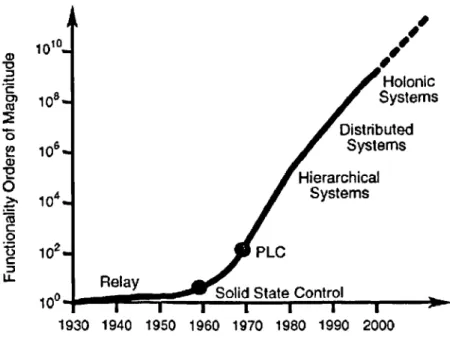
field wiring still providing electrical inputs and outputs to and from the control panel
respectively (Figure 1).
1010
108
I
Systems7
HolonlcW6l
Distributed Systems
104] Systems
102 PLC
Relay
A°- UIIU O(dLt '.j j I ILl UI
lv
I
I
I I I1930 1940 1950 1960 1970 1980 1990 2000
Source: Allen Bradley
Figure 1 Control technology development
Shortly afterwards the first device network was introduced by Cutler-Hammer called Directrol,
but the features were too advanced for the PLCs and PCs available at the time and the
network disappeared in the early 1980s. The intervening period saw most control system
manufacturers produce proprietary remote I/O networking solutions, replacing the hardwiring
of sensors, actuators and other I/O devices back to local PLCs or remote PLC I/O racks. In
addition to these, there are specialist networks for many applications, including motion
control, welding and hazardous environments.
In the 1990s control systems manufacturers were compelled by market pressure to open
previously proprietary networks (e.g. AS-i, ControlNet, DeviceNet, Interbus, Profibus, & SDS).
The degree of openness can be distinguished by the number of supporting manufacturers
and the technology association management (some are still closely managed by the
companies that developed the technology). Since the mid 1980s there have been efforts to
produce an international universal fieldbus standard, that was originally more suited to the
a,
V
C 0)
0
a,
0
>'
C 0
C
LL
Introduction
process industry (recent developments indicate this standard may combine a number of yet
undecided incompatible technologies). Differences between technology consortia caused a
proliferation of standards activity in the mid 1990s to market open fieldbus technologies and
gain competitive advantage. This resulted in three European standards, two comprising a
number of incompatible technologies, with more European and International standards in
progress.9
1.2 Industrial market situation
At the outset of this research there was very low market penetration of fieldbus technology in
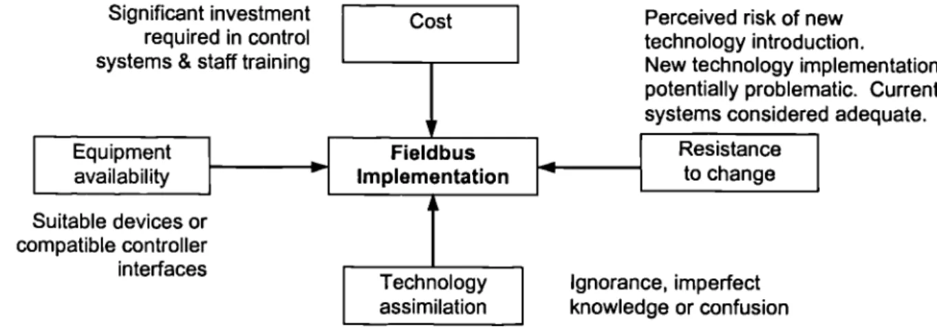
the UK. Barriers have slowed the implementation of fieldbus technology (Figure 2).
Significant investment required in control systems & staff training
Cost Perceived risk of new
technology introduction.
New technology implementation
I
potentially problematic. Currentsystems considered adequate.
Equipment availability
Suitable devices or compatible controller interfaces
Fieldbus
Implementation
Technology assimilation
Resistance to change
Ignorance, imperfect knowledge or confusion
Figure 2 Barriers to fieldbus implementation
The investment required when changing or upgrading control systems has influenced buying
decisions, particularly where small companies are concerned. Many of the early large-scale
fieldbus installations have been in large companies that can afford to devote significant
resources to automation. 1 ° Companies with a stable or falling demand are unlikely to make
additional investment, unless it can reverse the anticipated market demand.
Availability of fieldbus equipment has been a problem during the introduction of fieldbus.
Introduction
education by customers. Interface development is still viewed by some as cost that may not
be recouped in the foreseeable future, but the only means to keep important customers.
Limited equipment availability affected users in two ways, in the suitability of interfaces to
existing equipment and the need for specific field devices for applications. This then created
either a time lag in implementation or additional cost issues. Fieldbus continues to be viewed
as a remote WO replacement, as opposed to a means of transparent integration of intelligent
devices.
The market was ignorant of fieldbus, in an effort to inform UK industry the DTI produced a
fieldbus guide, unfortunately biased more towards process industries than manufacturing.11
The Department of Trade and Industry (DTI) is currently sponsoring the FACES (Fieldbus
Awareness Campaign and Exploitation Support) programme to promote awareness and
benefits of the technology. DTI have also partially funded the forthcoming publication of a
guide to evaluation of fieldbus, produced by the British Standards Institution (BSI).12
Confusion and misunderstanding are still common amongst those that are at least aware of
fieldbus. The number of different technologies available confuses potential users, but
manufacturers and fieldbus organisations are marketing the strengths and the almost
universal suitability of each technology to any potential application.
This situation has been exacerbated by the strategy of some producers to seek
standard isation of their technology to ensure market penetration through the competitive
advantage obtained. As a result, the implementation of fieldbus has been slow. Many
potential users are waiting, anticipating market consolidation with fewer technologies or
hoping for a universal fieldbus solution.
Inertia can also be attributed to a resistance to change, exhibited by the unwillingness of
some control engineers to use fieldbus. Reasons given demonstrate perceived risk in the
application of new technology, which may be unproven, even in a particular industrial sector.
This view seeks to lessen and delay the 'learning curve' where the implementation could be
Introduction
time-consuming, painful and expensive. 13 The painful aspect of fieldbus continues to be felt
by engineers in the selection of a particular fieldbus in an environment where there are many
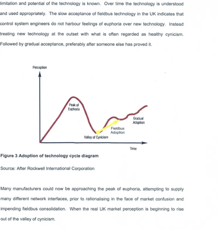
potential solutions and little educated advice. Figure 3 shows the adoption cycle of new
technology, sometimes beginning with a state of euphoria, where the technology is regarded
as a panacea. This is followed by a negative reaction (rapidly becoming cynicism) as the
limitation and potential of the technology is known. Over time the technology is understood
and used appropriately. The slow acceptance of fieldbus technology in the UK indicates that
control system engineers do not harbour feelings of euphoria over new technology. Instead
treating new technology at the outset with what is often regarded as healthy cynicism.
Followed by gradual acceptance, preferably after someone else has proved it.
Perc6ption
Time
Figure 3 Adoption of technology cycle diagram
Source: After Rockwell International Corporation
Many manufacturers could now be approaching the peak of euphoria, attempting to supply
many different network interfaces, prior to rationalising in the face of market confusion and
impending fieldbus consolidation. When the real UK market perception is beginning to rise
Introduction
1.3 Portfolio overview
In order to address these problems a number of projects have been performed covering
different aspects of fieldbus implementation. Unbiased guidance on selection and the
application of fieldbus technology is given, and new applications of fieldbus technology are
developed.
Projects presented are:
1. Selection of fieldbus technology, network planning, configuration tool and device manual
enhancement.
2. Equipment integrated into fieldbus demonstrator to show interoperability of devices,
features and benefits of fieldbus technology.
3. Application case studies illustrating quantifiable benefits and advantages of fieldbus.
4. Transitory fieldbus connection for robot tool changer and safety devices.
5. Impact of fieldbus standards and legislation, participation in the British Standards
Institution (BSI) Advanced Manufacturing Technology (AMT/7) Committee (fieldbus) &
preparation of BSI fieldbus guide.
6. First installation of an integrated safety fieldbus solution and research into additional
safety related features required for a fieldbus to meet machine safety standards.
These projects are discussed following an overview of fieldbus technology.
Fieldbus Oveiview
2 Fieldbus overview
2.1 Control systems
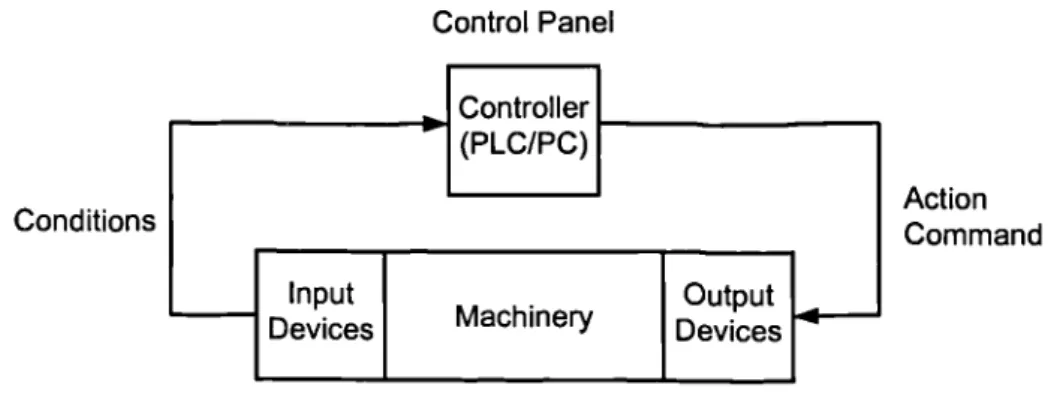
A programmable logic controller (PLC) or personnel computer (PC) may be used to control a
process (Figure 4).
Conditions
Control Panel
I
Controller ____________ (PLC/PC)1Input
I
I
OutputDevices
I
MachineryI
DevicesAction Command
Source: After Allen-Bradley
Figure 4 Machine control
Traditionally, the input devices and output devices are hardwired to the controller. Typical
industrial input/output devices are shown in Table 1.
Input Devices
• Limit, proximity, pressure, and temperature
switches • Push buttons • Logic
• Digital data
• Analogue (flow, pressure, speed, temperature, etc.)
Output Devices
• Solenoids • Motor starters • Indicators • Alarms • Logic • Digital data
• Analogue (flow, pressure, speed, temperature, etc.)
Source: After Allen-Bradley
Table I Industrial inputloutput devices
A fieldbus is an alternative to individually wiring inputs and outputs, however other data may
also be passed between the controller and field devices. These may include device
Fieldbus Overiiew
2.2 The fieldbus solution
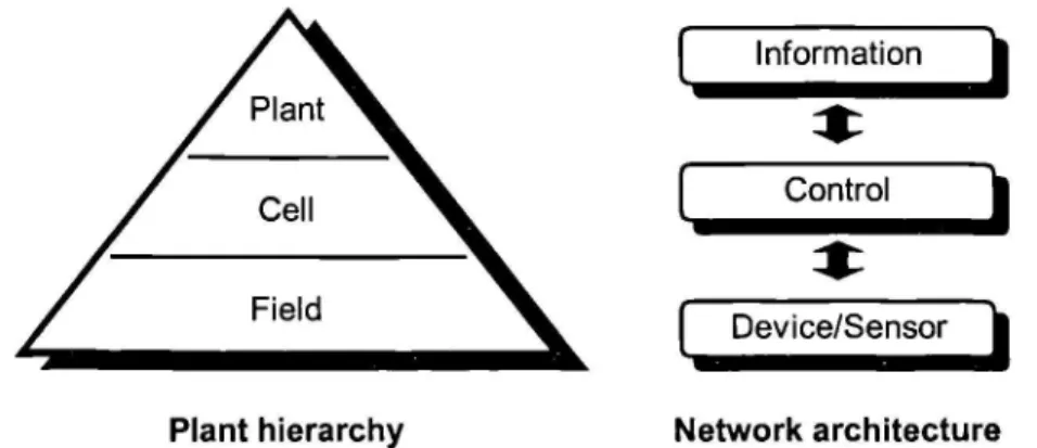
Automation manufacturers offer integrated plant control systems that correspond to the
automation pyramid paradigm, with fieldbus networks providing the communication strategy
enabling total and seamless integration (Figure 5).
Plant hierarchy
Source: Siemens & Allen-Bradley
Figure 5 Plant communications heirarchy
[ Information
Control
1
Device/Sensor
Network architecture
This communication architecture may be utilised as the control system strategy, the example
shown in Figure 6, is the network architecture used in the Structurally Advanced Light Weight
Vehicle Objective (SALVO) project at the Warwick Manufacturing Group.
0000
Ethernet______ ____________
- -- DeviceNet -i.._.
Safetybusp
A
Safety
L
SAFETY - Light Curtains, Laser Scanners, Remote I/O - Door Interlocks, Emergency Stops,
Robot controllers
Figure 6 Control & network strategy
Fieidbus Oveiview
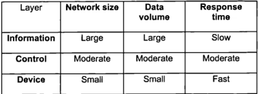
The distinct requirements of each layer necessitate the provision of different fieldbus
technologies (Table 2). The characteristics of the different networks balance the need for real
time control (time critical), with little data, against a less timely response (non-time critical)
with large quantities of data. The control layer can support a mixture of time critical and
non-time critical data, such as I/O data, operator displays, motion control, and the downloading of
device configuration data and program data (e.g. robots & PLC5).
Layer Network size Data Response
volume time
Information Large Large Slow
Control Moderate Moderate Moderate
Device Small Small Fast
Source: Soo Beng Khoh14
Table 2 Network characteristics
2.3
Strategic benefits of fieldbus
According to Fieldbus standard lEG 61158 (approaching completion) fieldbus users can
expect the following strategic benefits:15
• reduction in capital cost to build or expand plant;
• faster commissioning or refits of plant;
• "more product with less material";
• improved, closer, more flexible and repeatable control;
• greater precision and accuracy;
• reduced maintenance and running costs;
• global practice and sourcing;
Fieldbus Oveiview
2.4
The automation industry & fieldbus
The high cost of automation is illustrated by the £6.5 million investment in a new assembly
line by Ford at the Halewood Transmission Plant. The gearbox assembly line was previously
traditionally hardwired and complex, with 200 cable terminations in a typical control cabinet.
This made the line difficult to set up, maintain and change, where the competitive
environment necessitated increased capacity and better quality with reduced cost.16
The Ford manufacturing engineer stated that the complexity of the old control system caused
problems to be time consuming to locate and expensive to rectify. These concerns led to the
implementation of fieldbus technology, enabling improved responsiveness to quality and cost
trends, (through better data management) with increased flexibility and maintainability.
2.5
Case studies - principal benefits achieved
The main benefits highlighted by end users have been in system commissioning, diagnostics,
maintenance, design and increased flexibility. Cost and time savings in most cases have
been very significant. Diagnostics has been frequently quoted as important, but
implementation of the full capabilities has not always occurred when a system is initially
installed. This was found in some cases to be due to the retraining of staff and pressures to
complete the work to meet production schedules.17'18
Control layer
Device WorldFip CANopen DeviceNet SDS CAN
Byte
ControlNet Profibus FMS World Fip
Interbus Profibus DP Lon Works
Message Costper
...-...-node
(not network
specific) Device layer
Seriplex AS-I
Bit
Selection of fieldbus technology & network planning
3 Selection of fieldbus technology & network planning
3.1 The fieldbus market
System integrators, Original Equipment Manufacturers (OEMs) and end users had expressed
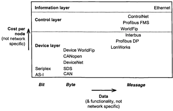
their confusion over the choice of fieldbus for particular applications. This can be illustrated
by the choice shown in Figure 7, of small number of the leading open technologies.
Information layer Ethernet
Data
(& functionality, not network specific)
Figure 7 Network positioning of leading open fieldbus
The major automation manufacturers' promote their now open fieldbus technologies as
universal solutions for most applications, the user merely faces the choice of suitable
network(s) for a particular application from those offered. The choice becomes more complex
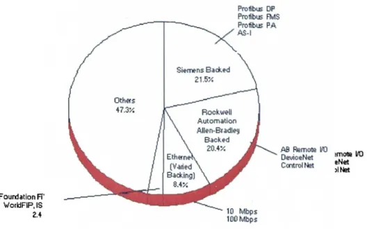
where device suppliers support multiple networks, backed by different major manufacturers,
often offering virtually any fieldbus currently available (Figure 8).
This situation requires the education of potential fieldbus implementers, therefore it was
Founiation P vorkiFipIS
2.4 10 Mbps
100 Mbps
Selection of fieldbus technology & network planning
Frolibtis OP Prolibus F!ulS Prothi PA AS-I
Siemens Backed 21.57
Othecs
Automation AIIen-BradIej tecne Rockwell
Backed
ed
AB Remote LJ
De,AceNet mot 110 Ccntroftt eNet
INet Backing)
8.4
1998 Total: $1.9 Billion (percent of Dollar volumes, products by network interfaces type,
grouped by major backers)
Source: Venture Development Corporation
Figure 8 Worldwide shipment shares of distributed/remote I/O
32
Selection of fieldbus technology
The initial step is to understand the type of application (whether continuous, batch or
discrete) 2° and how the differing requirements will affect the choice of fieldbus and devices.
The company control system strategy could affect the network architecture, either through the
choice of controller (PLC/PC) or a preferred controller vendor. It then follows that a decision
must be made to use open or proprietary networks supported by the controller vendor.
The choice between open or proprietary networks gives the option of the best of breed
products from many suppliers or the security of a single source solution. Open fieldbus
associations must therefore ensure that products from multiple manufacturers operate
correctly by conducting composite testing (physical layer, protocol compliance and device
interoperability). Open fieldbus associations offer a means to check the availability of
equipment and continued development of a technology.
R.S.H.Piggin
Selection of fieldbus technology & network planning
Finally, technical features of the fieldbus should be considered. These are cabling (maximum
length, device power option, connectors, media supported and topology), bridges/gateways,
redundancy (controller and cabling), ability to swap devices under power, transmission of
non-time critical data (e.g. device configuration) and time critical data throughput (to meet
applications requirements).
Many potential users of fieldbus technology stress the real time nature of their applications
and how this can be achieved with different fieldbus, often mistakenly comparing the raw bit
transmission speed across the network. The importance of protocol efficiency, comprising of
the message overhead (any additional information other than the required data) and the
network model, must not be overlooked. The particular network model used will also affect
the ability of the technology to support future technical advances (such as highly distributed
control). Hence the use of the peer to peer network model in newer technologies (including
DeviceNet, ControlNet and Fieldbus Foundation) as opposed to the source-destination model.
The innovative aspect of this work is the development by the author, of a basis for fieldbus
selection by the evaluation of appropriate criteria. The work has been widely disseminated
though the presentation of material at national and international conferences and on the
Automation & Robotics Engineering Business Management MSc module. 21 Selection
advice has also been given to companies visiting the Warwick fieldbus demonstrator, these
have included BMW, Cadbury, Compaq, Ford, GlaxoWellcome, Gillette, Honda, Jacobs
Suchard, Marley Building Materials, Mitsubishi, Nestle, Rover, Seven Trent Water and
Thames Water. This work has been utilised by companies in the choice of appropriate
networking solutions for their applications.
3.3 Network planning & installation cost comparison
Network planning of customer sites has been required where customers were considering the
use of the DeviceNet fieldbus, but are not familiar with the technology. The potential
Selection of fieldbus technology & network planning
The researh engineer performed a spreadsheet analysis in order to estimate incremental
labour and material costs for hardwire, proprietary network and DeviceNet installations. The
installation cost of each architecture is calculated, allowing for the different controller
interfaces, I/O hardware, cabling, trunking and enclosures. This was the first trial of Rockwell
Automation US customer support software in Europe. The figures used in the calculations of
rework, labour and material costs were therefore modified by the author to meet local
expectations. Standard DeviceNet interface costs and hardwire device equivalents have
been identified, incorporated in the spreadsheet and used in calculations. These were
necessary to enable Rockwell Automation sales engineers and customers to apply the
spreadsheet in a consistent and reliable manner.
The installed cost analysis required the network layout to be planned by the customer, often
this had not done. Where the customer did not provide the required information, the
necessary detailed planning of networks was found to be time consuming. A questionnaire
has been developed to give customers an understanding of DeviceNet and the data
requirements for the installation comparison, to encourage suitable data preparation prior to
site visits.
The network data required for the spreadsheet calculation necessitated the estimation of
cable lengths to each network device (from the programmable controller) and a measure of
conventional wiring complexity (device wiring equivalent, necessary for the traditional direct
wiring comparison where each device is directly wired to the controller). Labour, material and
rework costs were agreed with the customer and revised if required. This practice increased
cusLomer confidence, particularly where the conventional direct wiring or legacy network
installation costs were accurate when compared to existing installations. The DeviceNet
network installation cost estimations were then seen as being realistic, even without prior
knowledge of the technology.
Selection of fieldbus technology & network planning
The additional guidance given on device wire equivalence, and spreadsheet data
requirements has assisted sales engineers and customers in the use of the tool. Case study
evidence has shown that the revised labour, materials and rework costs can provide an
accurate estimation for cost comparison between the three different control system
architectures.
Company staff have been given formal training consisting of presentations, sample exercises
and guidance when visiting customers. This has given Rockwell Automation customers the
ability to question the viability, suitability and benefits of various control system architectures
and configurations prior to implementation.
3.4 Configuration tool enhancement
There are different network configuration tools available for DeviceNet, however, the choice is
presently dependent on the chosen controller. Device parameters and configurable options
are described using device specific Electronic Data Sheets (EDS), independent of the
configuration tool used.24 The EDS enables device parameters to be altered (within legal
values) by a user with the aid of help text. However, the EDS does not present the user with
sufficient information to operate a device once it has been configured.
The user must determine the data required to control and monitor a device. The research
engineer proposed the addition of a data and diagnostic sections to the EDS to facilitate
device integration and programming. 25 A method is given to describe and identify the data
mapping format required by a control system integrator and subsequently use this information
in the configuration and programming of a device. Diagnostic text is then associated with the
data mapping to provide predefined diagnostic messages corresponding to data produced by
the device.
The DeviceNet electronic data sheet could be further enhanced to include standard blocks of
Selection of fieldbus technology & network planning
(no faults) prior to operation, then specify the speed and direction of rotation, whilst
monitoring input data for correct operation. The code could be described within the EDS in an
IEC 1131-3 (international standard for programmable logic controllers) language or by neutral
means with Extensible Markup Language (XML), and subsequently imported into a
programming tool or downloaded to a device. Many manufacturers claim compliance to IEC
1131-3 for their PLCs, however this does not indicate PLC programs for one brand of PLC will
operate on another. The use of XML by a number of international standards committees
(including ISO 15745 Open systems application frameworks and IEC 1499 Function blocks
for industrial measurement and control systems) indicates the future direction for textual
specification of engineering and configuration information.
The innovation of this project concerns the addition of EDS user data and user diagnostic
sections to the EDS file structure. These additions will enable a user to identify device data
and utilise or alter predefined diagnostic messaging. The end user or system integrator will
have immediate access to comprehensive diagnostics which, would previously need to be
individually programmed. This work is under review by Rockwell Automation, prior to
submission to the Open DeviceNet Vendor Association (ODVA) System Special Interest
Group (SIG), who manages the development of the DeviceNet EDS.
3.5 Manual design
The networking sections of DeviceNet manuals from different manufacturers are of variable
quality. Experience gained by the author from the integration of devices on the fieldbus
demonstrator and from observations made by end users has led to the development of best
practice guidelines. 26 In the manufacturing industry, the use of networking technology in
place of traditional methods has been likened to the replacement of relay logic with
programmable logic controllers (PLCs). 27 Since many users are likely to be unfamiliar with
the technology, it is necessary to provide suitable supporting documentation. 28 The
DeviceNet manual design paper outlines, with examples, the information required by end
users or system integrators.
Selection of fleldbus technology & network planning
The following information is recommend for inclusion in DeviceNet manuals:
DeviceNet overview (key characteristics e.g. Device level network, CAN based, IPR
owned by ODVA & ODVA contact details for further information).
• Example schematic network layout.
• DeviceNet network topology/cabling options (thick, thin & flat cable & current limits).
• Distance/baud rate options (trunk & drop cable lengths vary with baud rate & media type).
• Device configuration (Dip switch/settings software settings).
• Device/network diagnostics (DeviceNet module & network status LED5).
• Device I/O data format/mapping (include diagnostics & alternative configuration options).
• ODVA device profile fault codes (DeviceNet Specifications Volume II).
• Manufacturer specific fault codes.
• DeviceNet communication supported message types, class services & objects
(appendix).
• Printed version of EDS /electronic version of EDS on floppy disk (an EDS is required for
device configuration, a printed copy of the EDS contents is only suitable for simple
devices).
Where other documentation on network configuration is supplied or the simplicity of the
device does not warrant more than a small leaflet, then the minimum information to be
included in a device manual is recommended.
This provides a guide to the provision of high quality, consistent, DeviceNet documentation
that can be easily understood by the end user/system integrator. Thus ensuring information
that is required by DeviceNet implementers is not inadvertently omitted. It is under review by
Fieldbus application case studies & benefits
4 Fieldbus application case studies & benefits
4.1 Background
The initial slow market implementation of fieldbus indicated that many potential users were
not aware of the advantages the technology offers. Fieldbus organisations have claimed a
number of benefits that may be obtained through fieldbus, however these were anticipated
benefits based on information relating to the process industry, not manufacturing.
Application case studies, representative of various industrial sectors were performed to
ascertain the actual benefits realised by DeviceNet users. 3° The case studies are based on
interviews with control system engineers who discussed their experiences with fieldbus.
Eight companies were investigated, seven had installed multiple networks. One was in the
process of examining the use of open networking technology, and was able to comment on
perceived benefits based on proprietary networking knowledge.31
The companies involved were from the automotive, building materials, computer manufacture,
packaging, paper production and water treatment industries. These were among the earliest
implementations of DeviceNet in Europe.
4.2 Automotive
According to Josphine Robinson, DeviceNet is used by Ford for PC control of automotive
transmission assembly lines. 32 Seventy industrial PCs are linked by Ethernet, each
controlling a single DeviceNet network. The DeviceNet networks comprise 3-5 I/O blocks, 3-5
pneumatic valve manifolds and 2 AC motor drives.
1.1.1 Benefits
• Standardisation - modular design of lines, control program and DeviceNet device
configurations.
• Decreased downtime due to the provision of diagnostics and modularity.
• "Data collection faster, easier and cheaper."
R.S.H.Piggin
Fieldbus application case studies & benefits
. Ease of configuration.
The enhanced data collection ability of DeviceNet, modularity of components and lower
system costs were acknowledged as the principal benefits.
4.3
Building materials
Compton John, thecontrol systems manager at Marley Building Materials stated that
DeviceNet has been selected as a standard fieldbus network for all manufacturing sites.M
Two separate site installations are examined. DeviceNet has been utilised to control the
transfer of sand by conveyors to one of four silos after initial delivery from lorries at one
location. The DeviceNet system comprises three networks using 2 PLC DeviceNet interfaces.
One network comprises 4 weigh scales and 3 I/O blocks (Digital Inputs, Outputs and
Analogue). The second network has a weigh scale, an ASI Gateway and an I/O block. The
third has a single I/O block.
1.1.2
Benefits
• Standardisation of systems.
• Lower installation and commissioning costs (subcontracted).
• Space saving in panels.
• Commissioning reduced from 6 man days to 3 man days.
The ridge tile application comprises 3 networks with 60 drives (paint stirrers, conveyor drives),
a weighing amplifier, proportional valves, proximity sensors, solenoids and an operator
interface. The master PLC has 3 DeviceNet interfaces, one with 3 PLCs acting as slaves, 2
ASI gateways & I/O blocks, the remaining network has a further 3 I/O blocks and 2 AC drives.
1.1.3
Benefits
• Reliable real time communication between PLCs.
Fieldbus application case studies & benefits
• Testing in situ (not possible previously).
• Reduction in panel size and number.
• Panel design effort minimised through standardisation.
• Commissioning reduced from one week to 2 days.
There are a number of significant benefits apparent from the use of DeviceNet in both
projects. The use of DeviceNet for real-time communication was chosen as an alternative to
interlocking PLCs together (using interposing relays), the control systems manager stated no
other network was suitable. 35 This was due in part to the real time performance requirements
and the lack of a control level network interface (ControlNet) for that particular PLC. The
installation of hardwire interlocks was estimated to take 3 weeks, by using DeviceNet this was
reduced to two days. The panel installations are decentralised to allow zoning of equipment
for safety and operational reasons, enabling panel designs to be standardised. DeviceNet
weigh amplifiers allows the measurement of negative tare weights (i.e. when a hopper is
empty), which was not previously possible (using 0 - lOmv). With a calculated error of 3
kilograms on each mix, one hopper would waste £97 of material per day, £35,500 per year.
The study was conducted shortly after the initial installations, the senior installation engineer
later stated that ease of maintenance was also a benefit and the fieldbus technology was
simple to use.
4.4
Computer assembly
DeviceNet is utilised to control operator stations on a conveyor, all the networks are similar,
approximately 15m long. A typical network has 26 photoelectric sensors and 3 I/O blocks
(input & output). The I/O blocks integrate proximity sensors and pneumatic solenoid valves.
Brian Loy of Compaq described the main benefits listed below.
1.1.4
Benefits
• Installation reduced from 2 weeks to 5 days.
• System construction and testing off site.
• Ease of Configuration and Maintenance.
R.S.H.Piggin
Fieldbus application case studies & benefits
• Reduction in cabling.
• Increased flexibility (through easier system reconfiguration).
The main benefits realised were the speed of installation and ease of maintenance. The
diagnostic capability of the network was a prime factor in the decision to use this particular
fieldbus.
4.5
Packaging
Bill Wyville of Tambrands indicated that DeviceNet is utilised to control the delivery and
packaging of hygiene products, interfacing 60 small variable speed drives, 6 larger AC drives
and 20 I/O blocks. Twenty-five production machines discharge to a nine lane mass conveyor,
which then discharges to three lanes and subsequently to a dedicated bundling and carton
line.
1.1.5
Benefits
• Control system saving - 46% (traditional compared with DeviceNet).
• Installation without production disruption.
• Flexibility.
• Standardisation - modular design enabling reuse of control program and DeviceNet device
configurations.
Use of DeviceNet in this application gave significant cost and commissioning savings.
Undisrupted production during installation was believed to be an important benefit. The
flexibility of the network was crucial to installing additional lines without major control system
changes. Incorporation of the extra lines using traditional methods would have been
impossible to design and implement due to time pressures.
4.6
Paper production
Fieldbus application case studies & benefits
prepare new tubes to accept paper. 37 One network is used to control each machine,
comprising a small PLC with two AC drives, 7 photoelectric sensors and 16 proximity sensors
connected individually with a DeviceNet interlace for standard (not networked) sensors.
1.1.6
Benefits
• Reduced wiring.
• Faster and easier commissioning - reduced by 50%.
• "Plug and play" diagnostics.
• Standardisation of design, configuration and system programming.
DeviceNet was specified mostly for diagnostic and commissioning reasons. Significant time
savings were made during system design and configuration.
4.7
Water treatment
DeviceNet was being evaluated by Dewplan for the control systems of treatment plants, for
potential use in power stations, refineries, chemical plants, silicon manufacture and other high
technology industries. DeviceNet was considered for process monitoring and the internal
cabling of Motor Control Cubicles (MCCs). Following a detailed discussion with the Controls
and Instrumentation manager, Mr Andrews, the main benefits anticipated from DeviceNet
implementation are given.38
1.1.7
Benefits
• Commissioning: Hardwired 7-10 weeks reduced to 7- 10 days.
• Design effort reduced by almost 50% (man weeks).
• Ability to connect a laptop computer to configure and check system.
• Flexibility in design (in comparison with a proprietary network).
• Standardisation (reducing design and commissioning further) - changes easier to
incorporate.
• Reduction of inter-panel wiring (reduction in panel complexity and design effort)
• Panel space saving or do without panels entirely.
Fieldbus application case studies & benefits
• Cabling off site possible.
The preciseness of the expected benefits is due to the experience gained in the
implementation of proprietary networks, network planning (including installed cost analysis)
and discussion.
4.8 Application
A comprehensive insight into the impact of fieldbus technology was achieved during the
preparation of these case studies. Discussions involving project engineers presented
information that was previously intangible and not available from companies or fieldbus
organisations. Evidence of actual benefits in different industrial sectors has been obtained.
The knowledge acquired during the case studies has been disseminated to system
integrators and end users through discussions in companies, visits to the University, trade
shows, conferences, presentations and Rockwell Automation marketing material. Examples
of the savings achieved are included in the draft fieldbus guide soon to be published by the
British Standards Institution. The use of real application benefits in place of anticipated gains
Fieldbus demonstrator
5 Fieldbus demonstrator case study
5.1 Overview
The adoption of the open fieldbus systems relies on the fieldbus technology operating reliably
when composed of multi-vendor equipment. If devices fail to communicate the user will have
difficulties determining the cause and the offending equipment. Therefore the interoperability
of equipment from multiple suppliers needs to be shown. In order to illustrate interoperability
and the benefits of fieldbus technology, a fieldbus demonstrator has been developed.
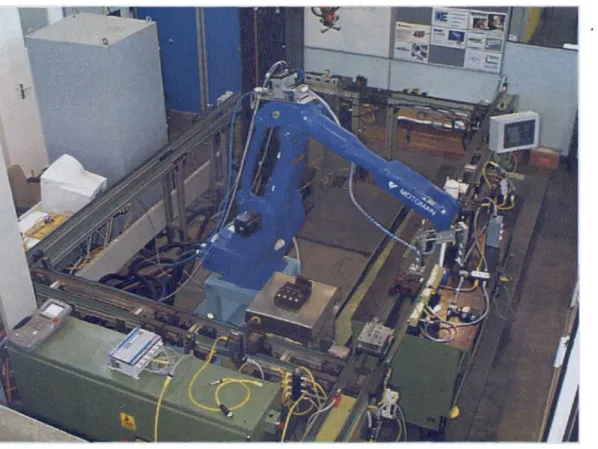
Hardwired I/O has been completely replaced by a DeviceNet network and devices, exceeding
50 nodes, with equipment from over 30 different manufacturers (Figure 9).
1 ___
• .i, --- .
-t,I% :-.
J
£' ______
.
w
4
Figure 9 Fieldbus demonstrator
The demonstrator is a fixed display located in the engineering hall of the International
Manufacturing Centre, Warwick Manufacturing Group at the University of Warwick. The
flexible assembly cell consists of a rectangle of conveyor (2.5m x 4.5m) for moving pallets,
with two robots performing assembly and weighing operations. DeviceNet provides
Fieldbus demonstrator
diagnostic information that would not be available using the old traditional parallel wiring
method or legacy networks. To demonstrate this facility a large LED (light emitting diode)
message screen and a Supervisory Control And Data Acquisition (SCADA) software package
have been installed. Both are interfaced to the PLC controlling the cell. DeviceNet
equipment is installed to show variety and particular network features.
5.2 System architecture
The principal demonstrator networked components are shown in Figure 10.
The PC has four functions:
1. Online and offline programming of the PLC.
2. DeviceNet scanner and device configuration (device configuration is also performed with a
hand held configuration tool or a laptop PC with PCMCIA DeviceNet interface).
3. SCADA configuration and display.
(0
L 0)
Co 5
(00 a)o 0 o
'U)
ui
U,
. a)
> E E
o
E
a)
• <)
o
-
oo
0
-J 0 0 I-C) G) 4-. U I-(0 1 0 4S (5 4-In C 0 E C, a C, a- I-a) U--o — a) _iZQ_ . oö . — ) 2 E
) . 2
0 Q -(/Da)0 c) C.'J U) >' Co 0 (I, a +
EIJ
•j"
I ct a) -< . ra) a) C >-I oCo '-C/) a-a U-0(0-at
oCo
0C '•- — 0 a) L) Co='-2I
C)0
0
Co
0(/) _Jt
Fieldbus demonstrator
The Industrial Personal Computer (IPC) is used for real time control, demonstrating an
alternative control strategy to the more traditional use of a PLC.41
The IPC has the following functionality:
1. Online and offline programming.
2. DeviceNet interface and device configuration.
3. SCADA configuration and display.
4. Internet web server.
5. HMI configuration.
Many functions of the PC and PLC can be combined on one platform on an IPC, in some
circumstances, providing a cost-effective alternative.42
5.3 System Integration
The PLC controls the conveyor devices via the DeviceNet scanner module, transferring
device input/output and scanner/network status information. The PLC program incorporates a
routine developed to display device and network errors. When errors are induced, for
demonstration purposes by removing multiple devices, network communication errors are
indicated with device specific fault and location information. The messaging display is driven
by the PLC via RS -232 communication (installed prior to the availability of suitable DeviceNet
displays). SCADA and the PLC programming software utilise Data Highway +, an
Allen-Bradley (a Rockwell Automation brand name) proprietary network interface available on the
PLC processor. This avoided the addition of further network interfaces in the PLC rack. It is
regarded as important to show one network interface can replace all the original PLC I/O
cards.
An embedded PLC has been incorporated into the system to show the potential to remove the
control cabinet required by a PLC, by placing the embedded device directly on the machinery.
Fieldbus demonstrator
control cabinets can cause in a DeviceNet installation, as part of their visual factory
principle. The addition of another PLC proves the multi-master capability of the network
(some networks only allow one controller). The embedded PLC is mounted on the Motoman
robot, operating the robot gripper and providing feedback.
The ASEA robot has been interfaced via a micro PLC by an MSc student. 45 Hardwiring of the
I/O between the robot and the PLC has been kept to a minimum by placing the micro PLC
adjacent to the robot controller. The micro PLC program has also enabled the number of
wires to be minimised and reduced the data transmission to the PLC. This is achieved by
providing local control and status feedback, rather than simply I/O messaging. The ability of
the network to support decentralised control is therefore demonstrated.
The radio frequency identification system (RFID) has been replaced as part of the same
student project, to indicate the broad spectrum of equipment that can be used on DeviceNet.
The RFID system enables the identification of pallet type and current status (full or empty)
with data being read and written by the PLC according to robot operation (controlled by the
PLC).
DeviceNet integration of the Motoman robot was less complex, being a network interface card
directly mounted in the robot controller. Messaging between the PLC and robot appear as
local I/O to both, removing the need for the time consuming wiring required to interface the
ASEA. The difference was considerable, to interface the ASEA required the author and
student to study wiring diagrams of the robot I/O, which was found to have few I/O points left.
A scheme was then developed for the communication, programmed in the micro PLC, to
maximise the remaining available I/O. Whereas the Motoman installation took minutes, only
requiring network settings and I/O sizes to be specified. The I/O available on the interface
allowed for further expansion and did not limit existing robot I/O.
Human Machine Interface (HMI) enables comprehensive operator monitoring and control of
the system. Monitoring of system status, drive speed & current, motor temperature, linear &
Fieldbus demonstrator
shaft position, pallet status and device diagnostics is possible. The producer/consumer
based communication of the network is fully implemented in this device and allows integration
of HMI of this sophistication on to a device level network. Even though all other devices are
configured to respond as slaves to the PLC master when communicating, the HMI is set to
produce data at the request of the master (PLC) and consume responses (to master
requests) from selected slaves. This avoids duplicate messaging to PLC and HMI from
slaves, significantly reducing network bandwidth utilisation. If the same functionality were to
be implemented using a source destination network, each slave device would need to
respond to communication requests from both the master PLC and HMI. This is would cause
a substantial increase in network traffic, likely to impact the real time quality of the network,
becoming unsuitable for device control.
The SCADA and Internet server were implemented as student projects. 46 The SCADA was
originally configured to show status and limited trending and diagnostic information. 47 The
SCADA functionality has been enhanced to demonstrate the diagnostic capability of the
network, by incorporating graphical and textual indication of device status and fault
conditions. Development of the Internet server has been completed to prove the concept of
remote monitoring using 'live' data. 48 While data cannot be provided in real time due to
Internet access, system information has been shown to be accurate to within seconds.
5.4
Research engineer contribution
Dr. Ken Young initially implemented DeviceNet on the demonstrator, to a point where the
control system was a mix of hardwired and fieldbus devices from a limited number of
manufacturers. The research engineer obtained and integrated a wide range of fieldbus
devices to show true multi-vendor interoperability and the benefits of fieldbus. The ASEA
robot, two Personal Computer controllers, Internet monitoring, Promise (DeviceNet network
design software update of the original work completed by the research engineer) and partial
Supervisory Control and Data Acquisition (SCADA) package integration were student projects
Fieldbus demonstrator
5.5 Further work
New features of DeviceNet incorporated into new products will be integrated. This will include
a facility to automatically reconfigure a device should a replacement be connected to the
network with the identical characteristics. A paper based on a portfolio submission is
planned to highlight the advantages of peer to peer communication, and how it has been
applied on the demonstrator.49
The combined use of Unified Markup Language (UML) and Extensible Markup Language
(XML) will be investigated. On going work is already utilising UML in the SALVO control
system for object orientated programming. XML offers a neutral language for UML data
transfer, device profile definition and possibly function blocks.
5.6 Innovation
&
application
The fieldbus demonstrator at Warwick is a unique facility showing a range of working,
interoperable equipment from a large number of different manufacturers. The interoperability
of devices is crucial to the success of open fieldbus technology, this facility clearly
demonstrates equipment interoperability.
The integration of prototype devices has given companies the opportunity to test devices in
an interoperable environment not normally available to them. Where devices have not
functioned properly, or have not been implemented correctly according to the DeviceNet
Specifications, the circumstances have been reported to the companies concerned. This has
assisted companies in the development of product and afforded significant cost savings.
Fieldbus users have also been spared the inconvenience of system failures, avoiding
performance and suitability fears of the new technology.
The fieldbus demonstrator has been used to illustrate the advantages of fieldbus technology
to potential users. The facility shows how system complexity can be reduced with less
cabling, while system functionality is enhanced. The capability of fieldbus to improve
diagnostics and to support alternative control methodologies (utilising HMI, multi-master &
R.S.H.Piggin
Fieldbus demonstrator
highly distributed control) is shown. The flexibility and ability to rapidly reconfigure the
network and devices is also demonstrated. The demonstrator displays the key benefits that
manufacturers can achieve to meet business demands. For example, the Ford plant
manager, Miro Suga indicated that the long-term objectives of having a re-usable and
convertible plant have been achieved at Halewood. Fieldbus technology has enabled the fast
installation and launch of new assembly lines, increasing reliability, maintainability and
flexibility.50
These benefits have been disseminated to a wide audience. Most companies (OEMs, system
integrators and end users) that have implemented or are evaluating DeviceNet have visited
the demonstrator, including AWRE, BMW, BNFL, Cadbury, Compaq, Ford, GlaxoWeilcome,
Gillette, Honda, Jacobs Suchard, Marley Building Materials, Nestle, Rover, Seven Trent
Water and Thames Water. 51 The demonstrator has been featured in a number of national
Transitoiy connections utiising fieldbus
6 Transitory connections utilising fieldbus
6.1 Fieldbus benefits
The benefits most frequently cited by users of fieldbus technology have been flexibility,
design, speed of commissioning, diagnostics and maintenance. The exchange of digital
information is also considered important, providing more accurate data capture than analogue
systems and allowing the use of data that was previously unavailable. These benefits can
be utilised in new areas with the novel application of fieldbus technology.
Work done at the University of Warwick by the author has shown fieldbus can be used over
transitory connections for robotic tool changers and laser scanners used for machine safety.
Transitory connections in this instance are those network connections that are designed to be
disconnected and reconnected whilst the network is under power.
Dr. Young had demonstrated the use of fieldbus with transitory connections to pallet tooling
on the SALVO project. Further development by the author in collaboration with Sick & Pilz
has incorporated connectivity for a machine safety network on the same tool pallet. The
research engineer has achieved similar benefits with fieldbus transitory connections
implemented on a robotic tool changer.
Use of a safety-related fieldbus has enabled the provision of safety measures in an
application, which would not otherwise be feasible using traditional hardwiring, due to the
complexity and large amount of wiring required.
The reduction in the number of cores has been achieved by the use of fieldbus in new
applications, such as over slip rings, flexible and transitory connections, where the large
number of conductors/connectors required would previously have been prohibitive.
R.S.H.Piggin
Transitory connections utiising fieldbus
6.2 Controller Area Network over slip rings
The Controller Area Network (CAN) technology has been used successfully in proprietary and
open protocol formats over slip rings to simplify systems engineering. A proprietary CAN
application example involves the indexing of a registered embossing machine for beer can
manufacture. CAN data, regulated and unregulated 24v and 3-phase power are all passed
over slip rings to 24 servo drives. The application design was based on CAN from the outset
by the system integrator, simplifying complicated system integration. 57 DeviceNet has also
been utilised over slip rings to control the manufacture of car seat foam for similar reasons. A
networked programmable logic controller (PLC) controls the moulding process on a
continuous track with drives and via slip rings, pneumatics and thermocouples. Both
applications have proved very reliable according to the system integrators, with no faults
experienced due to the transmission of data in this manner.
6.3 Robot flexible couplings and links
Development of a prototype smart petrol pump, capable of opening a filler cap, inserting a
hose and filling a fuel tank, suffered significant electrical noise problems, mainly due to the
large volume of hardwiring. DeviceNet is used to replace the hardwiring (with I/O points along
the length of the robot arm), reducing sensor wiring, enabling fuel, hoses, motor wiring, and
pneumatics to be routed through three gantry racks and two rotational links. The system
integrator said the use of fieldbus in this application was essential in the development of the
final prototype, enabling the sensor wiring to be kept to a minimum.59
6.4 Transitory connections using CAN
Three applications have utilised the need for fewer wires, and the ability to add and remove
devices from a fieldbus under power. All the applications are in the SALVO (Structurally
Advanced Light Weight Vehicle Objective) cell, two DeviceNet transitory connections are
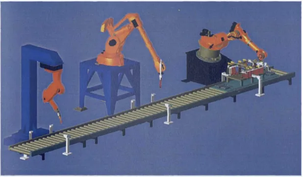
used on separate networks, one on a conveyor, the other on a robot (Figure 11). The third
network is Safetybus p, (another CAN based fieldbus) used purely for connection of safety
Transitory connections utiising fieldbus
p) as it travels along the conveyor and is reconnected at each robot station. The robot
transitory connection is for a tool changer.
6.5 Tool pallet quick connect
A complex body in white assembly tool moves between three cells (Figure 11). The tool
pallet has twelve automatically controlled clamps each driven by a locking cylinder, with a
minimum of two sensors per cylinder to hold the work piece and two laser scanners provide
safety guarding. The tool is located on a pallet that runs along a roller conveyer 18m long.
When the tooling enters a cell it is first located on the conveyor by a shot bolt and then a
quick connect device with DeviceNet, Safetybus p, 24v power and a pneumatic supply hose is
fired into a docking plate on the tool. Once connected the four nodes that control the tooling
(three solenoid banks and an I/O block) and the laser scanners secure communication with
the PLC and safety controller respectively, then the tooling actions commence.
,
'' a
-
'
.1
iI
LL
ii- "-..-.
-..---,--- - -'--'.Figure 11 SALVO cell showing the tooling, conveyor and robots
Had traditional wiring been used, the number of individual connections would be far greater,
complicating fault finding and repair. With just five connections the size of the pins can be
larger, increasing robustness and duplicated to give redundancy if required. This has not
Transitory connections utiising fie!dbus
been done on this occasion. No failures due to the quick connectors have been logged by the
SCADA package in over 20 months of operation.
6.6 Robot tool changer
The tool changer is mounted on the central robot of the SALVO cell (Figure 11), on the wrist
of an ABB robot. The DeviceNet network runs from a PLC, into the base of the robot, exits
half way down the arm and is connected to the fixed half of the tool changer (Figure 12). The
trunk (thick) cable is terminated in the connector of the tool changer, with the drop (thin)
cable passing through the tool changer contacts via a termination block and to a DeviceNet
I/O block.
A
Figure 12 Tool changer showing DeviceNet trunk and drop cabling
The network utilises the standard connections provided at the robot base and on the arm.
Transitory connections utilising fieldbus
errors were discovered, believed to be due to the size of pins. By using the network the PLC
is able to detect tool connection and identify tool type. This is achieved by assigning a unique
(network) identity to each I/O block mounted on a tool.
The tool changer provides transitory connections for the network and pneumatics to control a
self-drill drive screw. The single I/O block is sufficient to provide all the required inputs and
outputs.
Similar benefits have been achieved with the tool changer as with the conveyor quick
connect. The reduction in wiring complexity would facilitate rapid fault diagnosis and repair,
had there been any problems. The reduction in cabling down the arm has made cable
dressing easier and more robust. Tool identification is set via software (over the network) by
changing the network address of the I/O device, providing a more secure and less error prone
method than manual coding.
6.7
Innovation & application
The novel use of fieldbus for transitory connections is a new application of the technology.
Transitory connections are not possible for all fieldbus technology, for example a ring
topology network that reconfigures node addressing on device disconnection. The use of
transitory connections with CAN based networks has proved the viability of the concept,
affording greater flexibility and functionality. The utilisation of a safety network (in place of
hardwiring) is not yet accepted practice by the Health and Safety Executive (HSE). 6° The use
of transitory connections for safety inputs is a demanding test of the technology, and is not
possible with traditional methods.
Fieldbus work performed (tool changer & Safetybus p) in the SALVO project has been
disseminated to participating companies through presentations, visits and journal papers.6162
The safety fieldbus component has been used to demonstrate the technology to HM Factory
Inspectors (HSE) in order to promote its acceptance. The safety-related technology was also
displayed at the UK launch, held at the University.