University of Warwick institutional repository: http://go.warwick.ac.uk/wrap
This paper is made available online in accordance with publisher policies. Please scroll down to view the document itself. Please refer to the repository record for this item and our policy information available from the repository home page for further information.
To see the final version of this paper please visit the publisher’s website. Access to the published version may require a subscription.
Author(s): Robert E. Critoph, Steven J. Metcalf and Zacharie Tamainot-Telto
Article Title: Proof of Concept Car Adsorption Air Conditioning System Using a Compact Sorption Reactor
Year of publication: 2010 Link to published article:
http://dx.doi.org/10.1080/01457631003604459
Publisher statement: ‘This is an electronic version of an article published in Critoph, R. E. (2010). Proof of Concept Car Adsorption Air Conditioning System Using a Compact Sorption Reactor. Heat Transfer Engineering, Vol. 31(11), pp. 950 – 956. Heat Transfer Engineering is available online at:
Proof of Concept Car Adsorption Air Conditioning System Using a Compact Sorption
Reactor
Robert E. Critoph, Steven J. Metcalf, Zacharie Tamainot-Telto
School of Engineering, University of Warwick, UK.
Address correspondence to: R.E Critoph, School of Engineering, University of Warwick, CV4 7AL, UK. Tel. +44 2476 523137, Fax +44 2476 418922, e-mail
ABSTRACT
A prototype compact sorption generator using an activated-carbon ammonia pair
based on a plate heat exchanger concept has been designed and built at Warwick University.
The novel generator has low thermal mass and good heat transfer. The heat exchanger uses
Nickel brazed shims and spacers to create adsorbent layers only 4 mm thick between pairs of
liquid flow channels of very low thermal mass. The prototype sorption generator
manufactured has been evaluated under the EU car air conditioning testing conditions.
While driven with waste heat from the engine coolant water (at 90oC), a pair of the
current prototype generators (loaded with about 1 kg of a carbon in each of two beds) has
produced an average cooling power of 1.6 kW with 2 kW peaks.
INTRODUCTION
Adsorption refrigeration and heat pumping devices have the potential to reduce harmful and greenhouse gas emissions (CO, CO2, NOx, SOx …) and to produce substantial fuel savings. The primary energy source for state of the art Mobile Air Conditioning (MAC) systems in cars is mechanical power produced by the engine, to drive the compressor, and electric power to run the fans, which in turn is again derived from the mechanical power from the engine itself. The air conditioning system has a considerable impact on fuel consumption. For a B class car on an urban cycle under severe ambient conditions (35°C and 60% RH) it can increase car fuel consumption by up to 70% [1]. The CO2 emissions due to the use of MAC ranges from 4 to 8% on a yearly basis. This is equivalent to CO2 emissions from 5 to 10 Million tons of CO2 per year in Europe and correspondingly more globally [1].
The major technical challenges to developing a sorption system to use the waste heat of a car engine are:
2. To obtain a sufficient Coefficient of Performance (COP) to deliver adequate cooling to the vehicle under all driving conditions.
The intensification of heat transfer within sorption generators has been the focal point of adsorption refrigeration R&D at Warwick University, aimed at high power density and COP for both cooling and heating systems. The concept of a plate heat exchanger (PLATEX) applied to sorption generators (adsorber/desorbers) for cooling and heat pump applications has been investigated and has proven to be interesting. Initial computational modelling of a compact generator using the carbon-ammonia pair reveals an attractive performance: specific cooling power (SCP, the cooling power per unit mass of adsorbent) from 1 kW kg-1 carbon up to 6.5 kW kg-1 carbon; specific heating power 0.250 kW kg-1 carbon up to 2.5 kW kg-1 carbon with cooling COP varying between 0.5 and 1.2 [2,3].
In ‘Extreme’ conditions (motorway driving at an ambient temperature of 38°C) heat is available at 90°C and a COP of 0.24 is required. This is easily achievable with the system
described below and we will concentrate on performance under the more onerous ‘Normal’ conditions.
There is also a ‘cooldown’ test condition: water inlet to condenser and adsorber 48°C, evaporating temperature 20°C, cooling power 4kW. This corresponds to starting the system
after the car has been left for a long time in a hot environment.
A further requirement is that the total system volume should be less than 16 litres and mass less than 35 kg.
SYSTEM DESIGN
It is well known that for all sorption systems there is a trade-off between the internal thermal regeneration employed (and hence efficiency) and the power density that can be obtained (and hence physical size for a required cooling capacity). In the case of car air conditioning with a driving temperature of no more than 95°C and ambient temperature that could have a typical value of 30°C there is very little gain to be had from complex many-bed
configurations, and a simple two-bed system with mass recovery was selected. Figure 1 is a system schematic. Valves V1-V4 may be set so that hot water from the engine cooling jacket passes through Generator (adsorber/desorber) G1 whilst water from a fan coil cools Generator (adsorber/desorber) G2 towards ambient, or vice versa. Operation is straightforward:
valve V8 to G2 where it is adsorbed. The heat of adsorption is removed by pumped water that is circulated through an air cooled heat exchanger via pump P2 and valves V3,V4.
2. External heating and cooling of the beds stops whilst valve V10 is briefly opened for mass recovery. This allows a rapid transfer of ammonia from G2 to G1 as the pressures equalise. The effectively adiabatic desorption from the hot, previously high pressure bed results in a further reduction in concentration and a corresponding increase of the concentration of the cold previously low pressure bed. The increased concentration swing over the whole cycle results in both higher cooling power and COP.
3. Now G2 is heated to desorb ammonia and G1 cooled to adsorb ammonia as in phase 1 but with G1 and G2 interchanged. Ammonia flows from G2 through V9, condenser, expansion valve V5, evaporator, check valve V7 to G1.
4. Mass recovery as ‘2’.
The whole process then repeats as above.
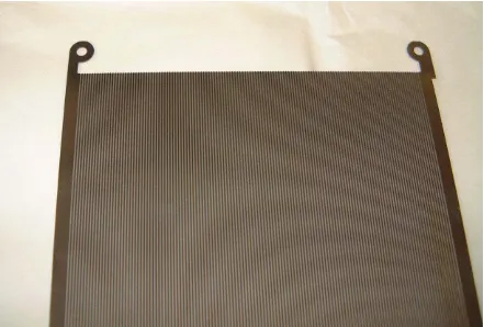
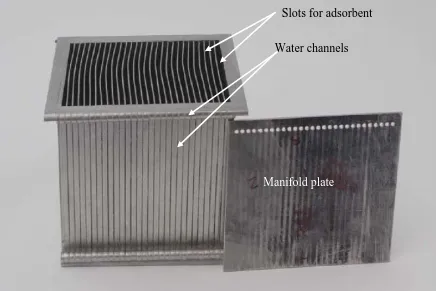
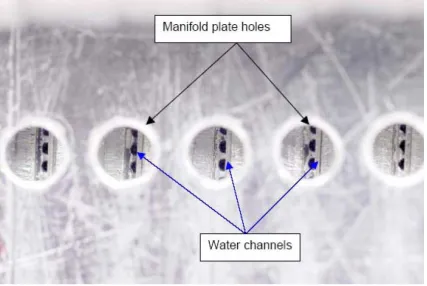
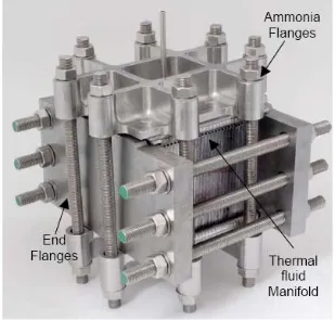
particular flow cross section, uniform heat flux both in flow direction and around periphery, and uniform wall temperature, from Holman [4]) the water side heat transfer coefficient based on the projected area of the plate is approximately 3800 W m-2 K-1. The heat flux per unit temperature difference (UA in W K-1) value for fluid heat transfer has been calculated at 4200 W K-1. The plates with their water channels were fabricated from pairs of stainless steel shims. 0.65 mm thick shims, approximately 150 mm x 150 mm were chemically etched to create ‘D’ shaped channels (Figure 2) which approximated to 0.5 mm square cross section. When brazed to 0.25 mm thick plain shims the pairs form the required water flow channels. Between each of the shim pairs a 4 mm thick U-shaped spacer contains the carbon adsorbent. A total of 28 shim pairs, 29 spacers and 2 end plates are nickel brazed in one operation to form the core of the adsorption reactor (Figure 3). The water manifold is also shown and a close view of the channels through part of the manifold in Figure 4. The whole assembly, in Figure 5, shows the flanges needed to retain the walls against internal ammonia pressures of up to 30 bar. The ammonia inlet/outlet connection is in the centre of the upper face. The threaded tie rods enable the reactor to be dissembled but a production version would be welded and hermetically sealed.
The carbon used (Chemviron SRD1352/3) is compacted into the 4 mm slots and initial estimates were that its effective conductivity would be 0.4 W m-1 K-1. The ammonia mass concentration (x) as a function of temperature (T) and saturation temperature (Tsat) is given by
the Dubinin equation [5] as modified by Critoph [7]:
− − = n
s a t
T T k x
x 0e x p 1 (1)
Where:
k = 12.5626 and n = 1.7366 are constants found by experimental curve fitting to porosity data measured using a Rubotherm magnetic suspension balance.
T is the temperature (K)
Tsat is the saturation temperature corresponding to the adsorbate pressure (K)
For testing in the laboratory, two sorption generators were constructed in a test rig as shown in Figure 6. Hot and cold water tanks of 120 litres capacity were used to provide water for heating or cooling the generators in a controlled fashion and solenoid valves enabled rapid switching of the hot and cold flows to each generator.
The ammonia leaving either generator was directed via a check valve to a water cooled plate condenser, rather than an air cooled condenser as in the vehicle application. This was more convenient in the laboratory when trying to maintain steady condensing conditions. The liquid ammonia was metered via two solenoid valves into a large flooded evaporator; again this was convenient for maintaining steady conditions in laboratory tests. The evaporator was used to chill a steady controlled water flow and the temperature drop monitored by K-type thermocouples.
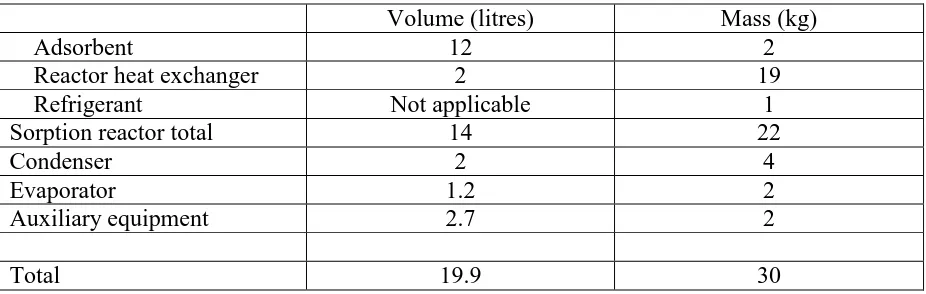
As stated above, the total system volume should be less than 16 litres and mass less than 35 kg. Table 3 gives the mass and volumes of the whole system and components. The total volume is slightly over target, but achievable in a future version.
EXPERIMENTAL RESULTS
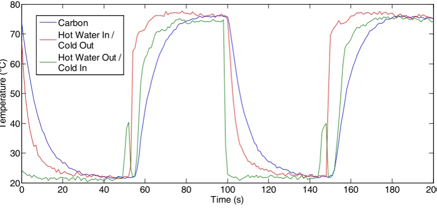
The sorption generator was initially evacuated and then filled with enough ammonia in order to raise the pressure to just above atmospheric, with the condenser and receiver disconnected. The generator was then put through several heating and cooling cycles corresponding to pressurization and depressurization of the generator with very little adsorption and desorption. The test conditions are:
- Heating water flow rate: 12 litre min-1 - Cooling water inlet temperature: 21°C - Cooling water flow rate: 12 litre min-1
The experimental results of the temperature profiles are presented in Figure 7. Water temperatures were measured by K-type sheathed thermocouples in the water flow at the inlet and outlet of the generator and the carbon temperature was measured by a 1 mm diameter sheathed K-type thermocouple inserted centrally in the central layer of carbon. Two complete cycles of heating and cooling are shown. Because the temperatures are measured in the inlet and outlet of the water flow and the flow direction reverses in heating and cooling, at each half cycle the hot inlet temperature becomes the cold outlet temperature and the cold inlet temperature becomes the hot outlet temperature. The heating and cooling is extremely rapid: cooling of the adsorbent from 75°C to 30°C with 21°C cooling water takes just 17 seconds.
During the first 5 second period, the heat exchanger shims are heating rapidly which distorts the overall UA value of the unit and creates the apparent high adsorbent thermal conductivity. When a more stable state is reached and the majority of the heat transfer is to the carbon, a true value for the adsorbent conductivity can be obtained. The average value of 0.42 W m-1K -1
was calculated over a ten seconds measurement period. After this period, the fluid inlet and outlet temperatures become too close to determine an accurate value for the heat output due to measurement noise. The experimental value is extremely close to the 0.4 W m-1K-1 which has been assumed in previous computational modelling and was based on experimental measurements.
The prototype was subsequently tested for its cooling production while mounted on the full laboratory air conditioning system test rig driven by heat from water at up to 90ºC. At the modest driving temperature of 90°C the benefit of thermal regeneration between the two
generators is minimal and only mass recovery was used. One generator temperature and pressure cycle with 90ºC driving temperature is shown in Figure 9. The bed is initially at its maximum temperature of 88°C. The combination of mass recovery (briefly opening a valve
to the low pressure bed) and the sudden influx of cooling water results in a rapid drop in both temperature and pressure to about 55°C and 7 bar within about 5 seconds. The lower pressure
bed and heating water decreases; the rate of desorption and hence condenser heat rejected falls, corresponding to the slight drop in the condensing pressure. The cooling power (Figure 10) from 75 to 150 seconds corresponds to the vapour from the evaporator going to the other bed. The cooling power in both half cycles is not completely identical, but this is due to minor and unintentional differences in the generators, occurring during the manufacturing process. The test conditions and results are presented in Table 4 both for nominal driving temperatures of 80 and 90°C. The average cooling production of 1.6 kW with mass recovery
corresponds to an SCP of 114 W per litre of generator volume or 800 W kg-1 carbonand a COP of 0.22 which is close to the target value of 0.24. The COP was calculated as the total cooling power integrated over a complete cycle divided by the high temperature input power to the generator integrated over the cycle. It should be remembered that the selection of the adsorbent (Chemviron carbon SRD1352/3) and the design of the generator was based on the maximum cooling production as the primary figure of merit rather than COP. Model predictions show that adding thermal enhancement material such as expanded natural graphite to the adsorbent could not only reduce the generator manufacturing cost but also improve the COP by up to a factor of 4 [7].
Figure 11 shows the cooling power with a driving temperature of 80°C. It can be seen
that the cooling power drops from 1.6 to 1.26 kW. The COP was 0.23 which is below the target of 0.52 and the SCP dropped to 650 W kg-1 carbon. The increased COP compared to the 90°C driving temperature case is due to the fact that the cycle time had not been
The effect of coolant flow rates through the generator from 0.46 to 1.25 m3 h-1 is presented in Figure 12. It can be seen that the effect of the flow rate on performance over the range tested is minimal, cooling power ranging between 1.4 and 1.6 kW and with no measurable difference in COP. The system should therefore not be significantly affected by the variation in the coolant water flow rate from the engine during the driving cycle.
The effect of varying the cooling loop inlet temperature to the evaporator is shown in Figure 13. The dramatic effect of decreasing evaporating temperature is evident, cooling power drops from 1.6 to 1.0 kW and COP drops from 0.22 to 0.15 as the water outlet temperature drops from 15 to 7.5°C. The approach between the saturation temperature and the water leaving the evaporator is fairly stable at about 2.5°C.
CONCLUSIONS
A pair of plate heat exchanger sorption reactors have been built and tested successfully in a laboratory test rig. SCP’s as high as 800 W per kg of adsorbent have been achieved. Some, but not all of the thermal performance criteria have been met or exceeded. The current preliminary performance will be improved when operating the system with both mass and heat recovery; and with an optimised control strategy.
ACKNOWLEDGEMENTS
This research is supported by the EU-‘TOPMACS’ project TST4-CT-2005-012394
NOMENCLATURE
x ammonia mass concentration (-)
T temperature (K)
Tsat saturation temperature (K)
n constant in Eq. (1)
p absolutepressure (bar)
REFERENCES
[1] Mola, S., Centro Richerche Fiat, private communication.
[2] Critoph, R. E. and Metcalf, S. J. - Specific cooling power intensification limits in carbon-ammonia adsorption refrigeration systems - Applied Thermal Engineering, Vol. 24, Issues 5- 6, pp. 661-679, 2004.
[3] Metcalf, S. J. – Gas-fired adsorption heat pump for domestic gas boiler replacement -
International Heat Powered Cycles Conference (HPC 2006), Paper No 06137,
Newcastle, UK, September 2006.
[4] Holman, J.P. Heat transfer, in: SI Units, seventh ed., McGraw-Hill, 1992, p. 289. [5] Critoph, R.E., ‘Adsorption Refrigerators and Heat Pumps’ from ‘Carbon Materials for
Advanced Technologies’, ed. T.D. Burchell, Elsevier, 1999 [6] Dubinin M.M., Astakhov V.A. Adv. Chem. Ser. 102, 69, 1970.
List of Table Captions
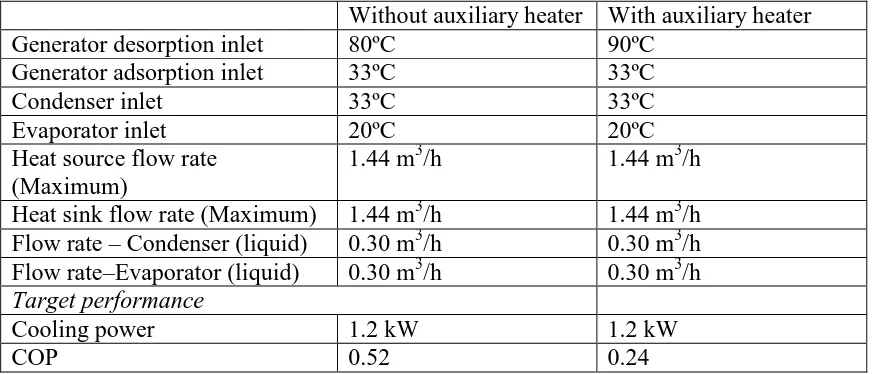
Table 1. System performance specification
Table 2: Generator characteristics
Table 3: Component volumes and masses
Table 1. System performance specification
Without auxiliary heater With auxiliary heater
Generator desorption inlet 80ºC 90ºC
Generator adsorption inlet 33ºC 33ºC
Condenser inlet 33ºC 33ºC
Evaporator inlet 20ºC 20ºC
Heat source flow rate (Maximum)
1.44 m3/h 1.44 m3/h Heat sink flow rate (Maximum) 1.44 m3/h 1.44 m3/h Flow rate – Condenser (liquid) 0.30 m3/h 0.30 m3/h Flow rate–Evaporator (liquid) 0.30 m3/h 0.30 m3/h
Target performance
Cooling power 1.2 kW 1.2 kW
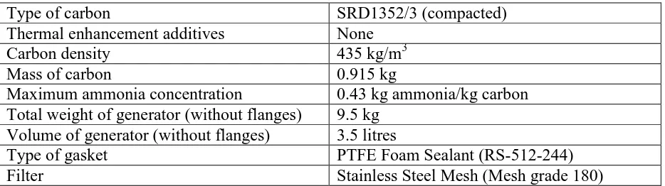
Table 2: Generator characteristics
Type of carbon SRD1352/3 (compacted)
Thermal enhancement additives None
Carbon density 435 kg/m3
Mass of carbon 0.915 kg
Maximum ammonia concentration 0.43 kg ammonia/kg carbon Total weight of generator (without flanges) 9.5 kg
Volume of generator (without flanges) 3.5 litres
Type of gasket PTFE Foam Sealant (RS-512-244)
Table 3: Component volumes and masses
Volume (litres) Mass (kg)
Adsorbent 12 2
Reactor heat exchanger 2 19
Refrigerant Not applicable 1
Sorption reactor total 14 22
Condenser 2 4
Evaporator 1.2 2
Auxiliary equipment 2.7 2
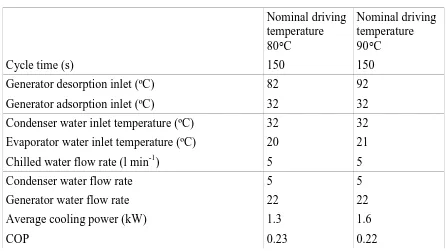
Table 4: Sorption air conditioning system results
Nominal driving temperature 80°C
Nominal driving temperature 90°C
Cycle time (s) 150 150
Generator desorption inlet (ºC) 82 92
Generator adsorption inlet (ºC) 32 32
Condenser water inlet temperature (ºC) 32 32 Evaporator water inlet temperature (ºC) 20 21
Chilled water flow rate (l min-1) 5 5
Condenser water flow rate 5 5
Generator water flow rate 22 22
Average cooling power (kW) 1.3 1.6
List of Figure Captions
Figure 1: Simplified schematic diagram of system within a car
Figure 2: Chemically etched shim
Figure 3: Reactor with one water manifold
Figure 4: Close view of water channels through part of water manifold assembly
Figure 5: Complete sorption generator
Figure 6: Laboratory test rig
Figure 7: Temperature profile during heating/cooling cycles
Figure 8: Adsorbent thermal conductivity identified from the experimental results
Figure 9: Temperature and pressure in a cycle with 90°C driving temperature
Figure 10: Cooling power in a cycle with 90°C driving temperature
Figure 11: Cooling power in a cycle with 80°C driving temperature
Figure 12: Effect of coolant flow rate on the system performance with 90°C driving
temperature
Figure 3: Reactor with one water manifold
Slots for adsorbent
Water channels
0 20 40 60 80 100 120 140 160 180 200 20 30 40 50 60 70 80 Time (s) Tem per at ur e ( o C) Carbon Hot Water In / Cold Out Hot Water Out / Cold In
Robert Critoph is a professor and head of the Sustainable Energy and Engineering Design research group of the School of Engineering in the University of Warwick. He obtained his B.Sc. in Aeronautical Engineering from the University of Southampton in 1972, and was awarded the 1972 Royal Aeronautical Society Prize. His PhD was from the University of Southampton in 1977 and his D.Sc. from the University of Warwick in 2007. He has worked in solid adsorption heat pump and refrigeration systems since 1986.
Steven Metcalf is currently a PhD student and research associate at the University of Warwick's School of Engineering. He gained a first class MEng degree in mechanical engineering at the university in 2004 and received the IMechE best student award. The design of a plate heat exchanger, to which he has made a significant contribution and which was carried out as part of an EU project, has recently been filed with the UK patent office.