A Thesis Submitted for the Degree of PhD at the University of Warwick
Permanent WRAP URL:
http://wrap.warwick.ac.uk/94045
Copyright and reuse:
This thesis is made available online and is protected by original copyright. Please scroll down to view the document itself.
Please refer to the repository record for this item for information to help you to cite it. Our policy information is available from the repository home page.
A NEW
MULTIPLE-ACCESS TELECOMMUNICATION
SYSTEM
Thesis submitted in partial requirement for the degree of Doctor of
Philosophy
University of Warwick
by
Paul Robert Thomas MSc
TABLE OF CONTENTS
List of figures vi
List of tables xi
Acknowledgements xii
Declaration xiii
List of symbols xiv
Summary xv
CHAPTERl Introduction 1
1.1
History3
1.2
Techniques6
1.3
The CV -CCMA system18
CHAPTER 2 Survey of recent research 25
2.1
Introduction25
2.2
Information sources26
2.3
Channel models27
2.4
Multiple-access 'information theory28
2.5
Multiple-access coding32
2.6
Time/frequency division multiple-access34
2.7
CV -CCMA research35
2.8
Code division multiple-access36
2.9
High speed radio digital signal processing38
2.10
Modern digital radio design40
2.11
Summary41
CHAPTER 3 CDMAlCV·CCMA comparative discussion 43
3.1
Introduction43
3.2
CDMA summary44
CHAPTER 3
(continued)3.4
Comparisons48
3.4.1
Capacity49
3.4.2
Power control50
3.4.3
Timing51
3.4.4
Noise52
3.4.5
Multipath propa~ation52
3.4.6
Cost53
CHAPTER 4
Multiple-access capacity limits55
4.1
Single-channel theoretical capacity limits55
4.2
Multiple-channel theoretical capacity limits60
CHAPTER 5
Theory of operation65
5.1
Introduction65
5.2
System synchronisation69
5.3
Receiver processing72
5.4
System simulations74
5.5
Codewords78
5.6
Convolutional coding86
CHAPTER 6
Implementation 896.1
General implementation89
6.1.2
System control90
6.1.3
Synthesisers93
6.1.4
Synthesiser implementation100
6.2
CV -CCMA transmitter implementation108
6.2.1
Input stages108
6.2.2
Speech digitisation110
6.2.3
Implementation115
6.2.4
Transmitter filters118
6.2.5
Radio frequency modulation122
CHAPTER 6 (continued)
6.3. Receiver implementation 128
6.3.1 Front-end circuitry 129
6.3.2 Second stage and mixer 131
6.3.3 Analogue-to-digital conversion 133 6.3.4 Signal processor interface 138
6.4. Software implementation 142
6.4.1 Introduction 142
6.4.2 Software operation 143
6.4.3 Software emulation of receiver
combinational matrix calculations (QPSK) 156
6.4.4 QPSK decode example 158
6.4.5 BPSK combined matrix calculations 162
6.4.6 Summary 165
CHAPTER 7 Results 166
7.1 Introduction 166
7.2 The synthesisers 168
7.3 The transmitters 177
7.4 The receiver 185
7.5 Bit error rate performance 192
7.6 Synchronisation 201
7.7 Summary 204
CHAPTER 8 Conclusions, discussion and further work 205
8.1 Introduction 205
8.2 Coding 206
8.3 Optical systems 207
8.4 Mobile radio 208
8.5 Low-cost radio telecommunications 210
8.6 Military applications 211
8.7 Speech digitisation 213
8.8 Filters 214
CHAPTER 8 (continued)
8.10 General
8.11 Conclusions
REFERENCES
GLOSSARY OF ACRONYMS
APPENDICES
Appendix 1 Texas DSP decode programs
DSK kernel program
Appendix 2 Mathcad pseudo-inverse
calculation program
Appendix 3 Mathcad variation of g simulation program
Appendix 4 Spice results and netlists Appendix 5 12C software, circuits
Appendix 6 87C750 interface
Appendix 7 Phase-locked loop
Appendix 8 Codeword generation circuit
Appendix 9 TMS320C50 filters code
Appendix 10 Maxim modulators data
Appendix 11 Burr-Brown A-D data
Appendix 12 Low-noise block
Appendix 13 Set-up routines for the DSP
Appendix 14 Set-upDSK
Appendix 15 12C output for bypass
Appendix 16 Timing diagrams Tx & Rx
CHAPTERONE
Figure 1.1
Figure 1.2
Figure 1.3
Figure 1.4
Figure 1.5
Figure 1.6
Figure 1.7
Figure 1.8
LIST OF FIGURES
Time division multiplexing
Primary rate time division multiplexing
Frequency division multiplexing
AT & T frequency division multiplexing hierarchy
Code division multiplexing
Code division multiple-access
Space diversity multiple-access
Complex valued collaborative coding multiple-access system
CHAPTER TWO
Figure 2.1 Channel capacity of T -user binary phase shift keying
8 9 10 11 13 14 16 24 31
Figure 2.2 Channel capacity of 2-user binary multi -phase shift keying 31
CHAPTER THREE
Figure 3.1 Typical CDMA handsets
CHAPTER FOUR
Figure 4.1
Figure 4.2 .
Figure 3.3
Bit error probability for multi-phase signalling (coherent M=2k)
Normalised channel bandwidth verses Et/No
Capacity region of 2-user multiple access channel
CHAPTER FIVE
Figure 5.1 QPSK I BPSK phasor plots
Figure 5.2 Codeword generation
CHAPTER FIVE (continued)
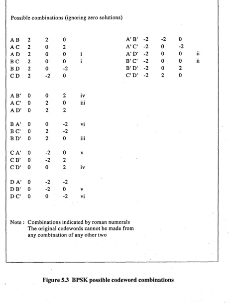
Figure 5.3 BPSK possible codeword combinations 82
Figure 5.4 Block diagram of CV -CCMA demonstrator 85
CHAPTER SIX
Figure 6.1 I2C bus PC interface 92
Figure 6.2
fc
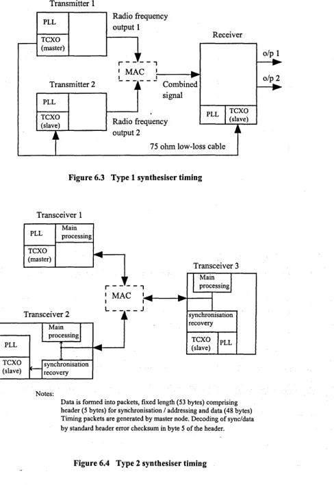
bus microcontroller interface 92Figure 6.3 Type 1 synthesiser timing 96
Figure 6.4 Type 2 synthesiser timing 96
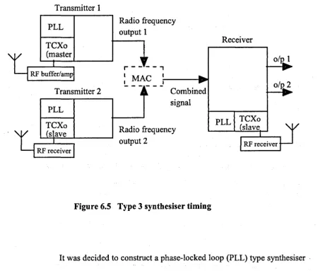
Figure 6.5 Type 3 synthesiser timing 97
Figure 6.6 Basic phase locked loop 99
Figure 6.7 Synthesiser block diagram (simplified) 99
Figure 6.8 Synthesiser output spectrum 104
Figure 6.9 CV -CCMA synthesiser circuit diagram (reduced) 105
Figure 6.10 Inter-integrated circuit bus loading circuitry 106
Figure 6.11 PC386 I2C bus loading circuitry and TMS320C50 filters 106
Figure 6.12 Synthesiser surface-mount printed circuit board 107
Figure 6.13 CV -CCMA transmitter functional 109
Figure 6.14 CV -CCMA demonstrator transmit audio stages 111
Figure 6.15 CV -CCMA demonstrator pattern generator circuit 111
Figure 6.16 Basic Delta modulator /demodulator 114
Figure 6.17 Continuously variable slope Delta modulator/demodulator 114
Figure 6.18 Transmitter codeword generation 117
Figure 6.19 Pulse shape filtering 121
Figure 6.20 Typical pulse shapes/spectra 121
CHAPTER SIX (continued)
Figure 6.22 Codeword generator boards I test pattern generator boards
Figure 6.23 Two transmitters and data load circuitry
Figure 6.24 Low-noise block stripline layout
Figure 6.25 CV -CCMA receiver functional
Figure 6.26 Receiver circuit (reduced)
Figure 6.27 Burr-Brown DSP102 analogue input/digital output
Figure 6.28 Analogue-digital daughter board
Figure 6.29 Receiver 1 in the laboratory at Warwick
Figure 6.30 Receiver filter implementation
Figure 6.31 Pseudo-inverse calculation flowchart .
Figure 6.32 Digital signal processor initialisation flowchart
Figure 6.33 Digital signal processor receiver flowchart (type 1)
Figure 6.34 Digital signal processor receiver flowchart (type 3)
Figure 6.35 Multiplication routines flowchart
Figure 6.36 Sort minimum routine (BPSK)
Figure 6.37 Sort minimum routine (QPSK)
CIIAPTERSEVEN Figure 7.1 Figure 7.2 Figure 7.3 Figure 7.4 Figure 7.5
CV -CCMA Block diagram
S ynthesiser 1, minimum frequency output spectrum
Synthesiser 1, operating frequency output spectrum
Synthesiser 1, maximum frequency output spectrum
CHAPTER SEVEN (continued)
Figure 7.6 Synthesiser 2, operating frequency 176 output spectrum
Figure 7.7 Synthesiser 2, maximum frequency 176
output spectrum
Figure 7.8 Test equipment layout (transmitter) 178
Figure 7.9 Transmitter 1 output spectrum 179
(test pattern 1 input)
Figure 7.10 Transmitter 2 output spectrum 179
(test pattern 1 input)
Figure 7.11 Transmitter 1 : input test pattern 180
Figure 7.12 Transmitter 2 : input test pattern 180
Figure 7.13 Combined output spectrum (test pattern inputs) 181
Figure 7.14 a) Audio test tone input
b) Deltamodulator output (overdriven for clarity) c) Recovered Deltamod I transmitted Deltamod
d) Coder output 182
Figure 7.15 Combined output spectrum with recorded audio
inputs and codeword set 1 (unique set for each tx.) 183
Figure 7.16 a) Audio input test tone b) Deltamodulator output
c) Combined spectrum (input test set 2) 184
Figure 7.17 Receiver test equipment layout (type 1) 187
Figure 7.18 . PC screen showing disassembly of fast5.asm 188
Figure 7.19 Recovered test pattern data (BPSK) 189
Figure 7.20 Recovered test pattern data (QPSK) 189
Figure 7.21 Equipment set-up (University of Warwick) 190
Figure 7.22 Equipment set-up(Cable & Wireless PLC, Coventry) 191
Figure 7.23 Simulation results from [74] 193
Figure 7.24 Simulation(l) from 7.23 redrawn for
CHAPTER SEVEN (continued)
Figure 7.25 Test equipment layout (BER testing) 198
Figure 7.26 Link 1 fixed and link 2 varied 199
Figure 7.27 Link 2 fixed and link 1 varied 199
Figure 7.28 Link 1 varied and link 2 varied 199
Figure 7.29 Test equipment layout (synchronisation testing) 202
[image:11.505.21.496.234.776.2]Figure 7.30 Spectrum of 10 MHz recovered synchronisation 189 signal (type 3 system)
LIST OF TABLES
Table 1.1 Important dates in electronic communications 5
Table 1.2 Collaborative coding - example 1 20
Table 1.3 Collaborative coding - example 2 20
Table 3.1 Forward link channel parameters rate set 1 46
Table 3.2 Forward link channel parameters, rate set 2 47
Table 3.3 Reverse link channel parameters, rate set 1 47
Table 3.4 Reverse link channel parameters, rate set 2 48
Table 5.1 Codewords and modulated output system 1 75
Table 6.1 Synthesiser I2C programming data 102
Table 6.2 Codeword test set 1 summary 159
Table 6.3 Test set 1 summary 163
Table 7.1 Synthesiser programming format 169
Table 7.2 I2C data transmitted (50MHz output) 169
Table 7.3 I2C data transmitted (90MHz output) 170
Table 7.4 I2C data transmitted (100MHz output) 170
Table 7.5 Synthesiser 2,
fc
data transmitted (658MHz output) 171Table 7.6 Synthesiser 2, I2C data transmitted (850MHz output) 172
Table 7.7 Synthesiser 2,
fc
data transmitted (1. 12095GHz output) 172Table 7.8 Lock times for synthesisers 173
Table 7.9 BER results, link 1 fixed, link 2 varied 196
Table 7.10 BER results, link 2 fixed, link 1 varied 197
ACKNOWLEDGEMENTS
I would like to acknowledge the guidance and support given to me by my project
supervisors, Dr Steven Chandler (University of Warwick, now Rural Radio Systems) and
Professor David Hutchins (University of Warwick). I would also like to thank Professor
David Whitehouse (University of Warwick) for his encouragement to get the work started
and Professor Roger Green for his constructive comments.
I would also thank my colleagues at Cable and Wireless for putting up with
me over the last five years, especially Professor David Ashton (Chief Executive - retired)
for allocating me some time to get the work underway, Dr Habib Rashvand (ex-TT & E
lecturer) for his helpful comments, Mark Abbott (ex-TT & E technician) for making the
surface mount circuit boards and Richard Hallows (ex-Head TT & E) for his support.
Finally, my thanks to Alison for keeping our son Harry occupied, allowing me
DECLARATION
This thesis has been written by myself and is based on research undertaken at the •
University of Warwick between 1995 and 2000. The information recorded herein has not
been previously published, except in [18] and [127-130]
All other sources of material are acknowledged and appropriately recorded.
LIST OF SYMBOLS
Symbol Meaning Units
g the phase shift and attenuation occuring between the transmitter and receiver
a mean
c velocity of light (in vacuo) metres per second
f
frequency Hertz or cycles I secondI electrical current Amperes
j square root of -1
t time seconds
v velocity metres per second
V electrical voltage volts
W power watts
= equals
- identical
<
less than> greater than
L
sumA
wavelength metres11
correlation ratio.
therefore..
\:;f all of
E belongs to the set
*
convolutioncr standard deviation
[AJ matrix array
Multiples and sub-multiples used:
m milli 10-3 K kilo 10+3
J! micro 10-6 M mega 10+6
n nano 10-9 G giga 10+9
SUMMARY
This thesis records the research and development work carried out on a new telecommunications multiple-access system called the 'Complex Valued Collaborative Coding Multiple-Access' (CV -CCMA) system. The CV -CCMA system enables more than one transmission to use a communication channel without significant bandwidth expansion. The work has been completed between 1995 and 2000 whilst researching for a (part-time) Doctor of Philosophy degree at the University of Warwick.
The new mUltiple-access system follows the general trend in communication systems that has been taking place over recent years. The reduction in the cost of processing power (million floating-point operation devices are now only a few pounds), has meant that the complex processing components of communication systems have moved from the analogue to the digital domain. Systems once regarded as too expensive to implement (except by the military) are now commonplace. The main digital processing element used for development of the system is a standard floating-point digital signal processor (DSP). A summary of the algorithm developed and software produced is included in this thesis. New techniques were developed to solve the multi-access resolution problems using the DSP and these are presented.
The fundamental theory underlying the CV -CCMA system is described in detail with simplified examples showing the processes involved. A practical two-transmitter, one-receiver implementation was designed and constructed in order to prove the viability of the system, and details of this work are included in the thesis. Computer programs were written to solve the various linear algebraic equations relating to the operation of the decoding algorithm. Simulation programs enabling parameter variation without circuit construction are also recorded in the thesis. Problems encountered with the new circuitry are discussed and the solutions detailed. This includes a new high-stability oscillator that was designed, built, and tested and which was required in order for the system to function properly. Also described is the high-speed conversion circuitry.
A new sequence of codewords has been developed, helping to reduce the stringent requirement on timing and synchronisation, and results are presented. New methods of synchronisation are discussed together with future development of the system. Projections as to possible uses of the system are also presented.
1
INTRODUCTION
As we enter the second century of radio communication the demands on the radio
frequency spectrum are becoming ever greater. The range extends from systems
operating at very low frequency for world-wide submarine communications, to super
high frequency telecommunications systems and direct broadcast satellite services for
commercial use. With the advent ot all these new services, the electromagnetic
communications spectrum is nearing saturation. The usable section of the
electromagnetic communications spectrum is bounded; therefore new techniques and
systems are required to enable further expansion of services. A number of techniques
have been developed which enable multiple-access. This requires the sharing of the
communication bandwidth resource, giving increases in the efficiency of usage of the
available spectrum. Although there are theoretical limits on the amount of
'information' that can be communicated over a given bandwidth, the new techniques
aim to optimise the information transfer, and reduce interference between multiple
users of the same bandwidth. At the present time there are many different contenders
for this already large, and potentially very large, market. However, the circuitry
required to enable most of these systems to operate is fairly complicated and requires
a substantial amount of processing power in order to function. The cost of this
processing power has decreased by orders of magnitude in recent years, and this has
given additional impetus to the commercial exploitation of multiple - access systems.
This thesis records the research, design and development of one such
system, called the 'Complex Valued Collaborative Coding Multiple-Access' system
(CV-CCMA system). The system is demonstrated operating with a single
components designed for the global system mobile (GSM) system, produces a very
cost-effective multiple- access telecommunication system.
The main objective of the research was not just to produce further
simulations of the multiple-access system, varying either a transmission parameter or
some. component part of the coding or decoding process, but also to generate a
hardware demonstrator that would identify any problems which might have been
neglected in simulations. This path was followed because of problems experienced in
communications research in other fields. A lot of simulation-based communication
research is limited in use due to the many additional problems that become apparent
only when the systems are implemented in hardware. This is particularly true in the
telecommunications industry, which uses a lot of relatively old equipment. For
example, Cable and Wireless PLC, the main sponsor of this research, is now over one
and a quarter centuries old. This means that there are systems installed that are quite
ancient, usually costing substantial sums to maintain, and a lot of the newer
technologies need to be able to interface with, and often work alongside, these older
systems. This is the area where many problems have arisen, for example in the
implementation of newer statistical trunk systems with installed trunk transmission
plant. Loading/capacity simulations have shown that the systems should work
perfectly, but in practice the systems do not actually work, requiring further
investment to get them working. Similar problems have been encountered with radio
systems and so it was decided at an early stage to 'prove' the theory with some actual
hardware, and to progress the research by implementation of any new techniques
before advancing the whole system. This meant that the research tended to progress in
time could be utilised effectively. Practical demonstrations were found to be essential,
to verify nothing had been forgotten about in the simulations.
1.1 History
It has been over a century since Alexander Graham Bell transferred 'voice-shaped
currents' over copper wire, thus starting the telecommunications revolution. Early
telephone systems were directly connected to an exchange and then caIIs were routed
manually by switchboard operators. The operator's attention was gained by winding a
handle attached to the telephone, connected to a magneto and generating a large
voltage which rang a beII in the exchange. A similar system is still used today by
dealer systems in the financial sector, called generator-generator signalling, and also
for military field telephone systems. In an effort to stop illicit eavesdropping, an
undertaker in the United States, named Almon B. Strowger, invented an automatic
telephone exchange, which comprised electromagnetic relays linked to a dial on the
telephone, automatically connecting subscribers together. These systems were in use
until the 1970s in the United Kingdom. The next major advance came with the
invention of the transistor by Brittain, Bardeen and Shockley at Bell Laboratories in
the United States, designed for telephone switching and able to switch quite large
currents very rapidly, making the slow and unreliable electromagnetic relays obsolete.
Major advances have followed at an exponential rate and developments in other fields
have been used in the telecommunications industry to gain competitive advantage. For
example, field effect transistors, developed by NASA for the Apollo space program in
the 1960s are now widely used in telecommunications systems. Virtually from the
beginning of electronic communication, over a century ago, the demand for services
continually developed to increase the capacity and reliability of telecommunications
systems. Table 1.1 lists a few milestones with particular relevance to this thesis.
In the last twenty years the telecommunications industry has seen a
number of techniques that enable transmission and reception by a number of users, all
using the same transmission resource. Trunk telecommunications traffic is either
carried over a fibre-optic cable (usually callea a bearer) or over a radio system. The
radio is usually a back-up to the fibre. However, the local loop is often still a twisted
pair of copper cables, with all the associated problems of interference and limited
bandwidth. There are a number of standard techniques to reduce these problems,
enabling the transmission of data, at reasonable rates, over twisted pairs. Modem
telecommunications networks are now completely digital, leading to simple
interfacing with current high-speed digital circuitry and associated cheap processing
power. The CV -CCMA system is a completely digital system for multiple access that
will interface easily with current telecommunications systems.
The last few years have also seen unprecedented growth in data
services, fuelled ,mainly by the explosive, growth of low-cost Internet traffic,
electronic commerce, etc. This trend shows no sign of abating; if anything the rate of
increase is such that within a couple of years, voice traffic will be consigned to a
small proportion of bandwidth carried on the back of data traffic. Anew, low-cost,
radio-based multiple-access system could be used for the implementation of these
new services.
Today, in most of the developed world there is a substantial
telecommunications infrastructure, which has cost thousands of millions of pounds to
install and millions of pounds per annum to maintain. In contrast, the developing
Year Event
1834 Carl F. Gauss and Ernst H. Weber build the electric telegraph. 1838 William F. Cooke and Sir Charles Wheatstone build the telegraph. 1844 Morse demon states the Baltimore and Washington telegraph line.
1846 M. Faraday's 'Thoughts on ray vibrations' form basis for e-m field theory. 1858 The first transatlantic cable is laid, and fails after 26 days.
1864 James C. Maxwell predicts electromagnetic radiation. 1876 Alexander Graham Bell develops and patents the telep_hone.
1883 Thomas A. Edison discovers the flow of electrons in a vacuum, called the 'Edison effect' providing the foundation of the electron tube.
1885 Edward Branly invents the 'coherer' radio-wave detector. 1887 Heinrich Hertz verifies Maxwell's theory.
1894 Oliver Lodge demonstrates wireless communication over 150 yards. 1897 Guglielmo Marconi patents a complete wireless telegraph system. 1900 Guglielmo Marconi transmits the first transatlantic wireless signal. 1904 John A. Fleming invents the vacuum tube diode.
1918 Edwin H. Armstrong invents the superheterodyne receiver circuit. 1927 H. Black develops the negative-feedback amplifier at Bell Laboratories. 1933 Edwin H. Armstrong invents frequency modulation.
1935 Robert A. Watson-Watt develops the first practical radar. 1937 Alex Reeves conceives pulse code modulation (PCM).
1947 Walter H. Brittain, John Bardeen, and William Shockley devise the semiconductor transistor at Bell Laboratories.
1948 Claude E. Shannon publishes his work on information theory. 1950 Time-division multiplexing is applied to telephony.
1950s Microwave telephone and communication links are developed. 1953 The first 'multiple-access' transatlantic cable (36 channels) is laid. 1960 Theodore H. Marman produces the first successful laser.
1963-66 Error-correction codes and adaptive equalization for high-speed error-free digital communications are developed.
1965 The first commercial comms. satellite, 'Early Bird', is placed into service. 1966 Kao and Hockham publish 'The principles of fiber optic communications'. 1971 Intel Corporation develops the first single-chip microprocessor, the 4004. 1976 Personal computers are developed. X25 Packet delivery standardised. 1979 64-Kbit random access memory launched.
1981 mM PC is introduced. De-nationalisation of United Kingdom Post Office. Cable and Wireless partial privatisation. Falcon (Mercury) launched by Cable and Wireless as a competitor to British Telecom.
1984 First generation cellular telephones introduced to UK (Cellnet + Vodafone, BT - Securicor and Racal Electronics).
1988 Global system mobile launched in Europe.
1990s Texas DSP chips increase processing power by orders of magnitude. 1990s Explosive growth in Internet usage alters dynamics of telecom. networks.
Mobile penetration is greater than fixed line in some European states.
major investment program to cable them up. For example, it cost Cable and Wireless
PLC over one hundred million pounds to put a basic digital trunk network into Latvia,
a small country with a fair amount of infrastructure already in place, and with most of
the population concentrated in one city. This investment will take many years to
repay. This is another area in which a cheap multi-access radio system, such as
CV-CCMA, will find a ready market, specifically for high density flow-cost access, and
low-density flow-cost access. This thesis will describe the possible implementation of
the CV -CCMA system on existing low-cost rural access radio systems; this work is
briefly covered in Chapter 8.
1.2 Techniques
It is standard practice in telecommunication networks for the electrical representation
of speech to be first digitised by the process of pulse code modulation (PCM), a
technique invented by Alex Reeves in 1937 [1] whilst working in Paris at the IT & T
laboratory and patented by them in 1938. Some of the technology was used in the
early radar systems to detect aircraft. After the war the process was further developed
by the AT & T laboratories in the United States. However, the technique only became
popular commercially with the advent of cheap semiconductor circuitry. The
International Telecommunications Union has standardised the process of PCM with a
series of recommendations, 0701, G703, etc. [2], which have been adopted on a
world-wide basis. In the G series of recommendations the process is defined briefly;
the speech waveform is sampled at 8000 per second, and to comply with the sampling
theorem the speech waveform is band-limited to 300-3400 Hz. Each sample is then
converted to an 8-bit binary code. The code consists of a sign bit and 7 amplitude bits;
conversion is not direct; it is non-linear or logarithmic. The audio input is assumed to
be standard speech so more 'bits' are assigned to the lower-level signal amplitudes
than to the higher ones. The process approximates the output I input transfer function
to a logarithmic law and two world-wide standards have evolved, the 'J!' law in the
United States and the 'A' law in the rest of the world (conversion circuitry is needed
between the two standards). There are 8 bits output for each sample taken 8000 times
per second, giving a digital output rate of 64 Kb/s, or 32 Kb/s with Adaptive PCM, an
adaptive predictive technique defined in 0732.
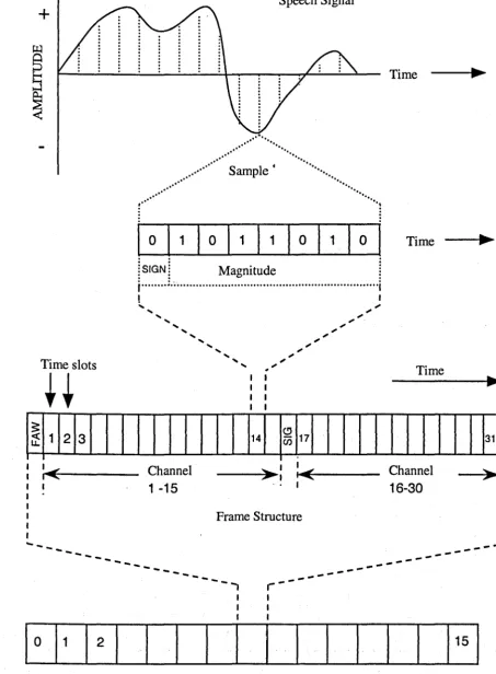
These digitised streams of audio information are then combined
together with other digitised traffic, data or encoded video, by a process called time
division multiplexing (TDM). Each digital input is buffered and assigned a period in
the time domain called a time slot. The time division multiplexer then combines these
inputs and outputs them, at a higher rate, together with synchronisation and signalling
information. Figure 1.1 illustrates the concept of TDM and Figure 1.2 shows a
standard primary rate 30 channel (2 Mb/s or S-bearer) roM in operation, used
throughout the world as the first level of mUltiplexing. The multiplexer's output
aggregates are then combined with other mUltiplexer outputs, giving (currently)
defined data rates up to about 10 ObIs. The TDM process is now a mature technology,
with international standards set by the International Telecommunications Union
enabling the world-wide inter-connection of systems operating to these standards.
The main problems arise with synchronisation and management of the
links. If synchronisation cannot be guaranteed then buffers must be used at the
interfaces which causes delay problems, particularly with speech. The other problem
.
with TDM is that the system does not allow for instant access; the transmitter must
of transmission time, requiring buffers, and inefficient. Speech is time-critical, and so
it becomes inefficient to assign a time slot, whether it is required or not. Data tends to
be less time-critical, so queuing can be successfully applied. Recently, adaptive or
statistical TDM systems have become popular, for example asynchronous transfer
mode (ATM), especially with the larger telecommunications commercial operators.
These systems work by dynamically assigning bandwidth on the trunk only when it is
required, giving much higher efficiencies. Statistical systems are also more flexible.
They can be used to implement quality of service parameters, required for today's
multimedia systems. Most importantly, time-critical signals (speech and video) can be
combined with non-time-critical signals (data) and passed over the same trunk
network. The carrier's network can always be fully loaded, which means the carrier
generates as much revenue as possible. As well as the benefits of flexibility the
advantage to the user is mostly in cost reduction, rather than any fundamental
improvement to quality of service.
Amplitude
AI"
user user user user user
1 2 3 4 5
Time
Speech Signal
[image:25.508.34.488.36.653.2]+
...
.
' '.
... ··· ....
~amPle
•...,,- ",
o
1 1 0 1_,0I
: SIGN: Magnitude
j ... ;.; ...
···1
! I
...
:<~____
Channel---~~~:
~:~~---....
_----
---
---1 ----15
---' . I
Frame Structure
---
")I I I
I - -
---I
I I
Multiframe Structure
---Figure 1.2 Primary rate time division mUltiplexing
Time
Time
Channel
16-30
---
---
---~I I
I
I
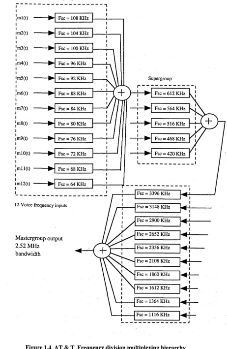
---The aggregate signals are then converted using frequency conversion
techniques and combined in the frequency domain (FDM - frequency division
mUltiplex or WDM - wavelength division multiplex); the translation may be up or
down. The input signals are assigned to a band of frequencies and passed over the
transmission link. In the case of the fibre-optic trunk cable transmission, these
wavelengths are limited to the precisely defined boundaries of the low-loss window,
and the line width of the laser transmitters and photodiode receivers. These techniques
are generically called dense wavelength division multiplexing (DWDM), and current
operating practice gives a maximum of twenty carriers each operating at data rates of
2.5 ObIs (STM-16 rate with adaptation).
Current radio systems operate at maximum data rates of 140 Mb/s within various frequency bands up to 500Hz. Figure 1.3 illustrates the concept of
frequency division multiplexing and Figure 1.4 illustrates the AT & T standard FDM
hierarchy, still in use throughout the world, although now declining in popUlarity.
Amplitude
n
user user user user
1 2 3 4 Frequenc y
r '
First level group
.---,
1 1
:ml(t) Fsc = 108 KHz 1 - - _ ... 1 _ - . , 1 1 1m2(t) 1 I :m3(t) 1 I Im4(t) 1 I Im5(t) I 1 :m6(t) 1 I Im7(t) I 1 :m8(t) I I Im9(t) I 1 Fsc= 104KHz
Fsc = 100 KHz
Fsc =96 KHz
Fsc=92 KHz
Fsc = 88 KHz
Fsc= 84 KHz
Fsc= 80KHz
Fsc =76 KHz
ImlO(t) Fsc = 72 KHz I
I
:mll(t) Fsc = 68 KHz I
I
Supergroup
r---I
t-~ __ ~ Fsc = 612 KHz :
-r--~ Fsc = 564 KHz
- ... --~ Fsc = 516 KHz
Fsc=468 KHz
1 Fsc = 420 KHz 1
1 1
L ____________ I
ImI2(t) Fsc = 64 KHz I---~--,.I _ _ _ _ _ _ _ _ _ _ _ _ _ _ •
1 ~----~ 1
1
---~ 12 Voice frequency inputs
Mastergroup output 2.S2MHz
bandwidth
r - - , - - - t Fsc = 3396 KHz
,....,r---f Fsc = 3148 KHz
Fsc = 2900 KHz
Fsc = 2652 KHz
I
1 ~I
~ _ _ _ _ _ _ _ ~ 1
1
\--1r----I Fsc = 2356 KHz
Fsc = 2108 KHz
Fsc = 1860 KHz
Fsc = 1612 KHz
~~--f Fsc = 1364 KHz
I
I 1
[image:27.506.37.499.20.728.2]'---+---1 Fsc = 1116 KHz : !.. - - - -.- _ - _ - _ ____ J
A third technique for access is called code division
multiple-access (CDMA). There are two main types which mostly follow generic algorithms.
The first type is called frequency hopping (FH) CDMA and is a system that modulates
the signal onto carriers whose frequency is selected from a sequence or randomly.
Slow PH is where the hopping rate is less than the information rate and fast PH is
where multiple hops are used for each information bit. Bit interleaving is used as well
as error-correcting codes to overcome some of the fading problems inherent to the
system. These frequency-hopping systems are mainly used by the military and users
requiring high levels of security.
The second type is called direct sequence (DS) and in this system the
individual users are assigned sequences that are separated from one another by the use
of a set of nearly orthogonal waveforms or sequences. These are often referred to as
spreading codes because they cause the output bandwidth to spread. Due to the nearly
orthogonal nature of the sequence when they are combined together, assuming they
are properly synchronised and with no errors, the cross-correlation between different
users will be nearly zero.
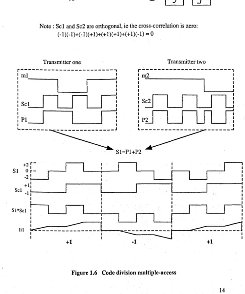
A number of different transmitters can then be overlaid using the same
bandwidth providing they are using distinct sequences. The receiver multiplies the
composite signal by the same orthogonal sequence as the required transmitter,
producing an output which is integrated over a bit period to give the recovered data.
Note that the mUltiplication of the signal by the orthogonal sequences produces an
increase in bandwidth, and drop in efficiency: the signal is 'spread'. Figure 1.5 shows
a simplified representation of code division multiple-access, and Figure 1.6 shows a
block diagram of a typical spread spectrum system. The technique is derived from a
block a signal that has a wide bandwidth, without using large amounts of power.
CDMA is more complex than the other techniques described for multiple-access and
has a number of unique problems associated with it. Some of these problems are
described in Chapter 3. The near-far problem, in which strong DS signals swamp
weaker DS signals, requires quite complicated power-control circuitry to be
implemented in DSCDMA systems. Also the coherence bandwidth must be less than
the spread bandwidth, and this may be 10 MHz for small-room operation, and far in
excess of this for satellite operation.
Amplitude
Code
user 1 '
Time user 2
user 3
user 4
user 5
.---j
--1 __ t ________ , User 1 :
.---1 __ ! ________ User 2 :I
Frequency
Frequency Hopping
Direct Sequence
Frequency
message 1
+1-1 +1
Tf
It!J
(ml)PI
ml Integrator Squarer
spreading code 1 ScI
-1 -1 +1 +1 (ScI)
spreading code 2
-1 +1 +1 -1 (Sc2) Sc2 message 2
Integrator Squarer
+1 +1-1 m2
(m2)
..
Tf
It2J
P2
Note: ScI and Sc2 are orthogonal, ie the cross-correlation is zero: (-1)( -1)+(-1)(+ 1)+( + 1)(+ 1)+(+ 1)(-1) = 0
Transmitter one Transmitter two
r---,
mlr---1
---.
ScI _ - - J
PI _ - - J
L.. _ _ _ _ _ _ _
2r
-+ 1
SI 0
r-21
- 1 - 1 - - . 1
+1
ScI -I ~ _ _ _ ---J
SI=Pl+P2
m2 1
1 1 1 1 1 1 1
---_
.... 1 11 I 1
I I 1
I 1 1
SI*ScI
I
:
:
I :
1
I
I
U
I....--.-J:
It!
r--n-.::::=.-n--l--~nn-31-, --~---:::J
[image:30.525.20.520.196.795.2]+1
·1 .+1
A more recently developed multiple-access system, which is popular in
the local area network (LAN), is the collision detection carrier sense multiple-access
(CDCSMA) method. This is a variation of the time division multiplex (TDM) systems
already described, generically called statistical TDM. In this system the access
channel is sensed for activity and the transmitter output is buffered until a gap appears
in bus activity when it can transmit its data. Weaknesses of this system are the lack of
instant access, particularly when the network is busy, and the complexity of the sense
circuitry. However, the system is cheap and is now very popular.
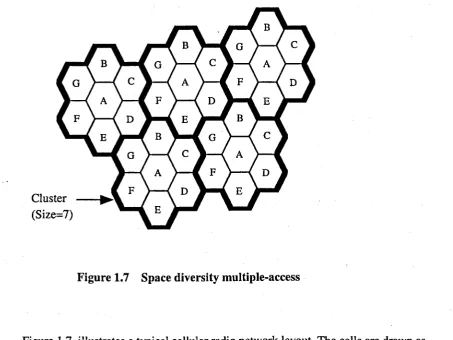
Another technique of multiple access is the space diversity
multi-access (SDMA) system, mainly used with radio or optical systems. In these systems
the network is subdivided into geographical areas, thus ensuring the transmitters and
receivers operating on the same frequencies are always physically more than a certain
distance apart. This distance is sufficient to stop interference between the systems
because the attenuation on the signal drops it below the interfering threshold value. It
is usual to employ different polarisation in the signals in an effort to reduce further
any interference. This method is used in cellular radio systems with the same
frequencies re-used in cells, but only when they are a minimum distance apart. Figure
1.7 illustrates the concept of SDMA. There are many problems with this simple
system as radio propagation is very variable and the signals may propagate
substantially further than intended, under certain atmospheric conditions. This causes
problems with multiple cells both being accessed and the possibility of dropped calls.
Another problem is that, at the higher frequencies, the waves propagate along
overhead lines (power I rail feed, etc.), which act as waveguides and may lock into or
interfere with a cell a considerable distance away from the transmitter. The network
Cluster (Size=7)
Figure 1.7 Space diversity multiple-access
Figure 1.7 illustrates a typical cellular radio network layout. The cells are drawn as
hexagons and the letters A-G represent the group of frequencies that are used
within a cell. Note that coverage area is only approximated by a hexagon. At the
edge of coverage, where geographical features cause problems, directional aerials
are used to prevent interference. The system is easily combined with one (or
more) of the other multiple-access techniques already discussed. Note also that
Figure 1.7 shows a frequency re-use factor of 7 and that there are always at least 2
cell diameters between cells that are using the same frequencies.
All of the systems described thus far combine the individual signals
in a common medium, usually silica glass-fibre, copper co-axial cable or the radio
producing mathematical models of various different types of channel. The model used
in this thesis is the adder channel with discrete input and output [4-12]. The other
channel models used are detailed in Chapter 2, the research survey section of this
thesis. A lot of the work in these papers is related to the theoretical maximum data
rates that the multiple-access channels can accommodate. The individual transmitters
and receivers are treated as independent units, which in the case of the implemented
.
. CV-CCMA system is not strictly true, as the components of the system need to be
synchronised in order to function. For further discussion on the channel, including the
effect of feedback and interference, see Chapter 2. Some work was done on a
performance comparison between CV -CCMA and COMA. This used a rather more
complicated model of a mobile radio channel with different types of noise and fade I
synchronisation loss (from [3]); see Chapter 3 for details.
To summarise, there are three other multiplex technologies, FDM,
COM and TOM. The fact that only a subset of a number of users wish to
communicate at a time enables sharing of a channel between them; there is no need
for each user to be allocated a permanent bandwidth. The larger the number of users
that can share resources the larger the statistical gain possible. TOM often uses a
multi-access protocol to partition time slots dynamically, e.g. COCSMA.
COMA uses near orthogonal sequences and so long as no more than a
number proportional to the number of orthogonal channels are in use at anyone time,
error-free transmission is possible. This makes COMA ideal for statistical
multiplexing. FDM cannot easily be made to handle dynamically varying
transmission rate requirements, with each user allocated its own frequency channel.
All of the multiple-access systems described are limited in
all the systems. The relative advantages and disadvantages of the different systems lie
in the ease of use, or otherwise, when used as part of a complete multiple-access
system. Within the telecommunications field, the ability to interface with existing
(legacy) systems is probably one of the most important considerations.
1.3 The CV -CCMA system
In 1994 work was started at Warwick investigating new multi-access techniques with
specific application to the telecommunications industry, particularly satellite
communications and digital mobile telephones. These are two very important areas of
interest to the candidates employer, Cable and Wireless PLC. It was decided that the
'Complex Valued Collaborative Coding Multiple-Access' (CV-CCMA) system
offered the most promise for development as a new multi-access radio technique. The
work was developed from discussions with Dr Steve Chandler at Warwick, which
indicated that ordinary collaborati ve coding techniques were impractical for use over
a radio channel.
It was decided to develop the CV -CCMA system as a digital radio
system using digital signal processing techniques with spatial diversity. This would
enable simultaneous reception of a number of superimposed signals within the same
bandwidth and without the use of spreading. The system can increase the capacity of
telecommunication systems, particularly satellite and digital mobile telephones,
providing significant performance improvements over other multiplexing and
multiple-access techniques.
CV -CCMA is inspired by the technique of collaborative coding,
which, though theoretically interesting, was not practicable for use on radio systems
Collaborative coding is based on the superposition of two signals from different users,
producing a combined signal which can be decoded to recover the original signal
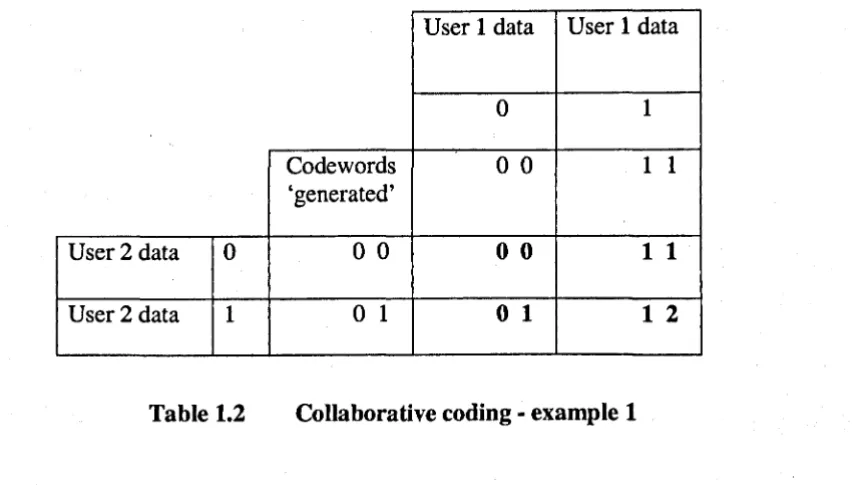
transmissions. The system is best explained with the aid of a simple example. Assume
we have two transmitters and one receiver with the transmitters programmed to output
codewords as below.
Transmitter 1:
'0' = 0 0
'1'=11 ('Data input'
=
codeword output)Transmitter 2:
'0' =00
'1'=01 ('Data input'
=
codeword output)The codewords can be modulated by superimposing onto a radio
frequency or optical frequency carrier as a varying amplitude level. Note that the
combining channel is assumed to be a simple adder channel, that is each component
bit is added to the corresponding bit from the other transmitter. The system is
assumed to have ideal synchronisation, so both bit and frame timing are ideal. The
User 1 data User 1 data
0 1
Codewords
o
0 1 1'generated'
User 2 data 0
o
0o
01 1
[image:36.531.53.485.40.282.2]User 2 data 1
o
1o
1
1 2
Table 1.2 Collaborative coding - example 1
The bold figures indicate the allowed codeword combinations; thus, if we receive any
one of the four combinations the original transmitted data can be recovered as it is a
unique solution to the addition of the original collaborative codes. Also of note is the
fact that, even with the simple two-user example described, the channel is loaded at an
efficiency of 1.0 bit per baud, as each user runs at 0.5 bitlbaud giving 1.0 when added.
Table 1.3 shows how this can be extended to obtain better efficiencies.
User 1 data User 1 data
0 1
Codewords
o
0 1 1'generated'
User 2 data a
o
0o
0
1 1
User 2 data b
o
1o
1
1 2
User 2 data c 1 0
1 0
2 1
Note that all the states (in bold) are still uniquely decodeable. The
codewords shown give an efficiency of approximately 1.3 bits per baud. Work has
been carried out on the efficiency of collaborative codes [13] setting out the
definitions for capacity boundaries on these efficiency measures.
The system is quite simple and elegant, requiring accurate timing and
an adder channel between the transmitters and receivers. However, in the case of
radio transmission, there will not be an ideal adder channel between the transmitters
and receivers, but an attenuation and a phase shift (called the g value). This g value
may be variable, particularly if the systems are mobile. This means that in order to
resolve the combined signals an accurate timing relationship between the transmitters
and receivers is required. The receivers will be pre-programmed with all the
transmitted codewords. Then, using the processing power of the digital signal
processor, the original transmissions can be resolved. The receiver can resolve the
phase shift, the attenuation and the transmitted codewords simultaneously. This now
becomes a CV -CCMA system. The operation of the system is covered in detail in
Chapter 5.
Following the logic of the argument, even if some of the combined
codewords are theoretically identical, provided they are received over different paths
involving different attenuations and phase shifts, then the original codewords can be
reconstructed. This is because the signals are multiplied by the attenuation and phase
shift, and they are different for each path. This is the principle of the first of the
CV-CCMA systems to be designed and built at Warwick.
Previous research, (into radio multiple-access), has produced a number
of proposed techniques designed to resolve the individual transmissions of a
Multiple Access (CCMA) system. The receiver incorporated an estimation technique
based on the gradient descent algorithm [15,16]. This, together with a predictor and
corrector, was proposed as a receiver, with the capability of resolving multiple signals
within the same bandwidth. The CV -CCMA system differs from this serial approach
in that the g values are simultaneously estimated with the data values.
The basic algorithm of CV -CCMA is sufficiently computationally
. efficient to enable implementation of a system, with realistic data rates, using a
standard floating-point digital signal processor. This is a major advance because the
previously proposed advanced systems for co-channel interference suppression or
simultaneous demodulation of superimposed signals have required large and
expensive amounts of processing.
The CV-CCMA system does not separate the individual inputs to the
MAC (multiple-access channel) in terms of frequency or time but assigns unique
collaborative codes to each user. These codewords are unique to each transmitter and
in the first practical implementation are all linearly independent [17]. The
pre-calculated combined matrices, necessary for correct receiver operation, are stored in
the receiver memory. The receive process then proceeds by calculating the minimum
Euclidean distance between the received vector and the pre-calculated codeword
combination. The recovered data is then output using a simple look-up table. The
system is simpler in implementation than CDMA and without the need to 'spread' the
output signal. The two systems are compared later in the thesis but there are
advantages and disadvantages to each. CDMA is substantially more complicated in
implementation but both systems require accurate timing in order to work.
The requirement for linearly independent codewords to be used at each
investigating this problem [18] at Warwick. It was shown that for unique decodability
a less restrictive set of rules could be implemented. Details of this work are discussed
and included later in this thesis. The simulation programs that were written, and the
actual hardware constructed, were designed for ease of experimentation with
codeword variations. Figure 1.8 illustrates the system concepts in a block diagram of
a basic CV-CCMA system.
This introduction has described in simple terms some of the systems
and techniques the CV-CCMA has been designed to improve upon, and work with, in
the modem digital telecommunications industry. The system has known limitations,
for instance the fact that perfect timing is assumed and the problems of multi path,
which have yet to be addressed; the latter could be resolved but this would
substantially increase the complexity of the system, as is the case with most radio
systems. The issues raised in this introduction are discussed and expanded upon in
later chapters. The thesis also records the work done to demonstrate the viability of
the system. If the system were not viable there would be no point in solving the other
issues. The thesis also develops some of the ideas generated during the research. For
example, once the g values are determined they can be used to decode the mUltiple
transmissions, as they are unique to each path. This removes the need for codes,
timeslots or frequencies dedicated to each user.
The next chapter records a survey of recent research into the
Input 1
Input 2
Transmitter 1
r---Buffer + Radio
..
collaborati ve..
frequency.
....
...
code generator modulator
- - - _ _ _ _ _ _ 1
Transmitter 2
r---Buffer + Radio
...
collaborati ve...
frequencyI
....
~code generator modulator
- - - ______ 1
Receiver
,
V-,
V
r---TMS320C31 Precision Radio
Floating point analogue - frequency
signal digital de-modulation
processor convertor
olp 1 olp 2
gl
= Rl+jXl
g2
= R2+jX2
~ I
\
,
\
,
~
,:
2
SURVEY OF RECENT RESEARCH
2.1 Introduction
The introductory chapter to this thesis gave a flavour of the different systems
currently in use in the multiple-access telecommunications area. Whilst researching
the thesis it became apparent that different people / companies and institutions
interpret the term 'multiple-access' in different ways.
The more theoretical research encompasses the mathematical
foundations of the multiple-access channel. This area is quite active and has produced
a number of interesting papers, usually based on fundamental information theory
papers, which have been adapted and advanced into the digital age. In the
telecommunications industry the term multiple-access is common to a number of
different systems: time division multiple-access - used in trunk multiplexing
equipment; frequency division multiple-access - used mainly in satellite
communications and high-capacity fibre-optic systems; code division multiple-access
- used in mobile telephone systems; space division multiple-access - also used in
mobile systems and carrier sense/collision detect systems which are mainly used in
local area networks. There are fundamental restrictions to all the systems and each has
advantages and disadvantages over the others. The more commercially orientated
research mostly pushes the already established advantages and disadvantages of each
system forward in the same direction.
In the military area, multiple-access communications are a 'hot' topic,
but it is difficult to investigate this field, as a lot of the material is restricted and not
available to the general public. However, useful research was done by investigating
The initial research carried out revealed a vast amount of information
in the multiple-access field. This has been filtered down to material specifically of
interest and relevant to the work recorded in this thesis.
2.2
Information sourcesThe Institution of Electrical Engineers (lEE) [19] and the Institute of Electrical and
. Electronic Engineers (IEEE) [20] have proved to be a source of much material. The
IEEE runs a communications society [21] and publishes Communications Monthly,
containing interesting and up-to-date material. The lEE publishes Electronic Letters
[22] and Proceedings- Communications [23] also containing much information. The
most productive searching was done manually, searching the 'Inspec' documents of
key abstracts in telecommunications research; these are produced monthly by the lEE
and contain short abstracts of current research publications. The electronic search
engines tended to miss information. One problem with both institutions has been a
financial one. The cost of material is cheaper when requested from an academic
institution than if your request originates from a commercial organisation.
The University of Bath database BIDS [24] was found to be very
useful as were the Cable and Wireless [25] and British Telecom (BT) [26] databases
of current research and state-of-the-art material references. The BT technical journals
were also quite enlightening [27]. University libraries at Cambridge, Southampton,
Sussex and Lancaster were found to contain useful research material, as well as
Warwick.
A number of companies sponsor research into multiple-access
techniques, and these companies publish some very useful material. The Qualcomm
network-loading calculations that were used in the later comparison work. The
American company, Hewlett-Packard [29], produces a number of technical briefs and
technical references, which can be ordered over the Internet, although many are not
published in an electronic format. These were very useful in the radio frequency
design stages, especially when problems were encountered with the modulators. The
Dutch company, Philips [30], produces a wealth of literature relating to their
.
. semiconductors and microcontrollers, most of which is accessible electronically over
the web. Philips sponsors a centre of excellence at Warwick and generously supplied
a lot of equipment and reference material, particularly useful with the design and
implementation of the synthesiser, control circuitry and frequency-conversion stages
of the transmitters and receivers. The American company, Texas Instruments (TI),
produces the digital signal processors that are used in the system. There are two main
web sites and a data base, which can be accessed via [31], containing a lot of
information that was very valuable when trying to get the various routines working.
The company sponsors certain universities and Warwick was enrolled into the
European scheme. This meant hardware and software could be bought at substantial
reductions. Analogue Devices [32], Harris Electronics [33] and National
Semiconductor [34] all had useful websites and integrated circuits were used from
these manufacturers on the strength of the data placed at these sites.
2.3
Channel modelsMost of the work recorded in this thesis treats the information-carrying channel as an
adder channel with discrete input and output. This provides the closest model to the
actual situation in the CV-CCMA demonstrator. In the demonstrator the channel has
used to model the multiple-access channel are: logical OR [35-37]; logical XOR [38];
logical AND [39-40]; collision [41-43]; and switching [44].
2.4
Multiple-access information theoryA good starting point when researching information theory is the seminal paper
written by Claude Shannon in 1948, 'A mathematical theory of communication' [45] .
. This paper derived the formula for the capacity of a channel (C bits/sec), with additive
white Gaussian noise power (N watts), in terms of signal power (8 watts) and
bandwidth (Whertz):
bits/sec ... (1)
This is for a single channel. So if we have multiple transmitters and receivers
occupying the same channel, then if one occupies all the bandwidth and power the
other must be zero. Therefore there must be definable bounds to equate these limits
together. Shannon looked at this problem in 1957 at a symposium at Berkeley, in a
paper entitled 'Two-way communication channels' [46] and defined these bounds for
different codes.
Further work was done by Bergmans and Cover [47] in 1974, showing
that several transmitters operating in an additive white Gaussian noise environment (N
watts) can send at rates (R, bits/sec) strictly dominating time multiplex and frequency
multiplex rates. This is done by the use of a superposition scheme that pools the time
(T, secs), bandwidth (W, hertz) and power (P, watts) allocation of the transmitters. For
bandwidth allocated to each transmitter, and ~
=
P/P, i=
1,2, the fraction of thetotal power, then:
... (2)
For time division multiplexing, where T is the division in time, Pj is the power of
transmission during communication to user i and Ai = TjP/P, then:
... (3)
The two sets of equations, (2) and (3), illustrate the duality between time and
frequency mUltiplex. The two can be considered equivalent if time variations in input
power are allowed in time multiplex and spectral variations of power are allowed in
frequency multiplex. Several other papers summarise the findings of researchers in
the field. Wyner [48] summarises very concisely research up to the mid-seventies and
van der Meulen [49] continues in a similar vein. The IEEE Information Theory
Society published a selection of reprint papers in 1994 [50], which contains a lot of
interesting material based around multiple-access communications. Bringing the
research up to date is a paper by Verdu [51] summarising most of the work done over
the last 50 years, including 440 references.
A number of papers appearing in the summaries just described are
relevant to the CV -CCMA system of multiple-access. A broad spectrum of material is
capacity region of multiple-access channels, broadcast, relay, etc., for all achievable
rates. Following on is the paper by van der Meulen [53] which looks at capacity limits
for multiple-access channels and amalgamates a lot of work. Especially interesting are
the comments on asynchronous and quasi-synchronous multi-access channels.
Another paper which contained a lot of interesting information was
written by W. Lee [54] in 1990 and concerns the channel capacity in a Rayleigh
. fading environment, the type of environment in which the CV -CCMA system would
have to operate in a mobile telecommunications network. The channel capacity in a
Rayleigh fading environment is derived and shown to be always lower than the
Gaussian noise channel, a 33% reduction at 10 dBm average power but only a 11 %
reduction at 35 dBm average power. He also shows that a diversity scheme can bring
the channel capacity up and that the average channel capacity with Rayleigh fading
equals the channel capacity over a Gaussian noise channel when the bandwidth
approaches infinity. Summarising:
(~)
= log, e.e-io(
-E+lnr+~)
bitlsecIHz... (4)
where (C) is the average channel capacity, B is the bandwidth, ris the power and E is the Euler constant. Note the channel capacity in a Rayleigh environment is an
average value. Extrapolating these results to the multi-access channel was achieved by
Ali [55] in 1991 who based his work on the previous work described and the work of
Ni and Honary [56]. He produced two charts illustrating the capacity limits when
operating in a flat Rayleigh fading environment with additive white Gaussian noise.
These diagrams are reproduced as Figures 2.1 and 2.2, and represent binary phase
4.'
I
10 SNR(dB)
I 20
I
30
- - : Gaussian Channel·--·-- : Rayleigh Fading Channel
I
40
Figure 2.1 Channel capacity of T -user binary phase shift keying
- - : Gaussian Channel •••• - : Rayleigh Fading Channel