Coupled Vibration Analysis of Vehicle-Bridge System
Based on Multi-Boby Dynamics
Deshan Shan, Shengai Cui, Zhen Huang
Bridge Engineering Department, Southwest Jiaotong University, Chengdu, China Email: [email protected], [email protected], [email protected]
Received January 14,2013; revised February 14, 2013; accepted February 21, 2013
Copyright © 2013 Deshan Shan et al. This is an open access article distributed under the Creative Commons Attribution License, which permits unrestricted use, distribution, and reproduction in any medium, provided the original work is properly cited.
ABSTRACT
For establishing the refined numerical simulation model for coupled vibration between vehicle and bridge, the refined three-dimensional vehicle model is setup by multi-body system dynamics method, and finite element method of dy- namic model is adopted to model the bridge. Taking Yujiang River Bridge on Nanning-Guangzhou railway line in China as study background, the refined numerical simulation model of whole vehicle and whole bridge system for cou- pled vibration analysis is set up. The dynamic analysis model of the cable-stayed bridge is established by finite element method, and the natural vibration properties of the bridge are analyzed. The German ICE Electric Multiple Unit (EMU) train refined three-dimensional space vehicle model is set up by multi-system dynamics software SIMPACK, and the multiple non-linear properties are considered. The space vibration responses are calculated by co-simulation based on multi-body system dynamics and finite element method when the ICE EMU train passes the long span cable-stayed bridge at different speeds. In order to test if the bridge has the sufficient lateral or vertical rigidity and the operation stability is fine. The calculation results show: The operation safety can be guaranteed, and comfort index is “excellent”. The bridge has sufficient rigidity, and vibration is in good condition.
Keywords: Cable-Stayed Bridge; Coupled Vibration; Co-Simulation; Multi-Body System Dynamics; Finite Element Method
1. Introduction
Yujiang River Bridge is a large-span double-pylon steel truss cable-stayed railway bridge with double cable plane and double track which is located on Nanning-Guang- zhou high-speed railway line. It is the most convenient railway from Guangxi Province to Perl River Delta ac- cording to the Eleventh Five Year Plan of China Rail- ways. The span combination of main bridge is 36 m + 96 m + 228 m + 96 m + 36 m, and the total length is 492 m. The maximum designed speed is 250 kilometers per hour, and the distance between track centers is 4.6 m. And the design live load is C-live load. One hand, the higher run- ning speed of vehicles makes the coupled vibration be- tween high speeded trains and bridge structure is more noticeable. On the other hand, because of the high flexi- bility, the cable-stayed bridge has lower rigidity com- pared to common bridge [1,2]. So it is necessary to have a coupled vibration analysis of vehicle-bridge system for Yujiang River Bridge, and then the safety and comfort of vehicle running is evaluated based on the analysis results. For meet the current requirement of the refined analysis
for the vehicle-bridge coupled vibration system, the re- fined dynamic model of the whole vehicle is set up by the multi-body system dynamics methods. And the dy- namic analysis model of the bridge is established by fi- nite element method. Finally, the co-simulation method based on multi-body system dynamics and finite element method is adopted to calculate the 3-D vibration re- sponses of the vehicle-bridge system d by when the ICE EMU train moving on the long span cable-stayed bridge under different speeds and the dynamic index of bridge and structure are evaluated as well.
2. Finite Element Model and Natural
Vibration Properties of Bridge
sectional dimension of upper chords is 1000 × 1260 mm, and the sectional dimension of lower is 1000 × 1400 mm except 1000 × 2000 mm for overburdened zone. Box and H shape sections are choose in the web member respec- tively according to the different loading conditions, the section size of the former is 1000 × 1040 mm and 1000 × 940 mm, while the latter is 1000 × 900 mm. The pylon is diamond shape. There are 8 pairs of cables on each side span and 16 on middle span, in a total the number of ca- ble pairs is 32. Distance between the adjacent cables on the main girder is 12 meters while 2 meters on the pylons. The bridge is discretized by the 3-D frame finite element method. The spatial beam element is adopted to simulate the main girder, pylons, piers and bridge deck, and the cables are simulated by 3-D bar element. Tapered cross- sections of the pylons are considered in the model as well. The sectional area of cables and initial cable-tension are
provided by the design units. The calculation model of the cable-stayed bridge with 1906 nodes and 1623 ele- ments is carried out finally.
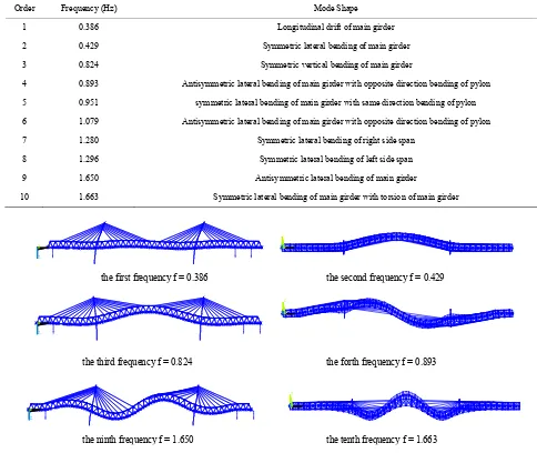
According to the dynamic analysis model of the ca- ble-stayed bridge established, the natural vibration char- acters of the bridge are analyzed. The first ten natural frequencies and respective mode shapes can are shown in Table 1. And Figure 1 shows some mode shapes.
Because of the floating-type of main girder, the first order natural mode shape is longitudinal drift, and the frequency is 0.386 Hz; the fundamental lateral modal shape is the second order modal of the bridge, its fre-quency is 0.426 Hz, and the modal shape is symmetric bending of main girder; the fundamental vertical modal shape is the third order modal of the bridge with the fre-quency is 0.842 and symmetric vertical bending of main girder; and the fundamental torsion modal shape is
Table 1. List table of first ten natural frequencies and mode shapes.
Order Frequency (Hz) Mode Shape
1 0.386 Longitudinal drift of main girder
2 0.429 Symmetric lateral bending of main girder
3 0.824 Symmetric vertical bending of main girder
4 0.893 Antisymmetric lateral bending of main girder with opposite direction bending of pylon
5 0.951 symmetric lateral bending of main girder with same direction bending of pylon
6 1.079 Antisymmetric lateral bending of main girder with opposite direction bending of pylon
7 1.280 Symmetric lateral bending of right side span
8 1.296 Symmetric lateral bending of left side span
9 1.650 Antisymmetric lateral bending of main girder
10 1.663 Symmetric lateral bending of main girder with torsion of main girder
X
Y Z
X
Y Z
X
Y Z
X
Y Z
X
Y Z
X
Y Z
the first frequency f = 0.386 the second frequency f = 0.429
the third frequency f = 0.824 the forth frequency f = 0.893
[image:2.595.53.537.319.727.2]the ninth frequency f = 1.650 the tenth frequency f = 1.663
the tenth order of the bridge, its frequency is 1.663 Hz with the symmetric torsion of main girder.
3. Realization of Vehicle-Bridge Coupling
Vibration in Multi-Body System
The behavior of the vehicle-bridge system is a complex coupled time-varying dynamic problem. Such a problem is generally solved by a numerical simulation based on a dynamic interaction model for the whole vehicle -bridge system. Theoretically, the analysis model for the vehicle- bridge system is composed of two subsystems, the mov-ing vehicle subsystem and the bridge subsystem, which are simulated as two elastic substructures, each of them characterized by some vibration patterns. The two sub-systems interact with each other through the contact forces between the wheels and the rail surface.
3.1. Multi-Body Dynamics Model of Vehicle
Multi-body system dynamics is adopted to establish the vehicle system 3-D model [3]. The inter-relationship be- tween each body is realized by the force element which reflects complex features and motion constraint hinge for realizing the stylized modeling, and multi-body dynamics equations are formed automatically. The defects of tra- ditional derivation method are corrected by the proposal modeling method, so it is considered to be powerful evi- dence of a breakthrough in the vehicle dynamics.
In the multi-body dynamics modeling and simulation of the vehicle system, the characteristics and connection of each body in the vehicle can be confirmed by the defi- nition of rigid body, hinge, constraint, force element, wheel-rail contact model and so on, and then a series of dynamic governing equations are formed [4], the vehicle dynamics model can be divided into three parts from the viewpoint of spring suspension system, car body, boogie and wheel-set. The German ICE Electric Multiple Unit (EMU) train calculation model is set up by multi-system dynamics software SIMPACK. Wheel-set is linked to the bogie frames through the primary suspension, and the bogie frames is linked to the car body through the sec- ondary suspension. Not only two dampers, two snakelike movement dampers and two vertical dampers, but also elastic lateral stoppers are assembled between the car body and bogie. There are 42 degree of freedom in the vehicle model with 34 single hinges and 8 constraints. And the Multi-body dynamics model of locomotive is shown in Figure 2. The composition of the train is 2 × (locomotive + trailer + 3 × locomotive + trailer + loco-motive), and the total number of cars is 16, the multi- body dynamics model of train is shown in Figure 3.
[image:3.595.309.541.87.215.2]Based on the theory of multi-body dynamic system, the equations of motion for the ith vehicle can be derived as follows:
[image:3.595.308.539.250.388.2]Figure 2. Multi-body dynamics model of locomotive.
Figure 3. Simulation model of coupled vibration.
Mv
xv
Cv
xv
Kv
xv F (1)where
Mv ,
Cv and
Kv denote the mass, dampand stiffness matrices of v hicle respectively; e
xvdenotes the column vector of general unknown
dis-
placement, v =
x xt
and
2
2
=
v
x x
t
.
F de-notes the column vector of exciting forces.
3.2. Co-Simulation of SIMPACK and ANSYS
[7]. The normal force between wheel and rail is deter- mined by Hertz nonlinear contact theory, and the vertical and horizontal creep forces is obtained aided by the equivalent Hertz contact characteristics and Kalker’s simplified nonlinear rolling contact theory-FASTSIM Algorithm [8].
4. Calculation and Analysis of
ration
[image:4.595.58.536.467.737.2]Th um ver-
Table 2. Responses of locomotive and trailer.
Speed cases [km/h] 270 290 300
Vehicle-Bridge Coupled Vib
e 3-D dynamic responses, such as the maxim
tical and lateral vibration acceleration of the vehicle, comfort index, rate of wheel load reduction, derailment coefficient, axle lateral force, vertical and horizontal dy- namic displacement of the bridge, vibration acceleration of the bridge, dynamic coefficients and so on, are calcu lated by the co-simulation of multi-body system dynam- ics and finite element method when the ICE EMU train passes the long span cable-stayed bridge at different speeds. Then the responses mentioned above are evalu- ated according to the current specification requirement. Germany low-interference spectrum is adopted as the ex- citation of track irregularity during the calculation, and vertical, horizontal, longitudinal and gauge irregularities are taken into consideration and the samples of these four kind irregularities are obtained by the trigonometric se- ries. There are four speed cases, 250, 270, 290 and 300 km per hour respectively. The responses of locomotive and trailer are shown in Table 2, and the responses of the bridge under different train operating speeds are shown
in Table 3. Comfort index is evaluated by Sperling index Wz. The reduction rate of wheel weight in the Table 2 is defined as ΔP/P, ΔP is the reduction magnitude of wheel weight at the decrease side of the wheel weight, and P is the static wheel weight.
As shown in Tables 2 and 3, generally speaking the vibration responses of the vehicle and bridge gradually increase along with the speed increase. In all 4 calcula-tion cases, the maximum of derailment coefficient is 0.211, and the maximum of reduction rate of wheel weigh is 0.262. According to the Specification GB- 559985, both of these two indexes are less than the sec-ond limit value 1.0 and 0.6 respectively. So the train run-ning safety can be guaranteed. The maximum vertical and lateral acceleration of vehicle are 1.066 m/s2 and 0.681 m/s2 respectively, both of these two indexes are
less than their corresponding limits values, 1.3 and 1.0 m/s2. Both the vertical and lateral comfort index is less
than 2.5, which means the comfort index is “excellent”. The maximum of vertical displacement in the mid-span of main span is 123.688 mm, the vertical deflection-span ratio is 1/1843 correspondingly, and the maximum of lateral displacement in the mid-span of main span is 2.749 mm, the lateral deflection-span ratio is 1/83,000 correspondingly. The maximum vertical acceleration of bridge is 0.386 m/s2 while lateral acceleration is 0.107
m/s2. The maximum of dynamic coefficient is 1.200. All
of these results show that the bridge has a good vibration performance.
250
n [m/s2] 0.547 0.591 0.646 0.681
Lateral acceleratio
Vertical 0.
La 22. 26. 31. 33.
L Locomotive
acceleration [m/s2] 720 0.840 0.996 1.066
teral force of wheel axle [kn] 831 877 166 672
Reduction rate of wheel weight 0.184 0.212 0.243 0.262
Derailment coefficient 0.146 0.170 0.196 0.211
ateral comfort index SP 2.101 2.109 2.122 2.128
Vertical comfort index SP 2.179 2.224 2.312 2.310
Lateral acceleration [m/s2] 0.436 0.432 0.438 0.441
Vertical acceleration [m/s2] 0.687 0.746 0.853 0.933
L ]
L Trailer
ateral force of wheel axle [kn 19.134 21.432 24.201 25.871
Reduction rate of wheel weight 0.191 0.219 0.247 0.261
Derailment coefficient 0.133 0.150 0.173 0.184
ateral comfort index SP 2.145 2.120 2.098 2.088
Ta ridge under di train running speeds.
290 300
ble 3. Responses of the b fferent
Speed cases [km/h] 250 270
Mid-span of left side span 13.795 13.731 13.761 13.753
Mid-span of main span 109.345 114.489 120.599 123.688 Vertical
M Maximum
displacement [mm]
Later
M
Vertical
M Maximum
acceleration
Later
M
Maximum vertical accel
Ma /x]
id-span of right side span 13.511 13.763 14.398 14.550
Mid-span of left side span 0.574 0.505 0.485 0.495
Mid-span of main span 2.422 2.519 2.653 2.749
id-span of right side span 0.520 0.544 0.541 0.595
Mid-span of left side span 0.162 0.246 0.254 0.278
Mid-span of main span 0.309 0.311 0.319 0.386
id-span of right side span 0.135 0.211 0.254 0.343
Mid-span of left side span 0.083 0.081 0.081 0.107
Mid-span of main span 0.053 0.043 0.051 0.074 [m/s2]
id-span of right side span 0.062 0.081 0.076 0.083
eration [m/s2] 0.309 0.311 0.319 0.386
Maximum lateral acceleration [m/s2] 0.083 0.081 0.081 0.107
ximum vertical deflection-span ratio [1 2085 1991 1891 1843
Maximum lateral deflection-span ratio [1/x] 94137 90512 85940 83000
Dynamic coefficient [1+μ] 1.061 1.111 1.1700 1.200
. Conclusion
tion model of the Germany ICE Elec-
has been conducted as part
Chinese Railway Ministry Science and Technology Re-
Y. Zeng, “Vibration Analy- sis of Train-Bridge System for Cable-Stayed Bridge Sche-
me of Nanjing ing-Shanghai High
Speed Railwa gineering Journal,
, 2007, pp. 38-42.
s Supplement, Vol. 37, 2003,
5
The refined simula
tric Multiple Unit (EMU) train is set up by multi-system dynamics methods. Then the dynamic analysis model of the cable-stayed bridge is established by finite element method. Finally the dynamic responses of vehicle-bridge coupled vibration are analyzed by co-simulation based on multi-body system dynamics and finite element method when the ICE EMU train passes the long span ca- ble-stayed bridge. From the co-simulation analysis, the derailment coefficient, reduction rate of wheel weight, vertical and lateral acceleration of the vehicle are met the specification requirements, and both the vertical and lat- eral comfort index are “excellent” when the ICE EMU train passes the bridge at different working conditions. The results also show that it is safe when the train mov- ing through this bridge at the design speed of 250 km per hour with enough running safety and comfort margin for the vehicle, and the bridge structure owns good dynamic performance.
6. Acknowledgements
The research reported herein
[5]
of the result of a series of research projects granted by the Chinese National Science Foundation with 51078316,
search and Development Program with 2011G026-E & 2012G013-C, and Sichuan Province Science and Tech- nology Project with 11JC0318.
REFERENCES
[1] W. H. Guo, X. R. Guo and Q.
Yangtse Bridge on Beij y [J],” China Civil En
Vol. 32, No. 3, 1999, pp. 23-26.
[2] X. Z. Li and S. Z. Qiang, “Vehicle-Bridge Dynamic Analy- sis for Long Span Highway and Railway Bi-Purpose Ca- ble-Stayed Bridge [J],” Journal of Vibration and Shock, Vol. 22, No. 1, 2003, pp. 6-26.
[3] Z. S. Chen and C. G. Wang, “Railway Vehicle Dyna- moics and Control [M],” China Railway Press, Beijing, 2004.
[4] B. R. Miu, W. H. Zhang, S. N. Xiao, et al., “Car-Body Fatigue Life Simulation Based on Multi-Body Dynamics and FEM [J],” Journal of the China Railway Society, Vol. 29, No. 4
pp. 372-384.
[6] S. G. Cui, “Refined Simulation Research of Vehicle-Bridge Coupled Vibration Based on the Multi-Body System Dy- namics and Finite Element Method [D],” Southwest Jiao-
tong University, Chengdu, 2009. ol. 11,
[7] S. G. Cui, B. Zhu and Z. T. Huang, “Comparative Analy- sis of Different Wheel/Rail Contact Models in Vehicle
and Bridge Coupled Vibration [J],” Chinese Journal of Ap- plied Mechanics, Vol. 27, No. 1, 2010, pp. 63-67. [8] J. J. Kalker, “A Fast Algorithm for the Simplified Theory