© 2019, IRJET | Impact Factor value: 7.211 | ISO 9001:2008 Certified Journal | Page 6800
ANALYSIS OF LINEAR AND NON-LINEAR VIBRATIONS BY AL
PIEZO-LAMINATED PLATES
Umesh Bharambe1, K.K.Chaudhari2
1 M.Tech (Machine design) J T Mahajan College of Engg. Faizpur Maharashtra, India. 2 Asst.Professor(Mechanical) J T Mahajan College of Engg.Faizpur, Maharashtra, India.
---***---Abstract - Active vibration control is
defined as a technique in which the vibration of a structure is reduced or controlled by applying counter force to the structure that is appropriately out of phase but equal in amplitude to the original vibration. As a result, two opposite force cancel each other and structure stops vibrating.
In this Study, linear and nonlinear vibration analyses are to be carried out on flax fiber reinforced composites with and without an
interleaved natural viscoelastic layer.
Experimental and FE analysis is to be done in a clamped-free configuration non two stacking sequences of composites, 00and 900 the procedure
consists on exciting the specimens with piezoelectric patches with known frequency Vibration control reduction can significantly improve the performance and operation of systems and machines in various industries. As technology advances, the methods of vibration control also become more involved and therefore allow for control of more complex structures. This paper focuses on vibration control of a flexible plate system having viscoelastic layer.
Key Words: Stress concentration, stress Analysis,
Complex structure. 1. INTRODUCTION
As piezoelectric technology advances, dynamic systems present more complex problems with less obvious solutions. One common application for these advanced controllers is vibration reduction. In high precision systems, vibrations can decrease accuracies and efficiencies, and cause potentially disastrous damage. The ability to control these vibrations and minimize amplitude response to disturbances is valuable to many different industries across the board. This paper focuses on vibration control of a flexible plate system.
Adaptive structures using piezoelectric materials usually employ lead zirconium titanate (PZT) ceramic sensors and actuators to detect and mechanically deform a structure. Piezo polymer films are not usually preferred because they lack the stiffness requirements to achieve high actuation authority. The addition of the PZT material allows the structure to sense and react to its environment. Conventional adaptive structures require a network of these actuators and sensors to be bonded to the surfaces or embedded within the structure. The actuators and sensors are coupled together to form a closed-loop network. This enables the sensors to detect a change in structural deformation, and then feed the actuators with a signal to produce the desired response to the external stimulus. Advanced piezo-controllers make up a broad category within the controls field. These controllers are capable of achieving control as well as being robust and adaptive to variances in system parameters. Advanced controllers can be made effective when the system is modeled accurately. With the goal of more effective controllers, the dynamic system model pays an important role in the controller design.
2. MATHEMATICAL MODELING
Mechanical vibrations span amplitudes from meters to nanometers. Their detrimental effect on systems may be of various natures:
Failure: vibration-induced structural failure may occur by excessive strain during transient events (e.g. building response to earthquake)
Comfort: where vibrations are detrimental to comfort are numerous: noise and vibration in helicopters, car suspensions, and wind induced sway of buildings.
© 2019, IRJET | Impact Factor value: 7.211 | ISO 9001:2008 Certified Journal | Page 6801 isolation. Stiffening consists of shifting the
resonance frequency of the structure beyond the frequency band of excitation. Damping consists of reducing the resonance peaks by dissipating the vibration energy. Isolation consists of preventing the propagation of disturbances to sensitive parts of the systems. The objective of active damping is to reduce the effect of the resonant peaks on the response of the structure. From
Consider a rectangular sandwich or laminated composite plates the plane dimensions of the plate are denoted by a, b whereas the thickness of its top face sheet, core, and bottom face sheet are denoted by h1, h2, and h3, respectively. The plane
displacement components are assumed to be as the results of superposition of local and global displacement fields
Where uG, vG, and wG denote the global
components of the displacement field
While
u
L andv
L are of the two-term localdisplacement components.
Components are assumed to be linear and the local components are considered to be piecewise linear. Imposing the continuity conditions of the displacement components at the interfaces between the layers.
Figure2.1 Geometry and Coordinate System of the Plate
Therefore, independent displacement parameters left to be determined based on the next stages.
2.2 The Governing Equations of the Laminated Composite or Sandwich Plate
The governing equations are derived based on the principle of minimum total potential energy
Where U and V are the strain energy and work of the externally applied loads, respectively
Where q is the transversely distributed load and the strain and stress quantities may be determined based on the unknown displacement parameters through the following relations for the ith layer.
3. EXPERIMENTAL SETUP
The first step of the experimental system is to manufacture the Glass Fiber Plate, the Glass Fiber plates are manufactured by Hand Layup technique. The araldite is used as the Viscoelastic material to fill the core.
© 2019, IRJET | Impact Factor value: 7.211 | ISO 9001:2008 Certified Journal | Page 6802 components of the experimental systems, the type
of actuation signal employed, and post processing of the actively monitored signal, development of the new damage signature, and test results Teflon slice having dimensions (50 x 50) mm are embedded in composite plate at the time of manufacturing the specimens this embedded Teflon sheet considered as a type of delamination or damage in composite plate.
Figure 3.1: Schematic Diagram of Experimental Setup
3.2 Procedure for Experimental setup by using FFT analyzer
Plate of required length is taken.
By the use of screw gauge the depth and width
of plate section were measured.
The connections of the FFT analyzer, laptop,
transducers, and model hammer along with the requisite power connections were made.
The accelerometer was fixed by beeswax to the
plate at one of the nodal points.
The function generator is used to excite the piezo patch connected to piezo by thin wires.
Then the voltage is provided by using the
function generator to the different piezo patches and the amplitude Vs frequency graph was obtained from graphical user interface.
The FFT analyzer and the accelerometer are
the interface to convert the time domain response to frequency domain. Hence the
frequency response spectrumH1 (response, force) was obtained.
By moving the cursor to the peaks of the FFT
graph, the cursor values and the resonant frequencies were recorded.
The above procedure is repeated for all the nodal points and all materials plates and all structures.
The values (i.e., natural frequencies and
resonant frequencies) obtained from the FRF spectrums were compared with respect to the FEM analysis.
Figure 3.2: AL Plates with piezo patch
3.3 Experimental Results: For AL Plate:
a) Frequency Plot for position 1 without Control:
© 2019, IRJET | Impact Factor value: 7.211 | ISO 9001:2008 Certified Journal | Page 6803
Frequency for Position 1
Frequency
No Without Control With Control
1 313 309
2 1012 991
3 2105 2089.01
4. FEM STRUCTURAL ANALYSIS
In the Numerical analysis we used ANSYS APDL software to derive the finite element model of the smart plate containing piezo patches. From this analysis we can determine the Frequencies of the natural vibrations without actuating & actuating the piezo patches. We also determine the maximum admissible actuation voltage and the maximum deflection the plate. Based on this model the smart plate is produced and result of the smart plate.
At the initial stage of design, the finite element model is sufficient which allows determining the location, size of an actuator and its power requirement. In the modeling and analysis of piezoelectric crystal typical finite element used was (SOLID5), which has piezoelectric capacity in three-dimensional couple field problem. Like other structural solid elements, this element has three displacement degrees of freedom per node. In addition to this degree of freedom the element has also potential degree for the analysis of the electromechanical coupling problems. Piezoelectric actuator inherently
[image:4.595.34.290.70.349.2]exhibits anisotropic and yield three-dimensional spatial vibration in their response to the piezoelectric actuation.
Figure 4.1: Line Model of Plate
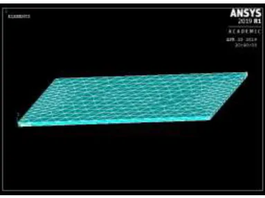
[image:4.595.338.530.156.324.2]Figure 4.2: Meshed Model
[image:4.595.356.548.365.508.2]© 2019, IRJET | Impact Factor value: 7.211 | ISO 9001:2008 Certified Journal | Page 6804
4.1ANSYS Results for Aluminium Plate:
a) Frequency plot position 1 without controller
b) Frequency plot position 1 with controller
Frequency for Position 1 Frequency
Number
Without
Control With Control
1 309.026 303.212
2 1005 987.376
3 2067 2099
5. RESULT AND DISCUSSION For Aluminum Plate:
The positions are specified in the experimental & Finite Element Setup is considered for the
Results & Discussions.The Modal Frequencies Obtained Experimentally is shown in Following Table.
Frequency for Position 1
Frequency
No Without Control Control With
% Control Obtained
1 313 309 1.2
2 1012 991 2.07
[image:5.595.38.564.55.298.2]3 2105 2089.01 0.759
Table No.5.1 Results Obtained From
Experimental Analysis for Al Plate.
Frequency for Position 1 Frequency
Number
Without Control
With Control
% Control Obtained 1 309.026 303.212 2 2 1005 987.376 1.75
3 2099 2067 1.52
Table No.5.2Results Obtained From Experimental Analysis for Al Plate
6. CONCLUSION
From the Finite Element & Experimental Results It is seen that the piezoelectric material is an effective tool for control of vibration. The size of piezoelectric patch also plays an important role to control the vibrations. Here we have used small patch but the actuations produced are good as compared.
The position of sensor is also an important factor to detect the vibrations in the plate structures. It is observed from results that the control obtained near to free end is less as compared to other locations.
It is also observed that Viscoelastic core has a great impact over the vibrations, it can be used to produce the damping effect.
The control obtained is less in composite plate, but satisfactory as compared to amplitude of vibrations.
[image:5.595.38.291.308.557.2]© 2019, IRJET | Impact Factor value: 7.211 | ISO 9001:2008 Certified Journal | Page 6805 REFERENCES
1. Dr. Kishor B. Waghulde, Dr. Bimlesh Kumar,
“Active Vibration Analysis of Piezo-Laminated Cantilever Beam”,International Journal of Scientific & Engineering Research, Volume 5, Issue 12, December-2014, ISSN 2229-5518,PP 624-628.
2. H Karagulle, L Malgaca and H F Oktem,
“Analysis of active vibration control in smart structures by ANSYS”, Institute of Physics Publishing,PII:S0964-1726(04)77278-X, (2004) 661–667.
3. Yavuz Yaman, Tarkan Caliskan, Volkan
Nalbantoglu, Eswar Prasad, David Waechter, “ACTIVE VIBRATION CONTROL OF A SMART PLATE”, ICAS2002 CONGRESS.
4. M. Kozupa, and J. Wiciak, “Active Vibration
Control of Rectangular Plate with Distributed Piezoelements Excited Acoustically and
Mechanically”, ACTA PHYSICA POLONICA,
Acoustic and Biomedical Engineering.
5. S. K. Sarangi, M. C. Ray, “Active damping of